A portable electrospinning apparatus based on a small solar cell and a hand generator: design, performance and application†
Xu
Yan‡
a,
Miao
Yu‡
ab,
Li-Hua
Zhang‡
a,
Xian-Sheng
Jia
a,
Jin-Tao
Li
a,
Xiao-Peng
Duan
a,
Chong-Chong
Qin
a,
Rui-Hua
Dong
a and
Yun-Ze
Long
*ac
aCollaborative Innovation Center for Low-Dimensional Nanomaterials & Optoelectronic Devices, College of Physics, Qingdao University, Qingdao 266071, China. E-mail: yunze.long@163.com
bDepartment of Mechanical Engineering, Columbia University, New York 10027, USA
cCollaborative Innovation Center for Marine Biomass Fibers, Materials and Textiles of Shandong Province, Qingdao University, Qingdao 266071, China
First published on 23rd November 2015
Abstract
Electrospinning (e-spinning) devices and electrospun (e-spun) ultrathin fibers have shown promising applications in various fields. However, the poor portability of conventional e-spinning devices limits some potential applications especially in the case without a plug (electricity supply). Consequently, great efforts have been made to modify e-spinning setups with good portability. In this article, a solar cell and a hand generator-powered portable e-spinning (SHPE) setup with good flexibility is introduced, which can be used outdoors without a plug. The SHPE device shows good spinning efficacy both in solution and melt e-spinning processes for a wide range of polymers. Moreover, the designed SHPE apparatus demonstrates potential application in wound dressing by in situ e-spinning fibers onto human skin directly.
1 Introduction
Currently, electrospinning (e-spinning) has attracted much attention as an effective, economical, and a highly versatile method to process solutions or melts into continuous ultrathin fibers with diameters ranging from a few micrometers to several nanometers.1–5 Up to now, e-spinning has been applied to fabricate hundreds of kinds of polymer nanofibers including synthetic and natural polymers,6 as well as metals7 and ceramics.8 These electrospun (e-spun) nanofibres have shown great potential applications in filtration,9 solar cells,10 photoelectric devices,8 sensors,11,12 tissue engineering,6,13 wound dressing14,15 and drug-delivery.15,16Apart from the special e-spun nanofibers, great efforts have been made to modify the e-spinning devices to achieve potential applications in the medical field.17–23 For example, Edirisinghe et al. designed a portable handheld electrohydrodynamic (EHD) device which could provide both e-spinning and electrospraying (e-spraying) processes, and can be applied in generating wound dressings or tissue scaffolds in situ.17,18 Similarly, we have reported a portable airflow-directed in situ e-spinning device which can precisely control the deposition of ultrathin polymeric fibers onto wound sites, and realize rapid hemostasis.19 However, these two portable in situ e-spinning apparatuses show portability limited to their handheld spinnerets, while whole devices are still heavy and their power supplies still rely on city electric supply which confine the workplace of these devices where a plug must connect with a power grid.
Recently, a series of battery-operated portable e-spinning devices were reported to enhance their transportability and flexibility.20–22 A battery-operated portable e-spinning setup which enables control over the voltage and the flow rate of the polymer solution has been proposed.21 It is shown to be able to produce both submicron fibers and particles made of several polymers and in situ applied to wound healing. We also reported a battery-operated handheld portable e-spinning apparatus with a very small volume (10.5 × 5 × 3 cm3) and quite light weight (about 120 g) to promote the e-spinning technique for potential day-to-day applications.22 These battery-operated e-spinning apparatuses have good portability, but the battery life is limited. Moreover, these devices are designed only for solution e-spinning, and not for melt e-spinning. Additionally, we have developed a self-powered e-spinning apparatus based on a hand-operated Wimshurst generator, which makes the e-spinning work without electric supply or battery.23,24 However, the high voltage provided by the Wimshurst generator may not be very stable.
In this study, a solar cell and a hand generator-powered portable e-spinning (SHPE) apparatus is introduced, which can be used both for solution and melt e-spinning of several kinds of functional polymers outdoors without a plug. The detailed design and performance of the SHPE apparatus are studied. Moreover, the potential application of this device in in situ wound dressing is also discussed.
2 Apparatus and experiments
2.1 Design of the e-spinning apparatus
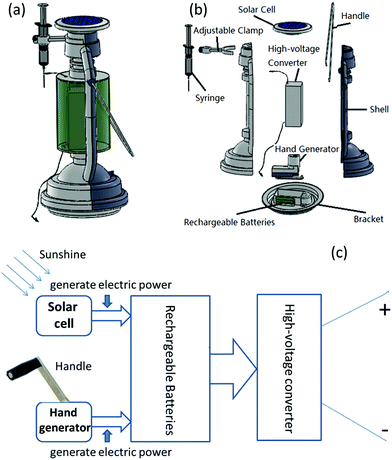
It is known that a typical e-spinning apparatus consists of three major components: a high voltage power supply, an electrically conductive spinneret, and a collector separated at a defined distance.2–4 Accordingly, the designed SHPE device can be treated as a contractible typical e-spinning device as shown in Fig. 1. In particular, the power supply system of the SHPE apparatus includes a solar cell (5 V/140 mA), a hand generator (5 V/200 mA), a set of rechargeable batteries (NiMH AA) and a high-voltage converter (FBY-4.8 V) as displayed in the middle of Fig. 1b, which can minimize the volume and weight, improve the portability of the device consequently, and ensure that the SHPE device can work anywhere. The process diagram (Fig. 1c) exhibits the operating principle of the power supply system. During spare time, this device can be placed under sunshine to generate electricity by the solar cell, or by turning the handle of the generator to recharge batteries. The principle of the hand generator is electromagnetic induction, spinning a coil of wire around a magnet. Moreover, the generated electricity can be stored in a set of rechargeable batteries (3.6 V, 3900 mA h) and then translated into a high voltage (∼3.8 kV) through a high-voltage converter, which is high enough to ensure solution or melt e-spinning at a fixed distance. In addition, in order to achieve a higher and tunable voltage (e.g., 0–14 kV (ref. 21)), one can use a much more powerful high-voltage converter (e.g., F101, EMCO High Voltage Corporation).2.2 Preparation of materials for solution and melt e-spinning
For solution e-spinning, polyvinylpyrrolidone (PVP, 250 kDa, ACROS) was dissolved in anhydrous ethanol (Sinopharm Chemical Reagent Co., Ltd, China) at 13 wt%. Poly(e-caprolactone) (PCL, 100 kDa, ACROS) was dissolved in acetone (Sinopharm Chemical Reagent Co., Ltd, China) at 18 wt%. Polystyrene, (PS, 250 kDa, ACROS) was dissolved in tetrahydrofuran (THF, Sinopharm Chemical Reagent Co., Ltd, China) at 18 wt%. Poly(lactic-co-glycolic acid) (PLGA 75![[thin space (1/6-em)]](https://www.rsc.org/images/entities/char_2009.gif) :
:![[thin space (1/6-em)]](https://www.rsc.org/images/entities/char_2009.gif) 25, 150 kDa, Jinan Daigang Biomaterial Co., Ltd, China) was added into trichloromethane (TCM, Sinopharm Chemical Reagent Co., Ltd, China) at 15 wt%. Poly(vinylidene fluoride) (PVDF, 27.5 kDa, ACROS) was dissolved at 22 wt% in N,N-dimethylformamide (DMF)/ethanol (1
25, 150 kDa, Jinan Daigang Biomaterial Co., Ltd, China) was added into trichloromethane (TCM, Sinopharm Chemical Reagent Co., Ltd, China) at 15 wt%. Poly(vinylidene fluoride) (PVDF, 27.5 kDa, ACROS) was dissolved at 22 wt% in N,N-dimethylformamide (DMF)/ethanol (1![[thin space (1/6-em)]](https://www.rsc.org/images/entities/char_2009.gif) :
:![[thin space (1/6-em)]](https://www.rsc.org/images/entities/char_2009.gif) 1 v/v). Poly(lactic acid) (PLA, Mw 200 kDa, ACROS) was dissolved at 8 wt% in TCM. All solutions were agitated at room temperature under constant stirring for at least 24 h before e-spinning. For melt e-spinning, PCL, PLA and PLGA particles were prepared, and heated to their melt point before e-spinning.
1 v/v). Poly(lactic acid) (PLA, Mw 200 kDa, ACROS) was dissolved at 8 wt% in TCM. All solutions were agitated at room temperature under constant stirring for at least 24 h before e-spinning. For melt e-spinning, PCL, PLA and PLGA particles were prepared, and heated to their melt point before e-spinning.
2.3 Characterization
The morphology and the diameter of the solution and melt e-spun fibers were characterized by a scanning electron microscope (SEM, TM-1000, Hitachi), an optical microscope (BX-51, Olympus) and a zoom-stereo microscope (SMZ-168, Motic). In addition, the spinning process was recorded by a digital video camera (EX-ZR400, Canon).3 Results and discussion
3.1 Performance of the SHPE device for solution e-spinning
The solution e-spinning process of the designed SHPE apparatus has been displayed in Fig. 2, and vivid details can be found in ESI 1.† Similar to the benchtop device, the SHPE apparatus also provides a fixed position for the solutions (the tunable cramp in Fig. 1a). Once the switch is turned on, the e-spinning process can proceed smoothly. As seen in Fig. 3, the designed SHPE apparatus is able to e-spin fibers of various polymers including PCL, PLA, PS, PLGA, PVDF and PVP. The e-spinning parameters and e-spun fiber diameters are summarized in Table 1. It is found that the average diameters of the solution e-spun fibers range from 379 nm to 2266 nm, depending on the polymer solutions and e-spinning parameters, which are consistent with the performance of conventional solution e-spinning setup and guarantees the designed SHPE device as a useful e-spinning apparatus.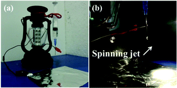 | ||
| Fig. 2 The designed SHPE device for solution e-spinning (a) and the e-spinning process of this device (b), where the solution jets are shown clearly. | ||
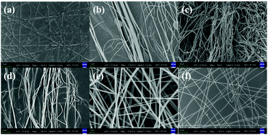 | ||
| Fig. 3 SEM images of the as-spun polymer fibers: (a) PCL, (b) PLA, (c) PS, (d) PLGA, (e) PVDF, and (f) PVP, which were produced by the SHPE device for solution e-spinning. | ||
| Polym. | Solvent | Concn. (wt%) | Volt. (kV) | Dist. (cm) | Fiber diam. (nm) |
|---|---|---|---|---|---|
| PCL | Acetone | 18 | 3.8 | 4 | 1130 ± 295 |
| PLA | TCM | 8 | 3.8 | 4 | 845 ± 188 |
| PS | THF | 18 | 3.8 | 5 | 2266 ± 517 |
| PLGA | TCM | 15 | 3.8 | 4 | 437 ± 100 |
| PVDF | DMF/ET. (1![[thin space (1/6-em)]](https://www.rsc.org/images/entities/char_2009.gif) : :![[thin space (1/6-em)]](https://www.rsc.org/images/entities/char_2009.gif) 1 v/v) 1 v/v) |
22 | 3.8 | 3 | 2153 ± 172 |
| PVP | Ethanol | 13 | 3.8 | 5 | 379 ± 120 |
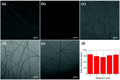
For further study, the influence of the e-spinning distance on the morphology of the fibers with the SHPE device is also investigated. For PLA solution, the e-spinning distances are set as 2, 3, 4, 5 and 6 cm. Since the provided high voltage of the SHPE is about 3.8 kV, the voltage to distance ratio is reduced as the distance increased, suggesting the reduction of strength of the electric field from 1.9 kV cm−1 to 0.63 kV cm−1. The optical images of the e-spun PLA fibers are shown in Fig. 4a–e, respectively. As seen in the images, the solution fibers are smooth and uniform. In addition, the average diameters of the as-spun PLA fibers versus the distance are displayed in Fig. 4f. It is found that with an increase of spinning distance from 2 to 4 cm, the PLA fiber diameter decreases significantly, owing to the increase of bending and stretching time of charged jets. However, on further increasing the spinning distance from 4 cm to 6 cm, the PLA fiber diameter increases due to weakened electric field strength and thus the electrostatic stretching force. The minimum fiber diameter is obtained under the electric field strength of 0.95 kV cm−1, which agrees with the former study that a general electric field intensity of 1.0 kV cm−1 resulted in solution e-spun nanofibers with the lowest average diameters.15
3.2 Performance of the SHPE device for melt e-spinning
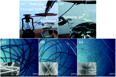
Besides solution e-spinning, the SHPE apparatus can also be used for melt e-spinning by changing the spinneret and syringe into a conical metal nozzle, in which the polymer particles can be heated into a melt by a heat gun, as shown in Fig. 5a. Once the polymer balls became a melt, the melt e-spinning process started and the melt jet rushed into the collector, cooled and solidified into microfibers, as shown in Fig. 5b. The vivid details of melt e-spinning with the SHPE device are shown in ESI 2,† which demonstrates the ability of SHPE to melt e-spinning. Moreover, different materials including PCL, PLA and PLGA can be melt e-spun into microfibers with the SHPE device, as displayed in Fig. 5c–e. The melt e-spinning parameters and average diameters of e-spun fibers are summarized in Table 2. The average diameters of the e-spun polymer fibers varied from 41.99 μm to 13.89 μm, and the fibers were smooth and uniform, indicating that the SPHE device can be used as a beneficial melt e-spinning setup.| Poly. | Temp. (°C) | Volt. (kV) | Dist. (cm) | Fiber diam. (μm) |
|---|---|---|---|---|
| PCL | 140 | 3.8 | 4 | 41.99 ± 3.96 |
| PLA | 160 | 3.8 | 4 | 17.76 ± 3.20 |
| PLGA | 120 | 3.8 | 4 | 13.89 ± 2.06 |
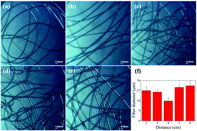
In Fig. 6a–e, we show the smooth and uniform melt e-spun PLA fibers under the e-spinning distances at 2, 3, 4, 5 and 6 cm, respectively. It is found that the melt-spun PLA fibers show a similar relationship of the fiber diameter versus the spinning distance with the solution e-spinning, namely, the thinnest fibers were produced at a middle spinning distance of 4 cm, as shown in Fig. 6f. The decrease of the as-spun fiber diameter with the increase of spinning distance from 2 to 4 cm could be ascribed to a longer stretching time for the melt jet bending and thinning.24 However, the increase of PLA fiber diameter with a further increase of spinning distance from 4 to 6 cm may be owing to the reduction of the electric field strength and thus the electrostatic drawing force.25,26 Both the solution and melt e-spinning processes based on the designed SHPE apparatus suggest that the optimized e-spinning distance for the SHPE apparatus is about 4 cm, which can well match the need of laboratory use and in situ application in wound dressing. Moreover, the effective spinning distance can be increased by changing a more powerful high-voltage converter.21
3.3 Potential application of the SHPE apparatus
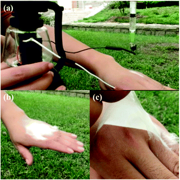
As mentioned above, the SHPE device can process both solution and melt e-spinning smoothly, and several polymers can be e-spun into submicron fibers. The e-spun fibers show high surface area to volume ratio and high porosity, which is beneficial for wound healing.1,5,6,14,15 Consequently, the SHPE apparatus also has potential applications on wound dressing similar to the previously reported portable apparatuses.17,21–24 As shown in Fig. 7, the SHPE device can e-spin PLGA fibers onto human skin conveniently even outdoors. As can be found in Fig. 7b, the PLGA fibrous membrane can be in situ e-spun onto the hand, and forms a thin film on the surface of the skin like a second layer of skin due to electrostatic attraction forces. The e-spun PLGA fibrous membrane shows good flexibility and compactness, and can be easily removed if needed [see Fig. 7c]. The more vivid details of the SHPE used as a wound dressing device can be found in ESI 3,† which demonstrates that the SHPE device is suitable for wound healing outdoors both for its ability to process in situ e-spinning and for its portable power supply system based on both a solar cell and a hand generator.4 Conclusions
In conclusion, in order to improve the portability and spinning efficacy of an e-spinning device, a solar cell and a hand generator-powered portable e-spinning apparatus has been proposed. The power supply system based on a solar cell and a hand generator ensures that the SHPE device can work in various places, not only in laboratory but also outdoors. Additionally, the SHPE device is shown to be able to process both solution and melt e-spinning for different kinds of polymers. Moreover, the SHPE apparatus can be performed as a wound dressing strategy by in situ e-spinning fibers onto human skin directly even outdoors, which demonstrates great benefits of a portable e-spinning device compared to a conventional e-spinning setup.Acknowledgements
This work was supported by the National Natural Science Foundation of China (51373082), the Taishan Scholars Program of Shandong Province, China (ts20120528), and the Postdoctoral Scientific Research Foundation of Qingdao.Notes and references
- Z. M. Huang, Y. Z. Zhang, M. Kotaki and S. Ramakrishna, Compos. Sci. Technol., 2003, 63(15), 2223–2253 CrossRef CAS.
- W. E. Teo and S. Ramakrishna, Nanotechnology, 2006, 17(14), R89 CrossRef CAS PubMed.
- S. Park, K. Park, H. Yoon, J. Son, T. Min and G. Kim, Polym. Int., 2007, 56(11), 1361–1366 CrossRef CAS.
- A. Greiner and J. H. Wendorff, Angew. Chem., Int. Ed., 2007, 46(30), 5670–5703 CrossRef CAS PubMed.
- N. Bhardwaj and S. C. Kundu, Biotechnol. Adv., 2010, 28(3), 325–347 CrossRef CAS PubMed.
- R. Sridhar, R. Lakshminarayanan, K. Madhaiyan, V. A. Barathi, K. H. C. Lim and S. Ramakrishna, Chem. Soc. Rev., 2015, 44, 790–814 RSC.
- H. Wu, L. Hu, M. W. Rowell, D. Kong, J. J. Cha, J. R. McDonough, J. Zhu, Y. Yang, M. D. McGehee and Y. Cui, Nano Lett., 2010, 10(10), 4242–4248 CrossRef CAS PubMed.
- S. Chen, M. Yu, W. P. Han, X. Yan, Y. C. Liu, J. C. Zhang, H. D. Zhang, G. F. Yu and Y. Z. Long, RSC Adv., 2014, 4(86), 46152–46156 RSC.
- C. Liu, P. C. Hsu, H. W. Lee, M. Ye, G. Zheng, N. Liu, W. Li and Y. Cui, Nat. Commun., 2015, 6, 6205 CrossRef CAS PubMed.
- E. Vijayakumar, A. Subramania, Z. Fei and P. J. Dyson, RSC Adv., 2015, 5(64), 52026–52032 RSC.
- B. Sun, Y. Z. Long, Z. J. Chen, S. L. Liu, H. D. Zhang, J. C. Zhang and W. P. Han, J. Mater. Chem. C, 2014, 2(7), 1209–1219 RSC.
- H. D. Zhang, C. C. Tang, Y. Z. Long, J. C. Zhang, R. Huang, J. J. Li and C. Z. Gu, Sens. Actuators, A, 2014, 219, 123–127 CrossRef CAS.
- A. Hasan, A. Memic, N. Annabi, M. Hossain, A. Paul, M. R. Dokmeci, F. Dehghani and A. Khademhosseini, Acta Biomater., 2014, 10(1), 11–25 CrossRef CAS PubMed.
- M. Abrigo, S. L. McArthur and P. Kingshott, Macromol. Biosci., 2014, 14(6), 772–792 CrossRef CAS PubMed.
- D. S. Katti, K. W. Robinson, F. K. Ko and C. T. Laurencin, J. Biomed. Mater. Res., Part B, 2004, 70(2), 286–296 CrossRef PubMed.
- X. Hu, S. Liu, G. Zhou, Y. Huang, Z. Xie and X. Jing, J. Controlled Release, 2014, 185, 12–21 CrossRef CAS PubMed.
- P. Sofokleous, E. Stride, W. Bonfield and M. Edirisinghe, Mater. Sci. Eng., C, 2013, 33, 213–223 CrossRef CAS PubMed.
- W. K. Lau, P. Sofokleous, R. Day, E. Stride and M. Edirisinghe, Bioinspired, Biomimetic Nanobiomater., 2014, 3(2), 94–105 CrossRef.
- K. Jiang, Y. Z. Long, Z. J. Chen, S. L. Liu, Y. Y. Huang, X. Jiang and Z. Q. Huang, Nanoscale, 2014, 6(14), 7792–7798 RSC.
- Y. J. Liu, R. Ramaseshan, Y. X. Dong, A. Kumar and S. Ramakrishna, WO Patent App PCT/SG2008/000, 2010, 444 Search PubMed.
- P. A. Mouthuy, L. Groszkowski and H. Ye, Biotechnol. Lett., 2015, 37(5), 1107–1116 CrossRef CAS PubMed.
- S. C. Xu, C. C. Qin, M. Yu, R. H. Dong, X. Yan, H. Zhao, W. P. Han, H. D. Zhang and Y. Z. Long, Nanoscale, 2015, 7(29), 12351–12355 RSC.
- W. P. Han, Y. Y. Huang, M. Yu, J. C. Zhang, X. Yan, G. F. Yu, H. D. Zhang, S. Y. Yan and Y. Z. Long, Nanoscale, 2015, 7(13), 5603–5606 RSC.
- C. C. Qin, X. P. Duan, L. Wang, L. H. Zhang, M. Yu, R. H. Dong, X. Yan, H. W. He and Y. Z. Long, Nanoscale, 2015, 7(40), 16611–16615 RSC.
- J. Lyons, C. Li and F. Ko, Polymer, 2004, 45(22), 7597–7603 CrossRef CAS.
- C. S. Wang, J. W. Du, C. L. Xie and W. W. Liu, China Elastomerics, 2014, 24(2), 5–9 CAS.
Footnotes |
| † Electronic supplementary information (ESI) available. See DOI: 10.1039/c5nr06858d |
| ‡ These authors contributed to this work equally. |
| This journal is © The Royal Society of Chemistry 2016 |

