Roll-to-roll printed silver nanowires for increased stability of flexible ITO-free organic solar cell modules
Gisele A.
dos Reis Benatto
,
Bérenger
Roth
,
Michael
Corazza
,
Roar R.
Søndergaard
,
Suren A.
Gevorgyan
,
Mikkel
Jørgensen
and
Frederik C.
Krebs
*
Department of Energy Conversion and Storage, Technical University of Denmark, Frederiksborgvej 399, DK-4000 Roskilde, Denmark. E-mail: frkr@dtu.dk
First published on 27th November 2015
Abstract
We report the use of roll-to-roll printed silver nanowire networks as front electrodes for fully roll-to-roll processed flexible indium-tin-oxide (ITO) free OPV modules. We prepared devices with two types of back electrodes, a simple PEDOT:PSS back electrode and a PEDOT:PSS back electrode with a printed silver grid in order to simultaneously explore the influence of the back electrode structure on the operational stability of the modules that did not include any UV-protection. We subjected the devices to stability testing under a number of protocols recommended by the international summit on OPV stability (ISOS). We explored accelerated ISOS-D-2, ISOS-D-3, ISOS-L-2, ISOS-L-3, ISOS-O-1 and ISOS-O-2 testing protocols and compared the performance to previous reports employing the same testing protocols on devices with PEDOT:PSS instead of the silver nanowires in the front electrode. We find significantly increased operational stability across all ISOS testing protocols over the course of the study and conclude that replacement of PEDOT:PSS in the front electrode with silver nanowires increase operational stability by up to 1000%. The duration of the tests were in the range of 140–360 days. The comparison of front and back electrode stability in this study shows that the modules with silver nanowire front electrodes together with a composite back electrode comprising PEDOT:PSS and a silver grid present the best operational stability.
Introduction
Organic solar cells have been subject to intense studies with the general purpose of increasing the power output and stability in order to push the technology towards commercialization. Most of the research however has been focusing on laboratory scale devices that do not truly reflect the vision of a low cost solution processable technology with high throughput. To develop an economically viable OPV technology it is necessary to tackle a number of issues, such as eliminating the use of indium-tin-oxide (ITO) and developing fast roll-to-roll (R2R) processing methods with little or no loss of material. These issues have received more focus in recent years and several reports of ITO-free organic solar cells have been published with alternative transparent electrodes. Graphene,1–3 highly conducting PEDOT:PSS,4–6 highly conducting PEDOT:PSS in combination with silver grids7–10 and silver nanowires (AgNWs)11–13 have for example been used as transparent electrode substitutes for ITO demonstrating similar or even better performance in comparison. Comparison of transparent electrodes includes a relationship between the conductivity of the electrode and the transmittance of light in the region of interest for the absorber of the solar cell. AgNW electrodes have in this context demonstrated extremely good conductivity/transmittance relationships which makes them a very interesting candidate for future use. The processability of AgNW by R2R has already been shown14 and the fact that only very little silver is used in the process could justify the use of silver in the form of nanowires in spite of the relatively low abundance of silver in nature. This would require that the electrode is proven stable – something that could be questioned because of the very large surface-to-volume ratio of the nanowires which could result in faster failure than bulk silver based electrodes due to promotion of degradation mechanisms at the surface. An excellent report published recently by Mayousse et al. studied the stability of pristine AgNW without encapsulation over a period of more than 2 years upon stress by elevated temperatures and high humidity, exposure to light, exposure to elevated concentrations of hydrogen sulphide and under electrical stress.15 The AgNWs were found to be very stable over time when left in ambient atmosphere in the dark and when exposed to high levels of humidity but showed decreasing conductivity over time when exposed to elevated temperatures due to breaking of some of the nanowires. The same effect was observed if the nanowires were covered with a thin layer of PEDOT:PSS and stored in the dark in which case some of the nanowires seemed to slowly be etched away by the acidic components of PEDOT:PSS. When exposed to light the electrodes experience an increase in conductivity due to sintering of the nanowire network. The overall conclusion was that although the AgNW electrode in itself is generally very stable, further studies aimed directly at the intended use of the AgNW electrodes are necessary – something that to our knowledge has not yet been performed for organic solar cell modules. Additionally, from the environmental point of view, a printed front electrode comprising a hybrid AgNW/ZnO layer saves 2 printing steps and a substantial amount of energy in the flexible OPV manufacturing.In this paper we describe a detailed stability study of fully R2R produced ITO-free organic solar cell modules using R2R printed AgNWs as front electrode, considering two different back electrodes (PEDOT:PSS with and without a printed Ag-grid) and investigating the influence on device stability. The modules were tested under ISOS-D-2, ISOS-D-3, ISOS-L-2, ISOS-L-3, ISOS-O-1, and ISOS-O-2 conditions and the results were compared with previously reported stability data for similarly sized modules that did not employ AgNWs. Our results demonstrate an increase in operational stability from a few days up to seasons under accelerated testing for polymer solar cell modules employing AgNWs.
Experimental procedures
Module processing
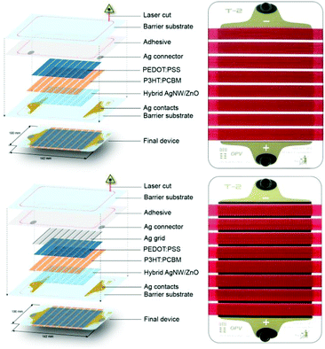
The modules were manufactured using previously described procedures.9 The front silver contacts were processed by flexo-printing on flexible barrier foil (water vapour transmission rate 4 × 10⁻² g m−2 day−1, oxygen transmission rate 1 × 10⁻² cm3(STP) m−2 day−1) without UV-filter. The previously reported 3 printing steps for the front electrode using a silver nanoparticle based Ag-grid in combination with highly conductive PEDOT:PSS and a nanoparticle ZnO layer was replaced by a rotary screen printed hybrid AgNW/ZnO electrode that was printed in a single printing step. The active layer of P3HT:PCBM was slot-die coated. Two types of modules were tested which differed only in the nature of the back electrode (Fig. 1). The modules with PEDOT:PSS/Ag-grid back electrode had the PEDOT:PSS as hole extraction layer and the Ag-grid as the back electrode, while the PEDOT:PSS back electrode modules do not have the printed Ag-grid. This means that one printing step and silver is saved in the latter case. The two device types had identical PEDOT:PSS thickness and were processed in the same manufacturing run where half of the modules were subjected to a final printing step where the silver grid/busbars were printed using rotary screen printing.Measurements
2 to 5 modules of each of the two geometries were used per ISOS test. The exact number for each test was mainly dependent on the space availability in the test setups for each test described in Table 1 and the number of available test channels. All the tests, including accurate IV-testing under calibrated light sources and outdoor measurement, were performed in the Characterization Laboratory for Organic Photovoltaics (CLOP) at the Department of Energy Conversion and Storage, DTU, Roskilde, Denmark. The outdoor experiments started on July 11th 2014 which is mid-summer in Denmark. For ISOS-D-2 the samples were kept in an oven at 65 °C; for ISOS-D-3 the samples were placed in a damp heat chamber (from Thermotron) set at 85% relative humidity (RH) and 65 °C air temperature. For ISOS-L-3 a xenon lamp based weathering chamber (from Q-Lab) was set to 65 °C air temperature, 85 °C device temperature (black panel), 50% RH and illumination of around 0.7 Sun. In ISOS-L-2 the experiment was carried out in the ambient at 65 °C under a solar simulator while in ISOS-O-1 and ISOS-O-2 the samples were left outside on a solar tracker. For both ISOS-L-2 and ISOS-O-2 the IV-curve tracing of the samples was performed using an automated acquisition setup with a Keithley 2400 SMU. In the other tests the samples were periodically removed from the ageing setup and tested under a calibrated solar simulator with AM1.5G spectrum and 1000 W m−2 of illumination. The recorded IV-curves were used to construct the degradation curves as recommended in the ISOS protocols.16 A Microsoft excel based macro was used for raw data processing and analysis.17 Images of the samples were taken using non-destructive light beam induced current (LBIC)18 mapping on a desktop system (from infinityPV ApS) and an optical microscope.| ISOS-D-2 | ISOS-D-3 | ISOS-L-2 | ISOS-L-3 | ISOS-O-1 | ISOS-O-2 | |
|---|---|---|---|---|---|---|
| Light source | None | None | Simulator AM1.5G | Simulator AM1.5G | The sun, outdoor | The sun, outdoor |
| Temperature | 65 °C (oven) | 65 °C | 65 °C | 85 °C | Ambient outdoor | Ambient outdoor |
| Relative humidity | Ambient (low) | 85% (environ. chamber) | Ambient (low) | Controlled (50%) | Ambient outdoor | Ambient outdoor |
| Characterization light source | Solar simulator | Solar simulator | Solar simulator | Solar simulator | Solar simulator | Sunlight |
Results and discussion
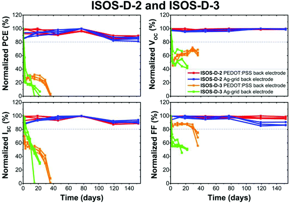
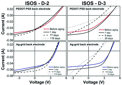
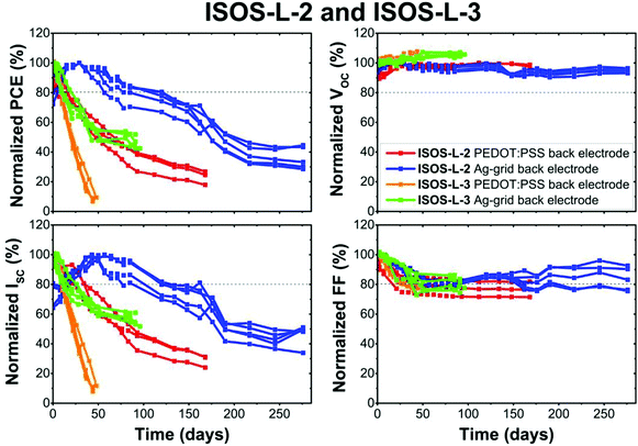
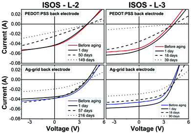
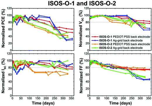
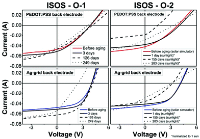
Two different types of fully R2R processed solar cell modules with AgNW front electrode were tested in this study with the difference being in the nature of the back electrode. Fig. 1 shows the device architecture as well as a photograph of the devices. P3HT:PCBM was used as the active material and either a PEDOT:PSS layer or a PEDOT:PSS layer combined with a silver grid were used for the back electrode. The active area of the modules was determined by LBIC and was found to be approximately 57 cm2 for all the tested modules. The modules were all tested according to ISOS-D-2, ISOS-D-3, ISOS-L-2, ISOS-L-3, ISOS-O-1, and ISOS-O-2 protocols. The main parameters of the different protocols are listed in Table 1. Not all the indoor tests were carried out for the same amount of time. Space issues, retrospective acknowledgement of the necessity of additional testing and device performances descending below the threshold where meaningful data could be extracted were the reasons for the differences in time span. Generally, experiments were discontinued once the devices had descended below T50 (the time it takes to reach 50% of the initial efficiency) while still presenting rapid decline in performance. Fig. 2, 4 and 9 illustrate the normalized power conversion efficiencies (PCE), open circuit voltage (VOC), short circuit current (ISC), and fill factor (FF) over time for the different tests and Fig. 3, 5 and 10 show the IV-curves of the modules before, at the beginning, halfway and close to the end of the tests.Dark tests
Fig. 2 it is obvious that in dry heat conditions (ISOS-D-2) the samples with Ag-grid back electrode show an increase in the current during the first 80 days of the test, while the samples with PEDOT:PSS exhibit rather stable performance. Nevertheless, when the humidity level is increased (ISOS-D-3), it results in a rapid degradation of all the samples after only a few days. The reason is ascribed to the diffusion of humidity through the edges of the module and the channels created at the device terminals (metal snaps), which has been demonstrated earlier for similar modules.19 In damp heat both kinds of samples experience rapid decay across all the photovoltaic parameters. The IV-curve evolution of the samples during these ageing tests is demonstrated in Fig. 3, where for the samples under ISOS-D-2 the PEDOT:PSS back electrode devices present a slight variation of current and decrease in both FF and VOC. The Ag-grid back electrode modules present an increase in performance until the 77th day and later a small decrease of current and fill factor. For the IV-curves of the ISOS-D-3 testing all samples exhibit a drastic decrease in the photovoltaic parameters. The PEDOT:PSS back electrode modules present a very slight S-shape after 9 days and for the Ag-grid back electrode it is evident indicating either de-doping of ZnO, water absorption by the PEDOT:PSS and/or further oxidation of the PEDOT:PSS/Ag interface.19Indoor light tests
The tests under illumination further confirm the deteriorating effect of the humidity when comparing the results of the ISOS-L-2 dry test and ISOS-L-3 high humidity test (Fig. 4). In the test with only light and heat (ISOS-L-2) the Ag-grid back electrode samples show an increase in performance during the first 40 days and then start to degrade. This increase also matches the results of improved conductivity of the AgNW layer under light exposure as reported by Mayousse et al.15 that demonstrated sintering of the silver nanowires at the crossing points leading to improved conductivity. Overall, the samples with Ag-grid back electrode show better stability under illumination compared to the PEDOT:PSS based samples. In the light, heat and humidity test (ISOS-L-3), the PEDOT:PSS back electrode samples show a linear decay while the Ag-grid back electrode samples stabilize at significantly lower efficiency after 40 days. The result is somewhat surprising, since such encapsulation was previously shown to result in similar rapid ageing of the samples under both ISOS-L-3 and ISOS-D-3 test conditions or even faster decay for the former.17,20 This is a possible indication that PEDOT:PSS indeed loses the conducting properties when exposed to high levels of humidity and application of the Ag-grid is believed to compensate for this failure mechanism. The almost linear decrease in the current along with the drop in the fill factor further confirms the reduction of the conductivity of the PEDOT:PSS, which has also been reported in the literature.21In relation to the IV-curves (Fig. 5), in the ISOS-L-2 tests we observe a clear decrease in ISC and FF for both types of devices. The rectifying properties of the PEDOT:PSS back electrode samples are fully lost, however they are still present in the Ag-grid back electrode samples. In the ISOS-L-3 test it is also possible to observe an increase in the first day and then the strong decrease of the fill factor and current of the samples with PEDOT:PSS back electrode. The samples with a Ag-grid back electrode also present an increase followed shortly thereafter by a decrease in ISC and FF, but they clearly retain their rectifying properties.
Bubble effect
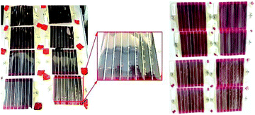
During the ageing of the samples under illumination large bubble-like defects were gradually formed in the modules with Ag-grid back electrode. In the ISOS-L-2 test, nevertheless these defects were not observed in the first 120 days of testing. The area around the bubbles became inactive resulting in partial decrease of the photocurrent as it was possible to verify with LBIC imaging (see Fig. 6). Formation of bubble-like defects was also observed during the ISOS-L-3 test, again only in the samples with Ag-grid back electrodes (Fig. 7). The effect was in this case observed after only 15 days of testing. In Fig. 8 the microscope images of the areas with and without bubbles are compared and we can observe formation of cracks in the active layer and in the AgNW/ZnO layer in the vicinity of the areas where the bubbles formed. The cracks seem to emanate from the printed Ag-busbar. The back Ag-grid is the thickest printed layer in the OPV stack and it is highly porous with the Ag solid content corresponding to just 60% of the grid volume.22 Solvents and/or gas trapped in the porosity of the printed Ag-grid could feasibly be the root cause of the bubble formation due to expansion/contraction of gasses in response to cyclic variation in temperature. However, further investigation is necessary to confirm the true nature of the effect. Even with such defects, the Ag-grid back electrode samples must be categorized as exhibiting stable behaviour until the end of the light tests although a catastrophic failure may be expected. Also, in the event that the bubble formation and subsequent delamination could be avoided, the performance over time would be much better as the decrease in short circuit current is mostly a result of active area loss due to delamination.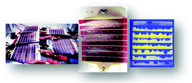 | ||
| Fig. 6 Samples with AgNW front electrode and Ag-grid back electrode under ISOS-L-2 for 240 days (left). One of these samples (centre) and its corresponding LBIC image (right). | ||
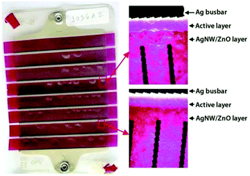 | ||
| Fig. 8 Microscope images of a sample with AgNW front electrode and Ag-grid back electrode under ISOS-L-3 of a region with (right top) and without (right bottom) a bubble defect. | ||
Outdoor tests
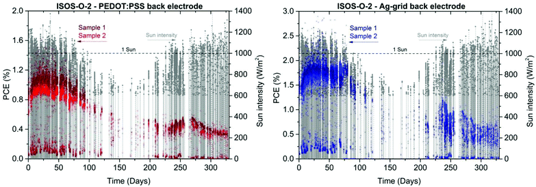
Fig. 9 shows the outdoor tests which were carried out for the entire duration of this study starting on July 11th 2014. The samples for ISOS-O-1 and ISOS-O-2 tests were placed on the same solar tracking platform. While the ISOS-O-1 samples were regularly dismounted from the platform to be measured indoors under a solar simulator and then remounted, the ISOS-O-2 samples stayed fixed on the platform connected to an automated acquisition setup. Results from these two tests are in good agreement with each other when taking all the factors that can affect the device performances into account (temperature, humidity, weather conditions, external contacts oxidation, etc.). For the ISOS-O-2 experiment the PCE and ISC data were first normalized to 1000 W m−2 since the solar cells are measured under sunlight.Most of the samples subjected to the outdoor tests start to show degradation after around 150 days of testing. For the Ag-grid back electrode samples under ISOS-O-1 the degradation seems to be evident even later after around 220 days. However these samples degrade severely after that, with a drop in both ISC and VOC, and in the end of the test they seem to stabilise at a level underperforming the PEDOT:PSS back electrode samples and the samples under the ISOS-O-2 test.
For the PEDOT:PSS back electrode modules a slight decrease in ISC, VOC and FF is observed with none of the parameters being especially dominant for ISOS-O-1 but evidently being the main cause of decrease in current for the ISOS-O-2 tests.
Fig. 10 show the PEDOT:PSS back electrode modules losing their rectifying properties, while the Ag-grid back electrode modules still preserve them as observed in the ISOS-L-3 test.
Although the fluctuating curves do not allow making clear comparison, one obvious difference among the samples stands out in the ageing curves: the fill factor ageing is surprisingly faster for the Ag-grid back electrode devices. However, when looking at the IV-curves, it is obvious that the fill factor of the PEDOT:PSS based devices is already lower from the very start and thus the comparison is somewhat biased.
The complete ISOS-O-2 measurement can be seen in Fig. 11. The four samples show an increase in PCE during the first 20 days and a decrease during the autumn and winter time, which is due to the ageing, but also gradually decreasing irradiance and temperature.
When the frequency of sunny days and irradiance intensities increase at the beginning of the spring, there is a tendency for a further increase in PCE with illumination and temperature. However PCE decreases again after a short period of low irradiance (around day 260) with the final values at around 0.4% PCE for PEDOT:PSS back electrode and 0.5% PCE for Ag-grid back electrode devices.
Taking into consideration that many degradation mechanisms are linked to humidity, the AgNW modules demonstrate considerable stability during one year of outdoor exposure. Since it is attributed to water diffusion through edges and electrodes with metal snaps, larger edges and new options for the contacts in these samples would make the devices last considerably longer.19,23
Comparison of devices with different front and back electrodes
The following paragraph compares the samples presented in this work with the previously reported stability of freeOPV modules.17 These modules have the layer stack Ag-grid/ PEDOT:PSS/ZnO/P3HT:PCBM/PEDOT:PSS/Ag-grid, therefore differing from the Ag-grid back electrode devices presented here only by the front electrode (no AgNW). The time that the device reaches 80% of its initial efficiency (T80) gives very practical information for future application and highlights where developments are needed. Typical OPV devices often experience initial rapid ageing (burn in) followed by a more stabilized phase, however in the tests performed in this work many of the stability curves show no clear stabilization phase. We therefore considered the time it takes for the device to reach 50% of its initial efficiency (T50) for better comparison. For the comparative presentation a diagram with logarithmic scale called the “o-diagram” with “o” referring to OPV is used (Fig. 12).24 The time scale is chosen to be Log4 (days) for the X-axis in order to associate the X-axis with the common time units shown in the upper part of the diagram. E0 and E50 values are represented by the Y-axis. Combined in the o-diagram are the T80 (filled markers) and T50 (open markers) values versus the initial PCE (E0) and 50% of initial PCE (E50) respectively for the devices measured in this work and for the previously reported free OPV modules (no AgNW).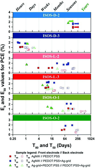 | ||
| Fig. 12 The o-diagram presents the T80 (filled markers) and T50 (open markers) values of OPV modules with (square markers) and without (triangle markers) AgNW as the front electrode under different ISOS test conditions referred in Table 1. | ||
Under ISOS-D-2 test conditions, all samples are very stable and tend to last for years. For ISOS-D-3, similarly low T80 and T50 are obtained for all the devices, since the modules have identical packaging and thus experience the same edge diffusion failure mechanisms. ISOS-L-2 presents a remarkable increase in T80 for the AgNW devices, from one day (Ag-grid front and back electrode sample) to weeks for the PEDOT:PSS back electrode devices and to months for the Ag-grid back electrode devices with the best performing devices taking seasons to reach T80. T50 also takes proportionally longer to be reached. For ISOS-L-3 a very important stability increase for the AgNW devices is also registered and even with the sensitivity of the whole device to humidity, the Ag-grid back electrode devices remain stable until the end of the test, although a catastrophic failure was expected due to the formation of bubbles previously mentioned. ISOS-O-1 show a much longer T80 from weeks for the front and back Ag-grid modules to seasons for the AgNW based devices. The modules with a PEDOT:PSS back electrode are generally less stable than the devices with Ag-grid, except in ISOS-O-1 although the variations between ISOS-O-1 and ISOS-O-2 indicate that the T80 and T50 of both AgNW based modules are in the range of variation of outdoor tests.
As mentioned before, the degradation mechanisms leading to the loss of the rectifying properties of the OPV is linked to both oxygen and water that affects the conductivity of the ZnO and PEDOT:PSS layers leading to further oxidation of the Ag-grid. The characteristic S-shape of the IV-curve indicating these mechanisms is only observed in the ISOS-D-3 test during the stability study of the AgNW based devices, possibly representing the minimization of these mechanisms with the use of the AgNW/ZnO hybrid layer as front electrode instead of a ZnO layer as well as the use of PEDOT:PSS only in the back electrode. Even though the AgNW based devices are still sensitive to humidity due to the contacts and short edge seal, the increase in T80 and T50 in the light and outdoor tests in comparison to modules with Ag-grid front and back electrodes present a substantial development in stability for large scale R2R produced OPV using AgNWs as the front electrode.
Conclusions
In the course of the stability tests and considering the overview provided by the o-diagram, we observed the following points:(a) The stability curves and T80 and T50 parameters of ISOS-L-2 test for the samples with AgNW front electrode and Ag-grid back electrode indicate that the AgNW have a positive influence on the performance and stability of devices due to the sintering of the nanowire network under light exposure which corroborates the work of Mayousse et al.;
(b) Bubble formation in the samples with Ag-grid back electrode was observed and its cause associated to solvents and/or gas trapped in the porous volume of the printed Ag-grid that expands with exposure to light and high temperature cycling.
(c) The better performance and stability of the Ag-grid back electrode samples points to the importance of the Ag-grid in conjunction with PEDOT:PSS to maintain a high back electrode conductivity in the devices;
(d) Modules with AgNWs as the front electrode demonstrate an improved stability under ISOS-L-2, ISOS-L-3 and ISOS-O-1 conditions possibly due to the use of hygroscopic PEDOT:PSS in only one of the OPV electrodes and the printing of the ZnO in a hybrid layer together with the AgNW.
The use of AgNW as the front electrode in OPV saves 2 printing steps making the manufacture of the devices faster and more environmentally friendly and such improvements in the stability of the OPV devices bring them closer to commercialization. Further improvements are expected to be achievable by increasing the edge sealing and also by employing a UV-protective filter on the front face of the modules. Finally, development of new and less porous back electrode structures that avoid the bubble formation may provide OPV devices with longer lifetimes.
Acknowledgements
The authors would like to acknowledge Dechan Angmo for help during writing of this paper. This work has been supported by the Danish Ministry of Science, Innovation and Higher Education under a Sapere Aude Top Scientist grant (no. DFF – 1335-00037A).References
- W. S. Koh, C. H. Gan, W. K. Phua, Y. A. Akimov and P. Bai, J. Sel. Top. Quantum Electron., 2014, 20, 1 CrossRef.
- Z. C. Gomez, L. De Arco, Y. Zhang, C. W. Schlenker, K. Ryu and M. E. Thompson, ACS Nano, 2010, 4, 2865 CrossRef PubMed.
- K. Kim, S. H. Bae, C. T. Toh, H. Kim, J. H. Cho, D. Whang, T. W. Lee, B. Özyilmaz and J. H. Ahn, ACS Appl. Mater. Interfaces, 2014, 6, 3299 CAS.
- Y. Zhou, F. Zhang, K. Tvingstedt, S. Barrau, F. Li, W. Tian and O. Inganäs, Appl. Phys. Lett., 2008, 92, 1 Search PubMed.
- S. I. Na, S. S. Kim, J. Jo and D. Y. Kim, Adv. Mater., 2008, 20, 4061 CrossRef CAS.
- M. Kaltenbrunner, M. S. White, E. D. Głowacki, T. Sekitani, T. Someya, N. S. Sariciftci and S. Bauer, Nat. Commun., 2012, 3, 770 CrossRef PubMed.
- D. Angmo, T. T. Larsen-Olsen, M. Jørgensen, R. R. Søndergaard and F. C. Krebs, Adv. Energy Mater., 2013, 3, 172 CrossRef CAS.
- F. C. Krebs, N. Espinosa, M. Hösel, R. R. Søndergaard and M. Jørgensen, Adv. Mater., 2014, 26, 29 CrossRef CAS PubMed.
- M. Hösel, R. R. Søndergaard, M. Jørgensen and F. C. Krebs, Energy Technol., 2013, 1, 102 CrossRef.
- J.-S. Yu, I. Kim, J.-S. Kim, J. Jo, T. T. Larsen-Olsen, R. R. Søndergaard, M. Hösel, D. Angmo, M. Jørgensen and F. C. Krebs, Nanoscale, 2012, 4, 6032 RSC.
- S. Nam, M. Song, D.-H. Kim, B. Cho, H. M. Lee, J.-D. Kwon, S.-G. Park, K.-S. Nam, Y. Jeong, S.-H. Kwon, Y. C. Park, S.-H. Jin, J.-W. Kang, S. Jo and C. S. Kim, Sci. Rep., 2014, 4, 4788 Search PubMed.
- W. Gaynor, S. Hofmann, M. G. Christoforo, C. Sachse, S. Mehra, A. Salleo, M. D. McGehee, M. C. Gather, B. Lüssem, L. Müller-Meskamp, P. Peumans and K. Leo, Adv. Mater., 2013, 25, 4006 CrossRef CAS PubMed.
- J. H. Yim, S. Y. Joe, C. Pang, K. M. Lee, H. Jeong, J. Y. Park, Y. H. Ahn, J. C. De Mello and S. Lee, ACS Nano, 2014, 8, 2857 CrossRef CAS PubMed.
- M. Hösel, D. Angmo, R. R. Søndergaard, G. A. dos Reis Benatto, J. E. Carlé, M. Jørgensen and F. C. Krebs, Adv. Sci., 2014, 1 Search PubMed.
- C. Mayousse, C. Celle, A. Fraczkiewicz and J. Simonato, Nanoscale, 2015, 2107 RSC.
- M. O. Reese, S. A. Gevorgyan, M. Jørgensen, E. Bundgaard, S. R. Kurtz, D. S. Ginley, D. C. Olson, M. T. Lloyd, P. Morvillo, E. a. Katz, A. Elschner, O. Haillant, T. R. Currier, V. Shrotriya, M. Hermenau, M. Riede, K. R. Kirov, G. Trimmel, T. Rath, O. Inganäs, F. Zhang, M. Andersson, K. Tvingstedt, M. Lira-Cantu, D. Laird, C. McGuiness, S. Gowrisanker, M. Pannone, M. Xiao, J. Hauch, R. Steim, D. M. DeLongchamp, R. Rösch, H. Hoppe, N. Espinosa, A. Urbina, G. Yaman-Uzunoglu, J.-B. Bonekamp, A. J. J. M. van Breemen, C. Girotto, E. Voroshazi and F. C. Krebs, Sol. Energy Mater. Sol. Cells, 2011, 95, 1253 CrossRef CAS.
- M. Corazza, F. C. Krebs and S. A. Gevorgyan, Sol. Energy Mater. Sol. Cells, 2014, 130, 99 CrossRef CAS.
- F. C. Krebs and M. Jørgensen, Adv. Opt. Mater., 2014, 2, 465 CrossRef CAS.
- S. A. Gevorgyan, M. V. Madsen, H. F. Dam, M. Jørgensen, C. J. Fell, K. F. Anderson, B. C. Duck, A. Mescheloff, E. a. Katz, A. Elschner, R. Roesch, H. Hoppe, M. Hermenau, M. Riede and F. C. Krebs, Sol. Energy Mater. Sol. Cells, 2013, 116, 187 CrossRef CAS.
- F. Yan, J. Noble, J. Peltola, S. Wicks and S. Balasubramanian, Sol. Energy Mater. Sol. Cells, 2012, 114, 214 CrossRef.
- J. Liu, M. Agarwal, K. Varahramyan, E. S. Berney IV and W. D. Hodo, Sensors Actuators, B, 2008, 129, 599 CrossRef CAS.
- H. F. Dam, T. R. Andersen, E. B. L. Pedersen, K. T. S. Thydén, M. Helgesen, J. E. Carlé, P. S. Jørgensen, J. Reinhardt, R. R. Søndergaard, M. Jørgensen, E. Bundgaard, F. C. Krebs and J. W. Andreasen, Adv. Energy Mater., 2015, 5, 1400736 Search PubMed.
- D. Angmo and F. C. Krebs, Energy Technol., 2015, 3, 774 CrossRef CAS.
- S. A. Gevorgyan, M. Corazza, M. V. Madsen, G. Bardizza, A. Pozza, H. Müllejans, J. C. Blakesley, G. F. a. Dibb, F. a. Castro, J. F. Trigo, C. M. Guillén, J. R. Herrero, P. Morvillo, M. G. Maglione, C. Minarini, F. Roca, S. Cros, C. Seraine, C. H. Law, P. S. Tuladhar, J. R. Durrant and F. C. Krebs, Polym. Degrad. Stab., 2014, 109, 162 CrossRef CAS.
| This journal is © The Royal Society of Chemistry 2016 |

