Cut-and-stack nanofiber paper toward fast transient energy storage
Zhen
Liu†
a,
Kun
Fu†
a,
Zhengyang
Wang†
a,
Yujie
Zhu
b,
Jiayu
Wan
a,
Yonggang
Yao
a,
Jiaiqi
Dai
a,
Myeongseob
Kim
c,
Laura
Swafford
c,
Chunsheng
Wang
b and
Liangbing
Hu
*a
aDepartment of Materials Science and Engineering, University of Maryland, College Park, MD 20742-4111, USA. E-mail: binghu@umd.edu
bDepartment of Chemical and Biomolecular Engineering, University of Maryland, College Park, MD 20742-4111, USA
cBAE Systems, Columbia, MD 21046, USA
First published on 17th February 2016
Abstract
Transient technology allows a device to disappear upon application of an external trigger. The difference between a transient energy storage device and conventional one is this ability to vanish to human eyes when needed. For the first time, a symmetric vanadium oxide (V2O5) microbattery with transient energy storage capabilities was designed and developed in this work. A V2O5 nanofiber paper, lithiated V2O5 nanofiber paper, and an electrospun polyvinylpyrrolidone (PVP) nanofiber paper were used as the positive electrode, negative electrode, and the porous membrane, respectively. All these components are electrochemically stable in the organic electrolyte battery devices, but are chemically dissoluble in alkaline, once triggered. These paper structures have small diffusion distances, resulting in good transient capability. The nanostructures also enable high-rate discharge, which is essential for transient electronic systems. Miniature battery arrays using the paper-like electrodes and separator were produced through a simple cut-and-stack process, which then can be wire-bonded to systems with radio-frequency identification (RFID) technologies.
Introduction
The past decades have witnessed both extensive and intensive developments of microelectronic devices, leading to various implementations of such devices in environmental, biological, and chemical fields.1,2 Among various emerging applications, transient electronics have developed into a unique discipline in the device community.3–8 Transient electronics can enable wide-ranging applications, especially to power up remote sensors. These sensors are tailored to function in specific natural environments and are usually expected to collect critical sets of data over a limited timescale.6 These sensors are not only required to perform well but also to vanish via a trigger such as water, light, pH, etc. within the working environment (i.e. be transient in nature).Experimental section
Preparation of polyvinylpyrrolidone (PVP) nanofiber separator
PVP (1![[thin space (1/6-em)]](https://www.rsc.org/images/entities/char_2009.gif) 300
300![[thin space (1/6-em)]](https://www.rsc.org/images/entities/char_2009.gif) 000 g per mole M.W.) was dispersed in ethanol (0.8 g per 10 mL) and stirred vigorously for 12 hours. An electrospinning process was used to convert the PVP/EtOH solution into a PVP film. The PVP separator was produced by loading the PVP/EtOH solution into a plastic syringe and extruding through a blunt needle connected to a syringe pump. The flow rate of the solution was set to 10 μL min−1. A grounded stainless steel plate was used to collect the fibers, and the distance between the needle and the fiber collector was 15 cm. A voltage of 10 kV was applied between the needle and the plate to initiate the electrospinning process. The as-collected fibers were heated in air at 60 °C for 2 hours to fully evaporate the leftover EtOH trapped in the chains of the PVP fibers.
000 g per mole M.W.) was dispersed in ethanol (0.8 g per 10 mL) and stirred vigorously for 12 hours. An electrospinning process was used to convert the PVP/EtOH solution into a PVP film. The PVP separator was produced by loading the PVP/EtOH solution into a plastic syringe and extruding through a blunt needle connected to a syringe pump. The flow rate of the solution was set to 10 μL min−1. A grounded stainless steel plate was used to collect the fibers, and the distance between the needle and the fiber collector was 15 cm. A voltage of 10 kV was applied between the needle and the plate to initiate the electrospinning process. The as-collected fibers were heated in air at 60 °C for 2 hours to fully evaporate the leftover EtOH trapped in the chains of the PVP fibers.
Green synthesis of vanadium oxide nanofibers
0.728 g of pure vanadium oxide powder (99.6%) was dissolved into 60 mL of water and vigorously stirred for 1 hour to acquire a homogeneous solution. Next, 10 mL of hydrogen peroxide (30%) was added to the solution and continuously stirred for 30 min. After 1 hour of additional stirring, a transparent orange solution was obtained. The resulting solution was then transferred into a 100 mL autoclave and heated at 210 °C for 100 hours. After the hydrothermal reaction, the yellow-orange V2O5 slurry was carefully transferred via suction filtration, washed with a copious amount of distilled water, and dried in an oven of 60 °C under ambient conditions for 24 hours to acquire a very dense vanadium fiber mat. The fiber mat was added to 200 mL of water and stirred for 3 hours to separate the nanofibers. DVPP filter paper was used for the filtration process and the final product was dried at 80 °C for 12 hours in a vacuum oven.Characterization methods
The crystal structures of the fibers were characterized using powder X-ray diffraction (XRD) on a D8 advanced with LynxEye and SolX (Bruker AXS, WI, USA). A CuKR radiation source operated at 40 kV and 40 mA. The morphology of the fibers was characterized using both a HitachiSU-70 analytical ultrahigh-resolution scanning electron microscope (SEM) and a JEOL 2100F field emission transmission electron microscope (TEM).Galvanostatic charge/discharge tests were performed on an Arbin battery test station. Cells were assembled in argon filled glove box. Electrolyte is 1.0 M LiPF6 in ethylene carbonate (EC)/diethyl carbonate (DEC) (1![[thin space (1/6-em)]](https://www.rsc.org/images/entities/char_2009.gif) :
:![[thin space (1/6-em)]](https://www.rsc.org/images/entities/char_2009.gif) 1 v/v). The mass of cathode was 0.736 mg with the dimension of 8 mm by 8 mm. The prelithiation of V2O5 was conducted at current density of 100 mA h g−1 and a voltage limit of 2.0 V. For the full cell, it was tested at a current density of 200 mA h g−1 in a voltage window of 0–1.5 V. Cyclic voltammetric (CV) curves were measured between 0 V and 1.5 V at scan rates 0.2 mV s−1. The electrochemical impedance spectroscopies (EIS) of the films were measured in the frequency range from 1 MHz to 10 mHz with the ac amplitude of 50 mV.
1 v/v). The mass of cathode was 0.736 mg with the dimension of 8 mm by 8 mm. The prelithiation of V2O5 was conducted at current density of 100 mA h g−1 and a voltage limit of 2.0 V. For the full cell, it was tested at a current density of 200 mA h g−1 in a voltage window of 0–1.5 V. Cyclic voltammetric (CV) curves were measured between 0 V and 1.5 V at scan rates 0.2 mV s−1. The electrochemical impedance spectroscopies (EIS) of the films were measured in the frequency range from 1 MHz to 10 mHz with the ac amplitude of 50 mV.
Results and discussion
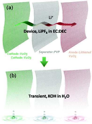
Transient electronics ubiquitously requires a transient power supply.3,9 Compared to many battery electrode materials which are already potentially transient in triggering materials (e.g. KOH solution), vanadium oxide (V2O5) is chosen for this work due to its higher capacity10,11 and faster transient behaviour in alkaline. A symmetric V2O5 microbattery towards transience energy storage was designed and developed by applying V2O5 as the positive electrode, lithiated V2O5 nanofibers with lower voltage as the negative electrode and a polyvinylpyrrolidone (PVP) nanofiber membrane as the separator to achieve transience in all of the components. All these 1D components are stable in a conventional organic electrolyte for Li-ion batteries. The 1D nanostructures not only led to fast charge–discharge in the Li-ion electrolyte, but also enabled fast (<1 min) dissolution in alkaline solutions. In this case, exposure to alkaline solution is the trigger for transience. The 1D structural network for each component enables a simple fabrication method that relies on a cut-and-stack strategy to fabricate miniature devices for future system integration.Fig. 1 shows the overall design of the transient Li-ion microbattery. The specific organic electrolyte was chosen due to its large voltage window, which enables high energy density and power density. The separator is a 15 μm-thick electrospun PVP membrane with PVP nanofiber diameters of 100 nm after pressing. The positive electrode consists of V2O5 nanofibers with a diameter of 20–50 nm and a length of 20–40 μm. The thickness of the V2O5 electrode is 30 μm. The negative electrode incorporates V2O5 nanofibers that were lithiated in an organic electrolyte. All the components are stable in the organic electrolyte, but vanish quickly in alkaline solutions. PVP is commonly referred to as a water-soluble polymer, where the dissolution of PVP nanofibers in water occurs immediately with a dissolution rate dependent on the alkalinity of the solution; meanwhile, V2O5 reacts with the alkaline solution to form a slightly yellow solution indicative of KxV2O5.9
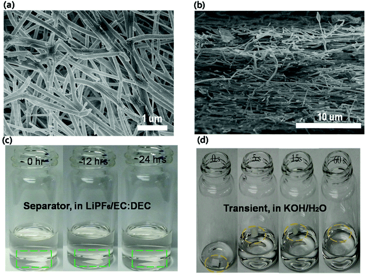
Traditional battery separators are based on microporous polyolefin membrane materials,10,11 which are normally not suitable for transient energy storage because they are limited by their dissolution in aqueous solution. The polymer PVP was chosen as the base battery separator material and fabricated using an electrospinning technique. Electrospinning yields continuous PVP (with high molecular weight) nanofibers.12–14Fig. 2a and b show the morphology of these non-woven mats. The average diameter of PVP nanofibers is approximately 200–300 nm. The nonwoven nanofiber film provides a highly porous structure that enables high electrolyte uptake and fast ionic transport.15–21 The electrolyte stability of the separator was determined by soaking the PVP film in the electrolyte for 24 hours. The PVP separator remained stable without any structural changes in organic electrolyte as shown in Fig. 2c. For the transient test, the PVP film demonstrates rapid dissolution in a KOH solution. Once the KOH solution was dropped onto the PVP, the film shrunk and completely dissolved after ∼60 seconds (Fig. 2d). The material's stability in the electrolyte and fast transience in the KOH solution demonstrates that the PVP nonwoven film can meet the requirements of transient energy storage devices.
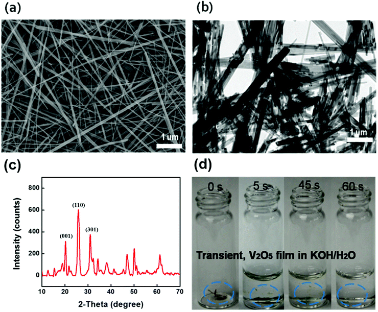
Long V2O5 nanofibers are essential for freestanding paper electrodes to achieve excellent mechanical strength and propel device miniaturization toward system integration.22–28 We designed a green chemistry process to synthesize long V2O5 nanofibers into a 3D network with enhanced mechanical properties. After revisiting the chemistry of V2O5/H2O2,29–34 we developed a two-stage approach using granular V2O5 and H2O2. Initially, there is rapid dispersion of granular V2O5 into the H2O/H2O2 mixture followed by a slow fiber formation process associated with continuous gelation. The overall green synthesis is concise, independent of any harsh chemicals or complicated surfactants, which simplifies the purification and filtration processes. Briefly, the synthesis was conducted beginning with the fast dispersion of bulk V2O5 in a mixture of hydrogen peroxide (H2O2) (30 wt%) and deionized water, without any addition of hard (metal membranes) or soft templates (polymer), and only requiring small amounts of H2O2, which is affordable for potential manufacturing scale-up. The dispersion is followed by hydrothermal treatment and a subsequent filtration process using a specific membrane filter. H2O2 serves as both a green disperser and morphological directing agent. This methodology is easily adaptable to large-scale manufacturing. Typically, V2O5 nanofibers are obtained by adding V2O5 granule powders into 50 mL DI water. A color change is observed where the slurry turns from yellow to orange, indicative of the formation of the diperoxovanadate anion [VO(O2)2(OH2)]−. Further appearance of the transparent dark red color is consistent with the monoperoxovanadate cation [VO(O2)2(OH2)3]+ and the final stage is defined as the formation of diaxovanadium cation [VO2]+. An enhanced mechanism compared to the aforementioned V2O5/H2O2 chemistry has been well established.35,36 A slow and continuous gelation takes place after the as-prepared colloidal is sealed within a teflon-autoclave, heated up to 210 °C and maintained for over 100 hours. The synthesis produces a highly viscous V2O5 nano-gel composed of random interconnected ultralong (>50 μm) nanofibers, as shown in Fig. 3a and b. The crystal structure of the ultralong V2O5 nanofibers were examined by X-ray diffraction (Fig. 3c). The XRD pattern of the sample corresponds well to the orthogonal V2O5 (space group: Pmmn(59)); (JCPDS card no. 41-1426) where the strong characteristic peaks at 20.2 degree, 26.1 degree, and 31 degree are assigned to {001} facet, {110} facet, and {301} facet; other small diffraction peaks could be indexed to the Hydrogen V2O5 (HxV2O5) (JCPDS card no. 45-0429), which were generated during the hydrothermal reaction. 2 M KOH in water was added into the container for the dissolution test. Upon the addition of the alkaline solution, the as-immersed V2O5 began to shrink and float due to rapid mass loss caused by electrolysis, and finally V2O5 was dissolved completely (Fig. 3d).
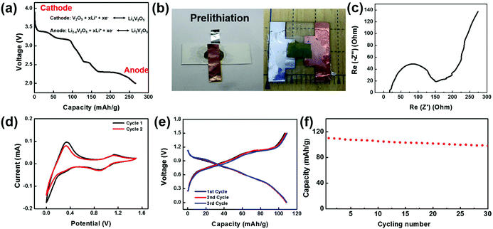
To make a full cell, V2O5 nanofiber paper serves as a cathode and lithiated V2O5 nanofiber paper as an anode (Fig. 4a). In the anode, V2O5 needs to be prelithiated for a lower potential before pairing the symmetric full cells. Prelithiation of V2O5 was conducted by building the setup as shown in Fig. 4b. A V2O5 nanofiber paper was cut into 0.8 cm by 0.8 cm squares with a mass of 0.736 mg. The cell was discharged to voltage limit of 2 V at a current density of 100 mA g−1 in argon-filled glove box. A glass slide was used as a base for the battery, with an Al foil current collector in contact with the cathode on one side and a Cu foil current collector in contact with the anode on the other side. To encapsulate the cell, polyvinyl alcohol (PVA) film was sealed by polycarbonate (PC) onto the glass slide (Fig. 4b).
Electrochemical performance of the full cell device was assembled and evaluated in an argon-filled glove box. Electrochemical Impedance analysis (EIS) of the full cell was conducted from 1 MHz to 10 mHz and the Nyquist plot is shown in Fig. 4c. The shape of the EIS spectrum consists of one semicircle in the high-frequency region and an inclined line in the low frequency region. The initial interception of the X-axis is about 25 Ohm, illustrating a small bulk resistance among the electrodes, electrolyte, and contact resistance. The X-interception of the whole semicircle corresponds to the charge transfer resistance, which is a dominant factor to the overall battery conductivity. The value of charge transfer resistance is about 96 Ohm cm2, indicating a fast electrochemical reaction and good battery performance. Cyclic voltammetric (CV) curves of the V2O5 full cell in the potential range 0–1.5 V (Fig. 4d) further illustrate the Li-ion insertion mechanism. The two redox peaks occur at 0.9 V and 0 V, while the corresponding oxidant peaks appear at a higher voltage 1.1 V and 0.3 V, which demonstrates good reversibility of the V2O5 and lithiated V2O5 system. Fig. 4e shows the voltage profile of the full cell with a potential window from 0–1.5 V cycled at 200 mA g−1. The electrode delivered a capacity of 110 mA h g−1 at the first cycle, and retained a similar capacity at the following cycles with a columbic efficiency higher than 99% indicating a superior electrochemical property. Fig. 4f shows the cycling stability of the transient battery. The battery delivered a discharge specific capacity of 98 mA h g−1 a 30th cycle, with a capacity retention of 89%. The total energy of the battery with a size of 0.8 cm by 0.8 cm is 0.0639 mWh.
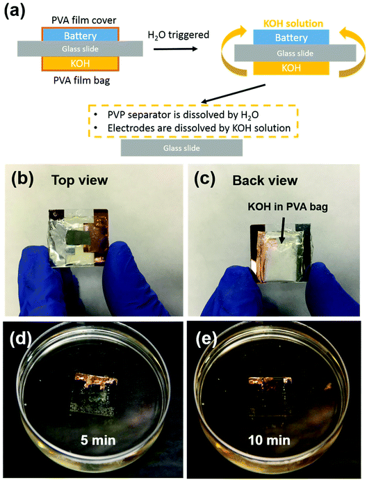
Transient energy storage devices are designed for use in transient electronic systems. We focused on the first three cycles stability, which is fatal for trigger a transient device. Very often the transient system has a limited footage for all the device components. Thus, miniaturization of the battery is critical for system integration.37–39 Here the electrode materials and separators are fibrous, which creates structured networks with excellent mechanical strength, allowing very small batteries to be fabricated. In order to demonstrate small-scale devices, we employed a simple cut-and-stack strategy. The schematic mechanism of the transient battery is shown in Fig. 5a. The battery is fabricated on a glass substrate. On the other side, a KOH-containing polyvinyl alcohol (PVA) bag is attached. Due to the hydrolysis of PVA in water, the PVA bag will be broken and KOH will be released and form KOH solution. Once the battery meets with water, the PVA film will be dissolved instantly as well as the PVP separator. In the end, the electrodes are completely dissolved in KOH solution and all of the cell achieves transience. Fig. 5b shows the front view of the full cell device. To introduce the alkaline, KOH powder was encapsulated in the PVA film, in which the edge of the bag was sealed by heating sealer. Fig. 5c shows the back of the transient full cell, with a KOH-filled bag attached onto the other side of glass slide with polycarbonate (PC) glue. This PC polymer can also be dissolved in the KOH solution. Fig. 5d and e shows the transience process of the cell in water environment. Once the transient full cell device was placed into water, the triggering mechanism as described above will apply. During this process, the highly concentrated KOH solution accelerated the dissolution of the full cell, including the V2O5 cathode, and the lithiated V2O5 anode. In the end, most of the full cell components were dissolved and the battery achieved transience. Note that among all the components, only the glass slide and the Cu foil as the current collector remained. Glass was used as the support for the demonstration; in real system integration transient batteries will be integrated in already-developed other transient system component (e.g. on Si chips that is dissolvable in KOH). The Cu foil can be replaced with an ∼50 nm Cu deposited on battery electrode before battery assembly, which disintegrates together with the battery electrode and becomes invisible to human eyes. The transient energy device are composed of soft materials, i.e., V2O5 nanofibers, PVP nanofibers and CNT. Both electrode (V2O5 nanopaper) and separator (PVP polymer thin film) can be bended multiple times without obvious damage on surface. The flexibility of battery component can be extended into the system integration, which allow the battery been sealed to various types of packages such as aluminum or polymer based sealing.
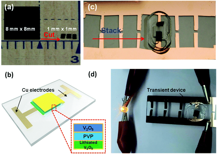
A simple cut-and-stack strategy was further employed to fabricate Li-ion microbattery arrays on glass substrates, which can be potentially integrated into a transient system using a standard process such as wire bonding. Fig. 6a depicts a V2O5 electrode (8 mm by 8 mm) cut into 64 1 mm by 1 mm pieces. A similar cutting procedure can be used for both the lithiated V2O5 electrode as well as the PVP separator. The freestanding electrodes and separator can be trimmed into any size depending on the desired device dimensions. A schematic of the V2O5/lithiated V2O5 cell is shown in Fig. 6c. A fully assembled, 1 mm by 1 mm device is shown in Fig. 6b. The V2O5 cathode, PVP separator, and Li-V2O5 anode are stacked together on a copper coated glass substrate. Since the PVP membrane exhibits high electrolyte uptake and preferable electrolyte stability, the separator was soaked in electrolyte before assembling the device unit. Note that the device array is also sealed from the top using a thin PDMS film. The 1 mm2 cell has a total energy output of over 5 mJ. Fig. 6d shows the device used to light up a 1.5 V LED bulb. Four energy devices can be incorporated onto the Cu-coated substrate in parallel (Fig. 6d). We are capable of prepare 100 pieces 1 mm by 1 mm area sized electrode chips from the 10 mm by 10 mm film, which can further assemble to 50 transient battery devices; we foresee the potential development of the automation of electrode film cutting and micro-battery assembly technique, which will enable the specific energy requirements by various batteries combination strategies.
Conclusions
In summary, we designed and fabricated the first transient Li-ion battery that operates in organic electrolyte yet dissolves rapidly in alkaline solution through a simple cut-and-stack procedure with nanofiber papers. The nanoscale fibrous structure of the separator and the electrodes leads to excellent electrochemical performance with fast transience capabilities. The structure also demonstrates excellent mechanical strength, which enabled manufacturing methods to produce miniaturized devices for future system integration. A simple cut-and-stack strategy was also demonstrated to fabricate Li-ion microbattery arrays on glass substrates, which can integrated using a standard process such as wire-bonding.Acknowledgements
We acknowledge the support of the Defense Advanced Research Projects Agency (DARPA) under Contract No. HR0011-14-C-0012.References
- M. Irimia-Vladu, Chem. Soc. Rev., 2014, 43, 6470 RSC.
- B. C. Melot and J. M. Tarascon, Acc. Chem. Res., 2013, 46, 1226 CrossRef CAS PubMed.
- C. Dagdeviren, S. W. Hwang, Y. W. Su, S. Kim, H. Y. Cheng, O. Gur, R. Haney, F. G. Omenetto, Y. G. Huang and J. A. Rogers, Small, 2013, 9, 3398 CrossRef CAS PubMed.
- X. Huang, Y. H. Liu, S. W. Hwang, S. K. Kang, D. Patnaik, J. F. Cortes and J. A. Rogers, Adv. Mater., 2014, 26, 7371 CrossRef CAS PubMed.
- S. W. Hwang, D. H. Kim, H. Tao, T. I. Kim, S. Kim, K. J. Yu, B. Panilaitis, J. W. Jeong, J. K. Song, F. G. Omenetto and J. A. Rogers, Adv. Funct. Mater., 2013, 23, 4087 CrossRef CAS.
- S. W. Hwang, H. Tao, D. H. Kim, H. Y. Cheng, J. K. Song, E. Rill, M. A. Brenckle, B. Panilaitis, S. M. Won, Y. S. Kim, Y. M. Song, K. J. Yu, A. Ameen, R. Li, Y. W. Su, M. M. Yang, D. L. Kaplan, M. R. Zakin, M. J. Slepian, Y. G. Huang, F. G. Omenetto and J. A. Rogers, Science, 2012, 337, 1640 CrossRef CAS PubMed.
- S. K. Kang, S. W. Hwang, H. Y. Cheng, S. Yu, B. H. Kim, J. H. Kim, Y. G. Huang and J. A. Rogers, Adv. Funct. Mater., 2014, 24, 4427 CrossRef CAS.
- L. Yin, H. Y. Cheng, S. M. Mao, R. Haasch, Y. H. Liu, X. Xie, S. W. Hwang, H. Jain, S. K. Kang, Y. W. Su, R. Li, Y. G. Huang and J. A. Rogers, Adv. Funct. Mater., 2014, 24, 645 CrossRef CAS.
- H. A. Mady, S. E. Negm, A. S. A. Moghny, A. S. Abd-Rabo and A. A. Bahgat, J. Sol-Gel Sci. Technol., 2012, 62, 18 CrossRef CAS.
- H. Lee, M. Yanilmaz, O. Toprakci, K. Fu and X. W. Zhang, Energy Environ. Sci., 2014, 7, 3857 CAS.
- H. Y. Guan, F. Lian, Y. Ren, Y. Wen, X. R. Pan and J. L. Sun, Int. J. Miner., Metall. Mater., 2013, 20, 598 CrossRef CAS.
- H. Khan, P. Mehta, H. Msallam, D. Armitage and Z. Ahmad, J. Drug Targeting, 2014, 22, 790 CrossRef CAS PubMed.
- X. M. Xu, J. F. Zhang and Y. W. Fan, Biomacromolecules, 2010, 11, 2283 CrossRef CAS PubMed.
- J. S. Varabhas, G. G. Chase and D. H. Reneker, Polymer, 2008, 49, 4226 CrossRef CAS.
- B. Szubzda, A. Szmaja, M. Ozimek and S. Mazurkiewicz, Appl. Phys. A: Mater. Sci. Process., 2014, 117, 1801 CrossRef CAS.
- Q. J. Wang, W. L. Song, L. N. Wang, Y. Song, Q. Shi and L. Z. Fan, Electrochim. Acta, 2014, 132, 538 CrossRef CAS.
- Y. E. Miao, G. N. Zhu, H. Q. Hou, Y. Y. Xia and T. X. Liu, J. Power Sources, 2013, 226, 82 CrossRef CAS.
- X. S. Huang and J. Hitt, J. Membr. Sci., 2013, 425, 163 CrossRef.
- X. S. Huang, J. Solid State Electrochem., 2011, 15, 649 CrossRef CAS.
- S. S. Zhang, J. Power Sources, 2007, 164, 351 CrossRef CAS.
- P. Kritzer, J. Power Sources, 2006, 161, 1335 CrossRef CAS.
- N. H. A. Tran, H. Brunig, R. Boldt and G. Heinrich, Polymer, 2014, 55, 6354 CrossRef CAS.
- W. He, Z. W. Ma, W. E. Teo, Y. X. Dong, P. A. Robless, T. C. Lim and S. Ramakrishna, J. Biomed. Mater. Res., Part A, 2009, 90, 205 CrossRef PubMed.
- L. H. Zhang, E. Z. Shi, C. Y. Ji, Z. Li, P. X. Li, Y. Y. Shang, Y. B. Li, J. Q. Wei, K. L. Wang, H. W. Zhu, D. H. Wu and A. Y. Cao, Nanoscale, 2012, 4, 4954 RSC.
- R. Hinchet, S. Lee, G. Ardila, L. Montes, M. Mouis and Z. L. Wang, Adv. Funct. Mater., 2014, 24, 971 CrossRef CAS.
- Z. Chen, Y. Yuan, H. H. Zhou, X. L. Wang, Z. H. Gan, F. S. Wang and Y. F. Lu, Adv. Mater., 2014, 26, 339 CrossRef CAS PubMed.
- D. Lee, H. Lee, Y. Ahn, Y. Jeong, D. Y. Lee and Y. Lee, Nanoscale, 2013, 5, 7750 RSC.
- J. Lee, P. Lee, H. Lee, D. Lee, S. S. Lee and S. H. Ko, Nanoscale, 2012, 4, 6408 RSC.
- Y. Y. Liu, M. Clark, Q. F. Zhang, D. M. Yu, D. W. Liu, J. Liu and G. Z. Cao, Adv. Energy Mater., 2011, 1, 194 CrossRef CAS.
- W. Chen, L. Q. Mai, Y. Y. Qi and Y. Dai, J. Phys. Chem. Solids, 2006, 67, 896 CrossRef CAS.
- E. H. Liu, X. H. Li, Z. Q. He, Z. H. Hou and L. F. Deng, Chin. J. Inorg. Chem., 2003, 19, 1113 CAS.
- C. Lei, Z. Chen, H. S. Sohn, X. L. Wang, Z. Y. Le, D. Weng, M. Q. Shen, G. Wang and Y. F. Lu, J. Mater. Chem. A, 2014, 2, 17536 CAS.
- C. Z. Yan, Z. Chen, Y. T. Peng, L. Guo and Y. F. Lu, Nanotechnology, 2012, 23, 475701 CrossRef PubMed.
- Z. Chen, V. Augustyn, J. Wen, Y. W. Zhang, M. Q. Shen, B. Dunn and Y. F. Lu, Adv. Mater., 2011, 23, 791 CrossRef CAS PubMed.
- J. X. Zhu, L. J. Cao, Y. S. Wu, Y. J. Gong, Z. Liu, H. E. Hoster, Y. H. Zhang, S. T. Zhang, S. B. Yang, Q. Y. Yan, P. M. Ajayan and R. Vajtai, Nano Lett., 2013, 13, 5408 CrossRef CAS PubMed.
- B. Saravanakumar, K. K. Purushothaman and G. Muralidharan, ACS Appl. Mater. Interfaces, 2012, 4, 4484 CAS.
- S. Y. Hong, J. Yoon, S. W. Jin, Y. Lim, S. J. Lee, G. Zi and J. S. Ha, ACS Nano, 2014, 8, 8844 CrossRef CAS PubMed.
- G. Grau, R. Kitsomboonloha, S. L. Swisher, H. K. Kang and V. Subramanian, Adv. Funct. Mater., 2014, 24, 5067 CrossRef CAS.
- P. Sullivan, S. Schumann, R. Da Campo, T. Howells, A. Duraud, M. Shipman, R. A. Hatton and T. S. Jones, Adv. Energy Mater., 2013, 3, 239 CrossRef CAS.
Footnote |
| † These authors contributed equally to this work. |
| This journal is © the Partner Organisations 2016 |


