A Co3O4@MnO2/Ni nanocomposite as a carbon- and binder-free cathode for rechargeable Li–O2 batteries†
Xiaopeng
Han
ab,
Fangyi
Cheng
a,
Chengcheng
Chen
a,
Fujun
Li
*a and
Jun
Chen
ac
aKey Laboratory of Advanced Energy Materials Chemistry (Ministry of Education), College of Chemistry, Nankai University, Tianjin 300071, China
bKey Laboratory of Advanced Ceramics and Machining Technology (Ministry of Education), School of Materials Science and Engineering, Tianjin University, Tianjin 300072, China
cCollaborative Innovation Center of Chemical Science and Engineering, Nankai University, Tianjin 300071, China. E-mail: fujunli@nankai.edu.cn
First published on 11th April 2016
Abstract
Rational design and synthesis of cathode catalysts are crucial for enhancing the performance of rechargeable Li–O2 batteries. Here, we report a controlled synthesis of the nanocomposite, Co3O4 nanohorns coated with MnO2 nanosheets on a Ni foam (Co3O4@MnO2/Ni). It integrates the catalytic activities of oxygen reduction and oxygen evolution reactions and functions as a carbon- and binder-free cathode catalyst for rechargeable Li–O2 batteries. This nanocomposite catalyst presents a small discharge/charge voltage gap of 0.76 V (a low polarization) and a long cycle life of 170 cycles at 300 mA g−1, coupled with an ionic liquid-based electrolyte, 0.5 M lithium bis(trifluoromethanesulfonyl)imide (LiTFSI) in 1-ethyl-3-methylimidazolium bis(trifluoromethanesulfonyl)imide (EMITFSI), which are much better than those based on the individual Co3O4 and MnO2 cathodes. The enhanced electrochemical performance is ascribed to the integrated bifunctional catalytic activities and the porous micro/nanostructure of the Co3O4@MnO2/Ni nanocomposite, as well as the ionic liquid-based electrolyte, indicating its promising application in rechargeable Li–O2 batteries.
Introduction
Rechargeable Li–O2 batteries, which show a high theoretical energy density of ∼11![[thin space (1/6-em)]](https://www.rsc.org/images/entities/char_2009.gif) 680 Wh kg−1 (based on the mass of Li), have attracted much attention in recent years.1–4 However, one critical issue of such batteries is to keep the high catalytic activities of cathode catalysts towards both oxygen reduction reaction (ORR) and oxygen evolution reaction (OER).5,6 Among various bifunctional catalysts,7–11 transition metal oxides with micro/nanostructures have been applied as ORR or OER electrocatalysts owing to their low cost and easy preparation.12–17 Specifically, Mn3+ and Mn4+ species were found to be more active for ORR, and Co3+ was demonstrated to be the active site for OER.18,19 However, the two separate functions have seldom been attempted in one system. Meanwhile, MnOx suffers from its intrinsic poor conductivity (e.g., 10−5–10−6 S cm−1 for MnO2).20,21 Integrating cobalt oxide with manganese oxide to construct a CoOx–MnOx composite is one of the strategies to achieve the synergistic effects towards both ORR and OER. Furthermore, CoOx can serve as a conductive network for MnOx. To the best of our knowledge, the application of a nanostructured CoOx–MnOx hybrid has rarely been explored in rechargeable Li–O2 batteries.
680 Wh kg−1 (based on the mass of Li), have attracted much attention in recent years.1–4 However, one critical issue of such batteries is to keep the high catalytic activities of cathode catalysts towards both oxygen reduction reaction (ORR) and oxygen evolution reaction (OER).5,6 Among various bifunctional catalysts,7–11 transition metal oxides with micro/nanostructures have been applied as ORR or OER electrocatalysts owing to their low cost and easy preparation.12–17 Specifically, Mn3+ and Mn4+ species were found to be more active for ORR, and Co3+ was demonstrated to be the active site for OER.18,19 However, the two separate functions have seldom been attempted in one system. Meanwhile, MnOx suffers from its intrinsic poor conductivity (e.g., 10−5–10−6 S cm−1 for MnO2).20,21 Integrating cobalt oxide with manganese oxide to construct a CoOx–MnOx composite is one of the strategies to achieve the synergistic effects towards both ORR and OER. Furthermore, CoOx can serve as a conductive network for MnOx. To the best of our knowledge, the application of a nanostructured CoOx–MnOx hybrid has rarely been explored in rechargeable Li–O2 batteries.
Conventional air cathodes consist of a catalyst supported on carbon black and a polymer binder. Unfortunately, carbon was revealed to be unstable in a highly oxidizing environment of cathodes, especially at high voltages. It can spontaneously react with the discharge product Li2O2 to form lithium carbonates, which are difficult to be decomposed, and thus induce high discharge/charge overpotentials.22–24 In addition, the polymer binders, such as poly(vinylidene fluoride) and polyethylene oxide, are vulnerable to O2− anions, which are intermediates of the ORR process.25,26 Therefore, employment of carbon- and binder-free air cathodes in place of the carbon counterparts is essential to circumvent or suppress side reactions for rechargeable Li–O2 batteries with long cycle life.
Herein, we report a controlled synthesis of the nanocomposite of Co3O4 nanohorns coated with MnO2 nanosheets on a Ni foam (Co3O4@MnO2/Ni) via a facile hydrothermal method. This nanocomposite integrates the respective ORR and OER catalytic activities, and works as a carbon- and binder-free cathode catalyst for Li–O2 batteries. In combination with an ionic liquid (IL)-based electrolyte, 0.5 M lithium bis(trifluoromethanesulfonyl)imide (LiTFSI) in 1-ethyl-3-methylimidazolium bis(trifluoromethanesulfonyl)imide (EMITFS), which has a low vapor pressure, wide electrochemical potential window and high chemical stability,27 the resultant Li–O2 batteries present a small discharge/charge voltage gap of 0.76 V and a long cycle life of 170 cycles of discharge and charge at 300 mA g−1. This suggests the feasibility of a catalyst design strategy for integrating the functionalities of the individual materials and its potential application as a cathode catalyst for Li–O2 batteries.
Experimental
Syntheses of materials
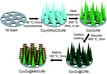
Co3O4 nanohorns on a Ni foam (Co3O4/Ni) were fabricated by a hydrothermal method. Typically, 1.45 g of Co(NO3)2·6H2O was dissolved in 50 mL of deionized water to form a homogeneous pink solution, and then 0.37 g of NH4F and 1.5 g of urea were added under constant stirring. One piece of Ni foam (3.0 × 3.0 cm in a square shape) was washed with 0.1 M HCl solution to remove the possible skin oxide and later with deionized water several times. Subsequently, the treated Ni foam and the above aqueous solution were transferred into an 80 mL Teflon-lined stainless autoclave, which was maintained at 90 °C for 5, 8, 10, and 12 h, and 120 °C for 10 h, respectively. The product-loaded Ni foam was taken out, washed, dried, and then annealed at 250 °C in air for 4 h to obtain crystallized Co3O4.The nanocomposite of Co3O4 nanohorns coated with MnO2 nanosheets on a Ni foam (Co3O4@MnO2/Ni) was prepared by the growth of MnO2 nanosheets on Co3O4 nanohorns via a carbon assisted reaction route. The synthetic procedures are schematically described in Scheme 1. The Co2(OH)2CO3 precursor was firstly obtained by a hydrothermal process at 90 °C, and its further annealing at 250 °C for 4 h resulted in the formation of porous Co3O4 nanohorns on a Ni foam. The as-synthesized Co3O4/Ni was immersed into a 0.3 M aqueous glucose solution for 24 h. After carbonization of the coated glucose in an Ar atmosphere at 450 °C for 2 h, a thin carbon layer was produced on Co3O4 nanohorns in Co3O4/Ni. Then, the carbon coated Co3O4/Ni was transferred into an 80 mL Teflon-lined stainless autoclave containing 50 mL of 0.04 M KMnO4 solution, which was heated to 120 °C and kept for 3 h. Thus, the thin carbon layer as a sacrificial template reacted with KMnO4 to generate MnO2 nanosheets on Co3O4 nanohorns. Finally, the nanocomposite of Co3O4@MnO2/Ni was obtained by washing with distilled water and ethanol three times and dried at 60 °C in a vacuum oven. With similar procedures, the bare MnO2 nanosheets on Ni foam (MnO2/Ni) were prepared by coating glucose onto the Ni foam, carbonization, and then hydrothermal treatment in the presence of KMnO4 at 120 °C. Simultaneously, Co3O4 nanomaterials were synthesized with similar procedures to those supported on a Ni foam. MnO2 nanomaterials were obtained via a hydrothermal treatment of 20 mg carbon black (Vulcan XC-72) and 50 ml of 0.04 M KMnO4 at 120 °C for 3 h after ultrasonic dispersion.
Material characterization
Micro/nanostructures and morphologies of the as-synthesized materials and the discharged/charged cathodes were characterized by powder X-ray diffraction (XRD) using a Rigaku/MiniFlex600 diffractometer with Cu Kα radiation, scanning electron microscopy (SEM) on JEOL JSM 7500F, and transmission electron microscopy (TEM) on a Philips Tecnai F20 (200 kV) equipped with an energy dispersive spectroscope (EDS). A Raman spectroscope from Thermo-Fisher Scientific was applied at 532 nm excitation (DXR) to identify the discharge/charge products during the cycles.Battery assembly
Electrocatalytic activity of the as-synthesized materials was evaluated in non-aqueous Li–O2 batteries based on CR2032 coin cells. The battery assembly was carried out in an Ar-filled glove box (Mikrouna Universal 2440/750, H2O < 0.1 ppm and O2 < 0.1 ppm). The cell consisted of a newly polished lithium foil anode (Φ14 × H0.3 mm), a prepared air cathode (Φ10 mm), a glassy fibre filter separator (Φ16 × H0.3 mm) soaked in the electrolyte 0.5 M lithium bis(trifluoromethylsulfonyl)imide (LiTFSI) in 1-ethyl-3-methylimidazolium bis(trifluoromethanesulfonyl)imide (EMITFSI) or tetraethyleneglycoldimethyl ether (TEGDME). The mechanically mixed cathode of Co3O4/MnO2/C was prepared by casting a mixture of 25 wt% Co3O4, 25 wt% MnO2, 45 wt% Vulcan carbon-72 and 5 wt% poly(vinylidene fluoride) (PVdF) onto a nickel foam and then dried at 110 °C overnight in a vacuum oven. The assembled battery was then transferred into a sealed container, which was later flushed with 1 atm high-purity oxygen.Electrochemical tests
The galvanostatic discharging and charging were carried out in a 1 atm O2 atmosphere at room temperature using a LAND-CT2001A battery-testing system after at least 5 h rest. The discharge/charge cycles of Li–O2 batteries were successively conducted without interruptions. All the current densities and specific capacities were calculated based on the weight of the loaded oxide catalysts. The mass loading of active materials in each cathode is around 0.8 mg cm−2.Results and discussion
Fig. 1 shows the XRD patterns and Raman spectra of the as-synthesized Co3O4/Ni and Co3O4@MnO2/Ni nanocomposites. The diffraction peaks of bare Co3O4 can be well indexed to its cubic spinel phase apart from the three strong diffraction peaks of the Ni substrate in Fig. 1a, according to the JCPDS card no. 42-1467. The enlarged XRD profiles in Fig. 1b indicate the formation of the birnessite-type MnO2 phase (JCPDS card no. 42-1317) in the Co3O4@MnO2/Ni nanocomposite. The relatively weak diffraction peaks of MnO2 may be ascribed to its poor crystallinity and nanosize. The structural features of the nanocomposite were further confirmed by Raman spectroscopy as shown in Fig. 1c. The vibration bands located at around 191, 480, 525 and 682 cm−1 are assigned to the F2g3, Eg, F2g1 and A1g modes of Co3O4,20 respectively. The other two Raman bands as indicated at 575 and 645 cm−1 are in accordance with the Mn–O stretching vibration and the symmetric stretching vibration of the MnO6 groups in the birnessite-type MnO2, respectively.28–30 These results indicate the formation of the Co3O4@MnO2/Ni nanocomposite.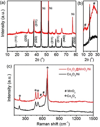 | ||
| Fig. 1 XRD patterns (a, b) and Raman spectra (c) of the as-synthesized Co3O4/Ni and Co3O4@MnO2/Ni nanocomposites. | ||
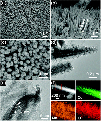
The Co3O4 nanohorns on a Ni foam (Co3O4/Ni) and the precursor of Co3O4@MnO2/Ni as shown in Scheme 1 are presented in the SEM image in Fig. 2a. It can be seen that the large-scale, dense and uniform Co3O4 nanohorns are vertically grown on the skeleton of the Ni foam. These nanohorns are several micrometers in length, as displayed in Fig. 2a and Fig. S1 (ESI†) under various magnifications. The micro/nanostructure and morphology of the Co3O4 nanohorns are dependent on the initial hydrothermal conditions, as revealed in Fig. S2, ESI.† The optimal temperature and duration are determined to be 90 °C and 10 h. The cross sectional image of the Co3O4/Ni nanocomposite in Fig. 2b displays the Co3O4 nanohorns of 1.5 μm in length and 100 nm in diameter. It is noted that the Co3O4 nanohorn is composed of numerous nanoparticles, which are connected to each other to form a highly porous structure, as depicted in the TEM image in Fig. S1, ESI.† The lattice spacing of 0.28 nm in the high-resolution TEM (HRTEM) image in Fig. S1 (ESI†) is in accordance with the (220) facet of Co3O4 in the XRD patterns in Fig. 1a. These suggest that the dense Co3O4 nanohorns are in situ formed on the Ni foam in the Co3O4/Ni nanocomposite via hydrothermal treatment.
With the formation of thin layers of MnO2 nanosheets on the Co3O4 nanohorns in Co3O4/Ni via the reaction of carbon and KMnO4, the Co3O4@MnO2/Ni nanocomposite is obtained, as depicted in Scheme 1. The top view of the Co3O4@MnO2/Ni nanocomposite is shown in Fig. 2c. The diameter of Co3O4@MnO2 increases and its surface becomes porous after coating with MnO2. The TEM observation in Fig. 2d shows that the MnO2 is in the form of thin layers of nanosheets on a Co3O4 nanohorn. This kind of nanosheet morphology is related to the preferential growth of MnO2 with the layered brucite crystallographic structure.28,31 The interplanar spacing of the MnO2 nanosheets is estimated to be 0.67 nm in the HRTEM image in Fig. 2e, which corresponds to the (001) plane of the birnessite-type MnO2. The nanosheets of thin-layered MnO2 are in agreement with the weak diffraction peaks in the XRD pattern in Fig. 1b. Moreover, the EDS mappings of the Co3O4@MnO2 nanocomposite in Fig. 2f unambiguously confirm that MnO2 is coated on the surface of a Co3O4 nanohorn. No carbon residue can be detected in the EDS mappings of the Co3O4@MnO2/Ni nanocomposite, which is consistent with the Raman spectra in Fig. 1c and the EDS spectrum in Fig. S3, ESI.† The weight ratio of Co3O4 to MnO2 in the Co3O4@MnO2/Ni nanocomposite is estimated to be 1![[thin space (1/6-em)]](https://www.rsc.org/images/entities/char_2009.gif) :
:![[thin space (1/6-em)]](https://www.rsc.org/images/entities/char_2009.gif) 1, based on the EDS spectrum in Fig. S3, ESI.† Under similar hydrothermal conditions to Co3O4@MnO2/Ni, the MnO2 nanosheets on a Ni foam (MnO2/Ni) were also synthesized for comparison and are presented in Fig. S4, ESI.† The oxide nanocomposite structures can be generated on Ni foams by the post conversion strategy.
1, based on the EDS spectrum in Fig. S3, ESI.† Under similar hydrothermal conditions to Co3O4@MnO2/Ni, the MnO2 nanosheets on a Ni foam (MnO2/Ni) were also synthesized for comparison and are presented in Fig. S4, ESI.† The oxide nanocomposite structures can be generated on Ni foams by the post conversion strategy.
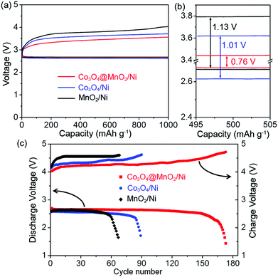
The electrocatalytic properties of the Co3O4@MnO2/Ni nanocomposite as a bifunctional catalyst for Li–O2 batteries were evaluated. Fig. 3a shows the first discharge/charge curves of the Li–O2 batteries with the Co3O4@MnO2/Ni, Co3O4/Ni, and MnO2/Ni cathodes at a current density of 100 mA g−1. The Co3O4@MnO2/Ni nanocomposite displays a significantly improved discharge voltage and a reduced charge voltage as shown in Fig. 3a and b. This results in a small discharge/charge voltage gap of 0.76 V, which is ca. 250 and 370 mV lower than those of the Co3O4/Ni and MnO2/Ni cathodes, respectively. The charge plateaus are corresponding to the decomposition of the discharge products, since the EMITFSI IL-based electrolyte has good electrochemical stability of up to 5.3 V.32 The round-trip efficiency based on the ratio of the discharge voltage to charge voltage is calculated to be 78% with a capacity limit of 1000 mA h g−1, higher than 74 and 69% of the Co3O4/Ni and MnO2/Ni cathodes as shown in Fig. 3b, respectively. It is notable that both the discharge and charge voltages of MnO2/Ni are higher than those of Co3O4/Ni. This suggests that the MnO2 is more active in the ORR process and Co3O4 is beneficial for the OER process. The integration of MnO2 and Co3O4 into the Co3O4@MnO2/Ni nanocomposite therefore presents a synergistic effect by showing higher discharge and lower charge voltages than the individual MnO2/Ni and Co3O4/Ni cathodes.
The cycling stability of the Li–O2 battery with the Co3O4@MnO2/Ni nanocomposite is displayed in Fig. 3c. It can be operated for 170 cycles with stable terminal discharge voltages above 2.0 V and charge voltages below 4.7 V at 300 mA g−1. This is in sharp contrast to the cycle life of 88 and 64 cycles for the individual Co3O4 and MnO2 cathodes, respectively. For references, the mechanical mixture of Co3O4 and MnO2 nanomaterials, which are composed of nanohorns and nanosheets, respectively, is displayed in Fig. S5, ESI.† They present similar morphologies to those in the Co3O4@MnO2/Ni nanocomposite, and have the same size dimensions. The as-synthesized Co3O4 and MnO2 with a weight ratio of 1![[thin space (1/6-em)]](https://www.rsc.org/images/entities/char_2009.gif) :
:![[thin space (1/6-em)]](https://www.rsc.org/images/entities/char_2009.gif) 1 were mechanically mixed with carbon (designated as Co3O4/MnO2/C) and coated onto a Ni foam. It leads to reduced reversibility (61 cycles), as presented in Fig. S6, ESI.† Compared to MnO2/Ni in Fig. 3, Co3O4/MnO2/C shows comparable discharge voltages and slightly lower charge overpotentials during the cycles. This suggests the function of Co3O4 in catalyzing the OER. The battery performance based on the presented Co3O4@MnO2/Ni nanocomposite is competitive by referring to the reported results on Co and/or Mn-based oxide electrocatalysts, as shown in Table S1.† This indicates the structural advantages of the Co3O4@MnO2/Ni nanocomposite: (i) homogeneous integration of the catalytically active sites of both MnO2 and Co3O4 for ORR/OER ensures good rechargeability, (ii) its vertical growth on a Ni foam enables facile electron transport and its function as a carbon- and binder-free cathode to restrain the carbon and binder involved side reactions, (iii) the void space between the Co3O4@MnO2 nanocomposites benefits electrolyte permeation and accommodation of the discharge product. Furthermore, an ether-based electrolyte, 1 M LiTFSI in tetraethylene glycol dimethyl ether (TEGDME), was also employed in the Li–O2 batteries with the Co3O4@MnO2/Ni nanocomposite. It presents 100 cycles of discharge and charge versus 170 cycles in the IL-based electrolyte counterpart, as depicted in Fig. S6, ESI.† The inferior performance of the TEGDME-based electrolyte may be attributed to slow decomposition of the electrolyte, which leads to formation of irreversible by-products, like lithium carbonate or carboxylates.33,34 The micro/nanostructure and bifunctional electrocatalytic activities of the carbon- and binder-free Co3O4@MnO2/Ni nanocomposite, as well as the stable IL-based electrolyte, ensure good electrochemical performance of the Li–O2 batteries.
1 were mechanically mixed with carbon (designated as Co3O4/MnO2/C) and coated onto a Ni foam. It leads to reduced reversibility (61 cycles), as presented in Fig. S6, ESI.† Compared to MnO2/Ni in Fig. 3, Co3O4/MnO2/C shows comparable discharge voltages and slightly lower charge overpotentials during the cycles. This suggests the function of Co3O4 in catalyzing the OER. The battery performance based on the presented Co3O4@MnO2/Ni nanocomposite is competitive by referring to the reported results on Co and/or Mn-based oxide electrocatalysts, as shown in Table S1.† This indicates the structural advantages of the Co3O4@MnO2/Ni nanocomposite: (i) homogeneous integration of the catalytically active sites of both MnO2 and Co3O4 for ORR/OER ensures good rechargeability, (ii) its vertical growth on a Ni foam enables facile electron transport and its function as a carbon- and binder-free cathode to restrain the carbon and binder involved side reactions, (iii) the void space between the Co3O4@MnO2 nanocomposites benefits electrolyte permeation and accommodation of the discharge product. Furthermore, an ether-based electrolyte, 1 M LiTFSI in tetraethylene glycol dimethyl ether (TEGDME), was also employed in the Li–O2 batteries with the Co3O4@MnO2/Ni nanocomposite. It presents 100 cycles of discharge and charge versus 170 cycles in the IL-based electrolyte counterpart, as depicted in Fig. S6, ESI.† The inferior performance of the TEGDME-based electrolyte may be attributed to slow decomposition of the electrolyte, which leads to formation of irreversible by-products, like lithium carbonate or carboxylates.33,34 The micro/nanostructure and bifunctional electrocatalytic activities of the carbon- and binder-free Co3O4@MnO2/Ni nanocomposite, as well as the stable IL-based electrolyte, ensure good electrochemical performance of the Li–O2 batteries.
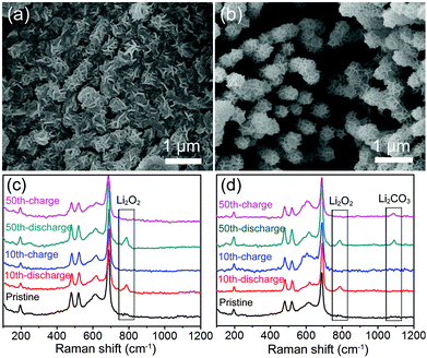
During the cycles, the discharged and charged Co3O4@MnO2/Ni nanocomposite cathodes were characterized by SEM and Raman spectroscopy, as displayed in Fig. 4. The Co3O4@MnO2/Ni cathode after the 10th discharge is shown to be covered by the mossy-like discharge product shown in Fig. 4a. It tends to aggregate in the void space between Co3O4@MnO2. In the following charge, the discharge product is reversibly decomposed to show the void space, and the porous structure of the Co3O4@MnO2/Ni cathode is recovered, as presented in Fig. 4b. The discharge product is identified to be Li2O2 by the Raman spectrum in Fig. 4c, and decomposed in the following charge with the disappearance of the characteristic Raman vibration band of Li2O2. In the 50th cycle of discharge and charge, the reversible formation and decomposition of Li2O2 at the Co3O4@MnO2/Ni cathode are monitored in the Raman spectra in Fig. 4c. But, at the Co3O4/MnO2/C cathode, in addition to the discharge product Li2O2, Li2CO3 is also detected by Raman spectroscopy in the 50th cycle as shown in Fig. 4d. In contrast, almost no Li2CO3 can be found at the Co3O4@MnO2/Ni cathode during the cycles as shown in Fig. 4c. Thus, the carbon- and binder-free in situ formed Co3O4@MnO2/Ni nanocomposite can effectively suppress the formation of lithium carbonate. The remarkable electrochemical performance of the Li–O2 battery based on the Co3O4@MnO2/Ni cathode originates from the integrated ORR and OER catalytic activities, efficient electron transfer through the networks of Co3O4 nanohorns grown on the Ni foam, and the porous micro/nanostructure that facilitates oxygen transport, electrolyte permeation, and accommodation of the discharge product Li2O2.
Conclusions
The porous Co3O4@MnO2/Ni nanocomposite was synthesized via a hydrothermal process and employed as a carbon- and binder-free cathode in rechargeable Li–O2 batteries by coupling with an ionic liquid-based electrolyte, 0.5 M lithium bis(trifluoromethylsulfonyl)imide (LiTFSI) in 1-ethyl-3-methylimidazolium bis(trifluoromethanesulfonyl)imide. The as-synthesized Co3O4@MnO2/Ni nanocomposite is featured as Co3O4 nanohorns coated with MnO2 nanosheets on a Ni foam, and ensures a small discharge/charge voltage gap of 0.76 V and a long cycle life of 170 cycles. This is derived from the integrated bifunctional catalytic activities towards both ORR and OER and the porous micro/nanostructures of the Co3O4@MnO2/Ni nanocomposite, which benefit the electron and oxygen transport and accommodation of Li2O2 as well as the ionic liquid-based electrolyte. The investigation suggests the promising application of this nanocomposite in Li–O2 batteries, and will give implications on the rational design of cheap, carbon- and binder-free catalysts for high-performance Li–O2 batteries.Acknowledgements
This work was supported by the NSFC (21231005 and 21322101) and the 111 Project (B12015).Notes and references
- F. Li, T. Zhang and H. Zhou, Energy Environ. Sci., 2013, 6, 1125 CAS.
- J.-S. Lee, S. T. Kim, R. G. Cao, N.-S. Choi, M. L. Liu, K. T. Lee and J. Cho, Adv. Energy Mater., 2011, 1, 34 CrossRef CAS.
- F. Cheng and J. Chen, Chem. Soc. Rev., 2012, 41, 2172 RSC.
- F. Cheng and J. Chen, Nat. Chem., 2012, 4, 962 CrossRef CAS PubMed.
- K. Zhang, X. Han, Z. Hu, X. Zhang, Z. Tao and J. Chen, Chem. Soc. Rev., 2015, 44, 699 RSC.
- Z. Peng, S. Freunberger, Y. Chen and P. Bruce, Science, 2012, 337, 563 CrossRef CAS PubMed.
- F. Li, R. Ohnishi, Y. Yamada, J. Kubota, K. Domen, A. Yamada and H. Zhou, Chem. Commun., 2013, 49, 1175 RSC.
- J. Xu, Z. Wang, D. Xu, F. Meng and X. Zhang, Energy Environ. Sci., 2014, 7, 2213 CAS.
- F. Li, D. Tang, T. Zhang, K. Liao, P. He, D. Golberg, A. Yamada and H. Zhou, Adv. Energy Mater., 2015, 5, 1500294 Search PubMed.
- X. Hu, X. Fu and J. Chen, Inorg. Chem. Front., 2015, 2, 1006 RSC.
- X. Han, T. Zhang, J. Du, F. Cheng and J. Chen, Chem. Sci., 2013, 4, 368 RSC.
- K. Zhang, X. P. Han, Z. Hu, X. L. Zhang, Z. Tao and J. Chen, Chem. Soc. Rev., 2015, 44, 699 RSC.
- C. Li, X. Han, F. Cheng, Y. Hu, C. Chen and J. Chen, Nat. Commun., 2015, 6, 7345 CrossRef CAS PubMed.
- J. Ming, Y. Wu, J.-B. Park, J. K. Lee, F. Zhao and Y.-K. Sun, Nanoscale, 2013, 5, 10390 RSC.
- F. Cheng, J. Shen, B. Peng, Y. D. Pan, Z. L. Tao and J. Chen, Nat. Chem., 2011, 3, 79 CrossRef CAS PubMed.
- W. Luo, S. Chou, J. Wang, Y. Zhai and H. Liu, Small, 2015, 11, 2817 CrossRef CAS PubMed.
- X. Han, F. Cheng, T. Zhang, J. Yang, Y. Hu and J. Chen, Adv. Mater., 2014, 26, 2047 CrossRef CAS PubMed.
- M. Hamdani, R. N. Singh and P. Chartier, Int. J. Electrochem. Sci., 2010, 5, 556 CAS.
- Y. Hu, T. Zhang, F. Cheng, Q. Zhao, X. Han and J. Chen, Angew. Chem., Int. Ed., 2015, 54, 4338 CrossRef CAS PubMed.
- D. Z. Kong, J. S. Luo, Y. L. Wang, W. N. Ren, T. Yu, Y. S. Luo, Y. P. Yang and C. W. Cheng, Adv. Funct. Mater., 2014, 24, 3815 CrossRef CAS.
- T. Zhang, F. Cheng, J. Du, Y. Hu and J. Chen, Adv. Energy Mater., 2015, 5, 1400654 Search PubMed.
- M. M. Ottakam Thotiyl, S. A. Freunberger, Z. Peng and P. G. Bruce, J. Am. Chem. Soc., 2013, 135, 494 CrossRef CAS PubMed.
- B. D. McCloskey, A. Speidel, R. Scheffler, D. C. Miller, V. Viswanathan, J. S. Hummelshøj, J. K. Nørskov and A. C. Luntz, J. Phys. Chem. Lett., 2012, 3, 997 CrossRef CAS PubMed.
- R. Black, S. H. Oh, J.-H. Lee, T. Yim, B. Adams and L. F. Nazar, J. Am. Chem. Soc., 2012, 134, 2902 CrossRef CAS PubMed.
- E. Nasybulin, W. Xu, M. H. Engelhard, Z. Nie, X. Li and J.-G. Zhang, J. Power Sources, 2013, 243, 899 CrossRef CAS.
- X. Han, Y. Hu, J. Yang, F. Cheng and J. Chen, Chem. Commun., 2014, 136, 13925 Search PubMed.
- L. Wang, J. Liu, S. Yuan, Y. Wang and Y. Xia, Energy Environ. Sci., 2016, 9, 224 CAS.
- J. Liu, J. Jiang, C. Cheng, H. Li, J. Zhang, H. Gong and H. Fan, Adv. Mater., 2011, 23, 2076 CrossRef CAS PubMed.
- W. Xiao, D. L. Wang and X. W. Lou, J. Phys. Chem. C, 2010, 114, 1694 CAS.
- F. Cheng, T. Zhang, Y. Zhang, J. Du, X. Han and J. Chen, Angew. Chem., Int. Ed., 2013, 52, 2474 CrossRef CAS PubMed.
- Y. T. Meng, W. Q. Song, H. Huang, Z. Ren, S. Y. Chen and S. L. Suib, J. Am. Chem. Soc., 2014, 136, 11452 CrossRef CAS PubMed.
- B. Garcia, S. Lavallée, G. Perron, C. Michot and M. Armand, Electrochim. Acta, 2004, 49, 4583 CrossRef CAS.
- X. Han, F. Cheng, C. Chen, Y. Hu and J. Chen, Nano Res., 2015, 8, 156 CrossRef CAS.
- F. Li, D. Tang, Z. Jian, D. Liu, D. Golberg, A. Yamada and H. Zhou, Adv. Mater., 2014, 26, 4659 CrossRef CAS PubMed.
Footnote |
| † Electronic supplementary information (ESI) available: Synthesis and electrochemical characterization details, additional SEM and TEM images, EDS data and cyclic stability in different electrolytes. See DOI: 10.1039/c6qi00066e |
| This journal is © the Partner Organisations 2016 |

