Preparation and characterization of nano-sized PS@Pd core–shell architectures with a one-pot method
Nianchun Zhang*a,
Bin Guob,
Hong Liua,
Ping Liua,
Guihua Liuc and
Jinquan Chengc
aCollege of Material Science and Engineering, South China University of Technology, Guangzhou 510641, P. R. China. E-mail: cenczhang@scut.edu.cn
bMicroelectronics, School of Materials and Energy, Guangdong University of Technology, Guangzhou 510006, P. R. China
cShenzhen Center for Disease Control and Prevention, Shenzhen 518020, P. R. China
First published on 10th December 2015
Abstract
Monodispersed and nano-sized Pd (palladium) coated PS (polystyrene) core–shell architectures have been prepared successfully by a facile, green and fast one-pot method, in which an acrylic acid and vitamin C were used for the carboxyl-functionalization of the polymer beads and as a reducing agent, respectively. The structures and morphologies of the PS@Pd core–shell architectures were characterized by X-ray diffraction (XRD), transmission (high resolution) electron microscopy (TEM, HRTEM), X-ray photoelectron spectroscopy (XPS) and so on. The results demonstrated that the Pd nanoparticles were deposited on the surface of the PS sphere beads, and the Pd nanoparticles were homogeneous and monodispersed. The results also indicated that the diameter of the Pd shell was 5 ± 1.2 nm and the PS@Pd core–shell architectures were 80 ± 3.5 nm. So this one-pot preparation method provides developmental direction to fabricate all kinds of polymer@nonmetal core–shell architectures. In addition, the PS@Pd showed improved electrocatalytic activity for formic acid oxidation in comparison with commercial Pd nanoparticles through controlling the surface structures.
1. Introduction
Noble metal nanoparticles can be widely applied in optical, electronic, catalytic and conducting applications and antibacterial treatments because of their unusual properties and promising potential.1,2 Noble Pd (palladium) nanoparticle based catalysts are vital for fuel cells, sensors and the petroleum and automotive industries due to their high catalytic activity and stability.3 Over the past decade, the design of novel Pd nanomaterials with unique properties has attracted great attention due to the potential for new applications and improvement of current applications.4 Palladium as a relatively abundant resource has been intensively studied as an alternative electrocatalyst for its desirable activity toward the oxygen reduction reaction.5,6 However, because Pd is a precious metal of the platinum group metals, most of the recent efforts have focused on decreasing Pd utilization through increasing the catalytic efficiency of its catalysts. It has also been found that using Pd based composites could improve the catalytic activity of Pd.7Core–shell architectures can play a synergistic role to affect the thermodynamics and/or the kinetics.8 PS (polystyrene) is an effective template for the preparation of composite materials because of the ease of surface functionalization and size variations. The preparation of polymer@metal core–shell architectures is an ongoing challenge in new materials preparation.9,10
The most common methods for the preparation of polymer@metal core–shell structures are electroless plating, deposition of a microwave absorbing coating and in situ deposition.11–13 There are few reports on the preparation of Pd nanocomposites using simple strategies, such as sequential condensation, decarboxylation, Heck reactions, nitration, reduction of polystyrene nanospheres and using polystyrene spheres as a template.14–16 In the past, polymer@Pd has been prepared through using supercritical carbon dioxide, sodium borohydride and hydrazine hydrate.17 All these chemicals pose potential environmental and biological risks. In the wake of increasing awareness about the environment, this has led researchers to focus on green preparation approaches. Utilization of nontoxic chemicals, environmentally benign solvents and renewable materials are some of the key issues that merit important consideration in a green synthesis strategy.18 However, there have been reports on the preparation of Pd nanoparticles using environment-friendly vitamin C as the reducing agent.
In this work, we report a facile, green and fast one-pot method for the fabrication of PS@Pd core–shell architectures by using acrylic acid as a carboxyl-group source and vitamin C as a reducing agent. With gentle heating, this system is a mild, renewable, inexpensive and nontoxic reducing agent. The structure and morphology of the PS@Pd core–shell architectures are also investigated.
2. Experimental
2.1 Materials
Styrene (St, 98%), polyvinylpyrrolidone (PVP, K30), acrylic acid (AA, 99.9%) and azodiisobutyronitrile (AIBN, 99.5%) were purchased from Sigma-Aldrich. Vitamin C was obtained from Tianjing Products Inc. Other solvents and reagents were purchased from the Guangzhou Chemical Company. All chemicals were used as received without further purification.2.2 Preparation of PS@Pd core–shell architectures
The typical procedure for preparing the PS@Pd core–shell architectures was as follows: firstly, prior to use, the styrene was treated with 10 wt% NaOH solution in a separation funnel and rinsed three times in the funnel in order to remove the antipolymerizer. The sealed purified sample was stored at 4 °C until required. Secondly, 0.1 g of PVP, 0.5 g of AIBN, 0.3 g of AA, 80 mL of ethanol and 20 mL of H2O were added to a 300 mL three-necked flask. The above mixture was stirred until transparent and homogeneous. Then 10 mL of styrene was added under a nitrogen atmosphere and rapid stirring. The above emulsion solution was heated to 70 °C and polymerized for 3 h. Thirdly, 10 mL of a fresh 0.1 mol L−1 palladium chloride solution was added to the above solution and stirring was continued for another 30 min at room temperature. Finally, 40 mL of a 0.1 mol L−1 vitamin C aqueous solution was added dropwise into the mixed solution and the mixture was kept at 50 °C for 2 h. Then the obtained precipitates were centrifuged at 8000 rpm and 5 °C for 15 min, washed several times with distilled water, and dried under vacuum at 60 °C for 2 h.2.3 Electrode preparation
The nano-sized PS@Pd and commercial Pd nanoparticles were electrodeposited on a glassy carbon rod electrode in a 0.2 mM PdCl2 + 0.5 M H2SO4 solution at room temperature. Firstly, the glassy carbon rod electrode was subjected to a potential step from 1.20 V to −0.10 V and stayed there for 20 ms to produce Pd nuclei. A square wave potential to the lower potential limit of 0.30 V and upper potential limit of 0.70 V at 100 Hz was then used to grow Pd nuclei into PS@Pd and commercial Pd nanoparticles.2.4 Measurements
The crystallinity of the samples was determined with a MSAL-XD2 X-ray diffractometer (XRD) with Cu Kα radiation (40 kV, 20 MA, λ = 1.54051 Å). Fourier transform infra-red spectroscopy (FTIR) spectra were obtained with a spectrophotometer (EQUINOX-55, Thermo Electron Corporation). The high-resolution transmission electron microscope (HRTEM) images, selected area electron diffraction (SAED) measurements and energy-dispersive X-ray spectroscopic (EDX) measurements were taken with a JEM-2010F instrument, using an accelerating voltage of 200 kV. The particle size distribution was measured by dynamic light scattering (DLS, Malvern Instr., UK). The electrochemical properties of the catalysts were measured in a three-electrode cell at room temperature using a potentiostat (Eco Chemie, AUTOLAB).2.5 Electrocatalytic activity test
Ag/AgCl (in saturated KCl) was used as a reference electrode. The glassy carbon electrode as a working electrode was polished with Al2O3 paste and then washed in deionized water. The catalyst ink was prepared with ultrasonic dispersing catalyst powders in an appropriate amount of Millipore water. Prior to the electrocatalytic activity test for methanol oxidation, the glassy carbon rod electrode loaded with PS@Pd and commercial Pd nanoparticles was electrochemically cleaned by continuous potential cycling between −0.20 and 1.20 V at 50 mV s−1 until a stable cyclic voltammogram (CV) curve was obtained. The CVs of the electrocatalysts for formic acid electrooxidation were obtained from −0.2 to +1.2 V in 0.5 M H2SO4 + 0.5 M methanol.3. Results and discussion
3.1 Characterization of morphology and structure
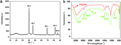
Fig. 1a displays the XRD patterns of the PS@Pd core–shell structure. The data for the core–shell architectures peaks at 40.1°, 46.7°, 68.1°, 82.1° and 86.6° corresponding to the (111), (200), (220) and (311) crystal planes of Pd, respectively. This indicates that the prepared Pd in this study possesses a face-centered cubic structure. The curved peak observed at 20° indicates that PS did not form a regular crystal structure. It can be seen from Fig. 1b that the observed strong FTIR absorption bands at 3012, 2885, 1460, 1400 and 690 cm−1 agree with PS standard absorption bands and the absorption bands centered at 3400 cm−1 are attributed to –COO−. After coating with these Pd nanoparticles, the bands at 3012 and 2885 cm−1 gradually weaken, which belong to the asymmetric and symmetric stretching vibrations of –CH2. The intensity peak at 690 cm−1, which may result from the deformation vibration of C–H of the benzene ring, has been reduced significantly. The results also show that PS and Pd had formed composite materials.Fig. 2a shows TEM images of the PS@Pd core–shell architectures and their morphologies are almost uniformly spherical. The size of the PS@Pd core–shell architectures is 80 ± 3.5 nm. The images also display that the homogeneous and monodispersed Pd nanoparticles are deposited on the PS bead matrix. Fig. 2b shows a magnified TEM image of the PS@Pd core–shell architectures and the details of Pd shell nanoparticles can be seen. The electrostatic interactions of the negatively charged PS–COO− can accelerate the Pd nanoparticle deposition, which could be proved by the result that the Pd nanoparticles were almost completely adsorbed onto the PS surface.19 The hydrodynamic diameter distribution of PS@Pd is shown in Fig. 2c, and the nanoparticles are smaller with a narrower distribution. The image also shows that the PS@Pd core–shell architectures are monodispersed with a polydispersity index of 0.024 and an average diameter of 80 nm.
 | ||
| Fig. 2 TEM images of (a) PS@Pd, (b) magnified TEM image of PS@Pd, and (c) size distribution of PS@Pd. | ||
Fig. 3a displays the HRTEM image analysis of the PS@Pd core–shell architectures, and the Pd nanoparticle shells are 5 ± 1.2 nm. The lattice fringes are shown in Fig. 3b. The distance between the adjacent fringes in the particle’s shell is 0.225 nm, which fits well with the distance between the (111) planes of the face centered cubic Pd. The point pattern of the corresponding SAED (Fig. 3c) further confirms the single crystalline nature of the Pd. The EDX (Fig. 3d) analysis of the PS@Pd nanoparticles shows that the amounts of the constituent elements are 82.7% (C) and 14.8% (Pd). The other peaks such as Cu and O are attributed to the copper grid.
 | ||
| Fig. 3 (a) HRTEM image of PS@Pd, (b) lattice fringe HRTEM image of PS@Pd, (c) SAED analysis of PS@Pd, and (d) EDX analysis of PS@Pd. | ||
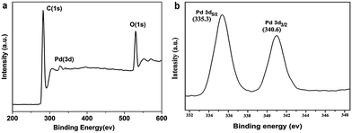
As can be seen from Fig. 4a, the peaks of the Pd and C elements are obviously found in the survey scan of the XPS spectrum of the PS@Pd core–shell architectures. The XPS analysis shows that the constituent weights are 83.1 wt% C and 15.1 wt% Pd in PS@Pd. The amount of Pd is 15.1 wt% calculated from the XPS analysis, and the weight percentages of Pd investigated with XPS and EDX (14.8 wt%) show similar results compared to different characterization methods. In order to investigate the chemical state of the Pd nanoparticles, the high resolution XPS spectrum of Pd 3d is recorded. Fig. 4b shows the Pd 3d spectrum of two individual peaks which can be attributed to the Pd 3d5/2 and Pd 3d3/2 binding energies. The values of Pd 3d5/2 and Pd 3d3/2 were 335.3 and 340.6 eV, respectively, which can be attributed to the metallic Pd(0) state.20 During this procedure, Pd2+ ions are adsorbed onto the surface of the PS beads which are functionalized with negatively charged –COO− groups due to electrostatic attraction. All of the Pd2+ ions are completely reduced to Pd0 by using vitamin C as a reducing agent.
3.2 The mechanism for the formation of the PS@Pd core–shell architectures
The formation of the PS@Pd core–shell architectures is schematically represented in Fig. 5, which schematically displays an overall procedure for preparation of the core–shell architectures. From the above results, the Pd nanoparticles could deposit on the negatively charged PS. The surface electrically charged polystyrene beads are prepared by grafting with –COOH groups. When the PS–COOH groups are deprotonated, charged PS–COO− can be obtained. The PS–COO− has negative charges on the surface of water, which facilitates [Pd]2+ in attracting PS–COO− by electrostatic attraction.The Pd nanoparticles are synthesized by an in situ reduction method and the obtained Pd nanoparticles can serve as nucleation sites.
The mechanism for the formation of the PS@Pd core–shell architectures is as follows. Firstly, the positively charged Pd2+ ions are attracted to the negatively charged [PS–COO]− surface by electrostatic attraction. The L-ascorbic acid serves as a stable electron donor in its interactions, and is converted into the radical ions called semidehydroascorbic acid and dehydroascorbic acid.21 Then the obtained Pd seeding is used as the nucleation center for forming the silver nanoparticles afterwards. The more the Pd2+ ions are attracted onto PS, the more Pd nanoparticles that deposit on the surfaces of PS particles.
3.3 Cyclic voltammogram of the PS@Pd core–shell architectures
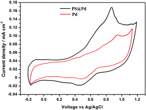
The cyclic voltammograms of the PS@Pd (black line) architectures and commercial Pd catalyst (red line) recorded in 0.5 M H2SO4 solution. The CVs of PS@Pd and commercial Pd catalysts for methanol oxidation are shown in Fig. 6. | ||
| Fig. 6 CVs of commercial Pd and PS@Pd for methanol oxidation in 0.5 M H2SO4 with a scan rate of 50 mV s−1. | ||
In the comparison of the CVs, the spherical PS@Pd core–shell catalysts show more negative peak potential (0.820 V) for oxidation than 0.960 V for commercial Pd. The data also shows that the structure controlled Pd can be a promising catalyst for formic acid electrooxidation.22 Thus, by combining the electrochemical data and structural analyses, it is concluded that the core–shell PS@Pd can be a promising candidate for formic acid oxidation in comparison with commercial Pd.
4. Conclusions
In summary, PS@Pd core–shell architectures have been successfully prepared through a facile, green and fast one-pot method. The preparation method was efficient, simple and environmentally benign. The experimental results indicate that the carboxyl-group containing acrylic acid and vitamin C played an important role in the formation of the core–shell architectures. The core–shell architectures had a spherical structure in a size of 80 ± 3.5 nm and the diameter of the Pd shell was 5 ± 1.2 nm. The Pd nanoparticle shells were homogeneous and monodispersed. The PS@Pd core–shell architectures showed improved electrocatalytic activity for formic acid oxidation in comparison with commercial Pd. Therefore, the unique PS@Pd core–shell materials are also expected to find potential applications in many areas such as electrocatalysis, fuel cells and sensors.Acknowledgements
This project is supported by the China Postdoctoral Science Foundation funded project (No. 2014M562182) and the Fundamental Research Funds for the Central Universities (No. 2014ZM0058).Notes and references
- S. Ikurumi, S. Okada, K. Nakatsuka, T. Kamegawa, K. Mori and H. Yamashita, J. Phys. Chem. C, 2014, 118, 575–581 CAS.
- R. Wu, Y. P. Zhang, R. J. Hong, S. Q. Lai, C. Ye and J. Q. Hu, Mater. Lett., 2012, 89, 236–239 CrossRef CAS.
- Y. Shao, J. Liu, Y. Wang and Y. Lin, J. Mater. Chem., 2009, 19, 46–59 RSC.
- X. Zhao, S. Chen, Z. C. Fang, J. Ding, W. Sang, Y. C. Wang, J. Zhao, Z. M. Peng and J. Zeng, J. Am. Chem. Soc., 2015, 137, 2804–2807 CrossRef CAS PubMed.
- Z. Y. Zhang, T. Sun, C. Chen, F. Xiao, Z. Gong and S. Wang, ACS Appl. Mater. Interfaces, 2014, 6, 21035–21040 CAS.
- M. Shao, P. Liu, J. Zhang and R. Adzic, J. Phys. Chem. B, 2007, 111, 6772–6775 CrossRef CAS PubMed.
- Y. Suo, L. Zhuang and J. Lu, Angew. Chem., Int. Ed., 2007, 46, 2862–2864 CrossRef CAS PubMed.
- M. M. Zhang, T. H. Ngo, N. I. Rabiah, T. P. Otanicar, P. E. Phelan, R. Swaminathan and L. L. Dai, Langmuir, 2014, 30, 75–82 CrossRef CAS PubMed.
- N. C. Zhang, X. Yu and J. Q. Hu, Mater. Lett., 2014, 125, 120–123 CrossRef CAS.
- C. Rungsima, S. Wirasak and C. Arkadiusz, RSC Adv., 2014, 4, 30648–30653 RSC.
- H. Y. Hsueh, Y. C. Huang, R. M. Ho, C. H. Lai, T. Makida and H. Hasegawa, Adv. Mater., 2011, 23, 3041–3046 CrossRef CAS PubMed.
- D. H. Nam, S. J. Lim, M. J. Kim and H. S. Kwon, RSC Adv., 2014, 4, 10212–10215 RSC.
- Y. Jung, N. Singh and K. S. Choi, Angew. Chem., Int. Ed., 2009, 48, 8331–8334 CrossRef CAS PubMed.
- A. K. Shil and P. Das, RSC Adv., 2015, 5, 24859–24863 RSC.
- G. J. Lan, X. M. Zhang, X. M. Zhang, M. R. Li, Y. Li and Q. H. Yang, RSC Adv., 2015, 5, 35730–35736 RSC.
- Z. Yan, Y. Gu, W. Wei, Z. Jiang, J. Xie and P. K. Shen, Fuel Cells, 2015, 15, 256–261 CrossRef CAS.
- K. H. Tian, C. Y. Liu, H. J. Yang and X. Y. Ren, Colloids Surf., A, 2012, 397, 12–15 CrossRef CAS.
- M. R. Shantamal and J. S. Arora, RSC Adv., 2014, 4, 20323–20333 RSC.
- J. Zhi, D. P. Song, Z. W. Li, X. Leia and A. G. Hu, Chem. Commun., 2011, 47, 10707–10709 RSC.
- Y. Sohn, D. Pradhan and K. T. Leung, ACS Nano, 2010, 4, 5111–5120 CrossRef CAS PubMed.
- N. C. Zhang, X. Yu, J. Q. Hu, F. Xue and E. Y. Ding, RSC Adv., 2013, 33, 13740–13747 RSC.
- Y. W. Lee, J. K. Oh, H. S. Kim, J. K. Lee, S. B. Han, W. J. Choi and K. W. Park, J. Power Sources, 2010, 195, 5896–5901 CrossRef CAS.
| This journal is © The Royal Society of Chemistry 2016 |


