Poly(lactic acid) melt-spun fibers reinforced with functionalized cellulose nanocrystals
A. Mujica-Garciaab,
S. Hooshmandc,
M. Skrifvarsd,
J. M. Kennyab,
K. Oksmanc and
L. Peponi*b
aDipartimento di Ingegneria Civile e Ambientale, Università di Perugia, Italy
bInstituto de Ciencia y Tecnología de Polímeros, ICTP-CSIC, Spain. E-mail: lpeponi@ictp.csic.es
cDivision of Materials Science, Composite Centre Sweden, Luleå University of Technology, Luleå, Sweden
dSchool of Engineering, University of Borås, Borås, Sweden
First published on 7th January 2016
Abstract
Poly(lactic acid)-cellulose nanocrystals (PLA/CNC) nanocomposite fibers with 1% weight fraction of nanocrystals were prepared via melt-spinning. In order to improve the compatibility between PLA and the CNC, PLLA chains were grafted onto the CNC surface using a “grafting from” reaction. For comparison, melt-spun PLA fibers and nanocomposites with unmodified CNC were also prepared. The morphology and thermal and mechanical properties of the fibers with different draw ratios were determined. The results of this research show that the surface modification together with drawing resulted in improved fiber properties, which are expected to depend on the alignment of the CNC and PLA molecular chains. The modification is also expected to lead to a flexible interface, which leads to more stretchable fibers. The main conclusion is that PLLA grafting is a very promising approach to improve the dispersion of CNC in PLA, thus creating interfacial adhesion between the phases and making it possible to spin fibers that can be drawn with improved mechanical performance.
Introduction
Nowadays, the use of high performance materials is required in numerous application fields, from aerospace to the biomedical sector and the demand for new multifunctional materials is a key factor in both research centres and industry.1 Moreover, due to the strong increase in the consumption of polymeric-based materials, the use of biodegradable polymers is required to obtain environmental-friendly materials to be used in daily life products. At the same time, attention is focused on the manufacturing and processing conditions of biodegradable polymers. For example, scaffolds created from biodegradable polymers are fabricated using particulate leaching, textile technologies, or three-dimensional (3D) printing techniques.2 In this regard, the use of polymeric fibers to form a biodegradable scaffold provides several advantages for tissue-engineering applications because of their large surface area-to-volume ratio. Moreover, they present a high potential to provide ideal living conditions for cells due to the ability of the fibers to be processed into a variety of shapes and sizes, thus achieving the required mechanical and biological properties.3,4,7Currently, poly(lactic acid) (PLA), which is an aliphatic polyester, represents the most representative biodegradable and biobased polymer in the market due to its cost-competitiveness with respect to conventional not biodegradable polymers.5,6 In particular, PLA is a thermoplastic biodegradable polyester of great interest from the environmental point of view due to its thermoplastic processability, good biocompatibility, biodegradability and good mechanical properties.7–9 Some limitations of PLA are its poor toughness, slow degradation rate,10 and low thermal stability, which limit its processing temperature.6,10,11
In order to improve the properties of PLA, the preparation of nanocomposite materials by the addition of nanoparticles to the PLA matrix is a possibility that has been largely developed over the past years.12–14 Among the nanoparticles, the attraction for cellulose nanocrystals (CNC) to be used as nanoreinforcements in the PLA matrix has greatly increased recently.15–20
CNC are rod-like nanoparticles that are obtained by the acid hydrolysis of cellulose fibers, which have a diameter in the range of 3–20 nm and length in the range of 100–600 nm, depending on the cellulose source.5 Since they are derived from cellulose, CNC offer many advantages such as high reactivity, renewability, biodegradability, and natural abundance.1 In addition, CNC can be used as a nanoreinforcement in composite materials based on biopolymers, such as PLA, due to their suitable qualities as a consequence of the combination of nanoscale dimensions and high aspect ratio together with their good mechanical properties. In this way, fully biobased nanocomposites can be obtained.15 However, polymer/cellulose nanocomposites have a drawback relative to the poor dispersion of cellulose in non-polar media because of their polar surface,19 hence there is interfacial incompatibility between the hydrophobic PLA matrix and hydrophilic CNC, which causes CNC to aggregate.5,21 As a consequence of the abovementioned issues, the preparation of CNC-based nanocomposites by extrusion can be considered as an alternative to improve their compatibility. Oksman et al.19 studied the feasibility of using extrusion to process nanocellulose-based PLA nanocomposites. They prepared a suspension of CNC, which was pumped into the polymer melt during the extrusion process. CNC were obtained previously from commercial microcrystalline cellulose (MCC). MCC was treated with N,N-dimethylacetamide (DMAc) containing lithium chloride (LiCl) to swell and partially separate the CNC. The dispersion of CNC within the PLA matrix was appreciable. The mechanical properties of the nanocomposites were improved compared to the reference material. However, DMAc/LiCl caused the composites to degrade when processed at high-temperatures.
Another approach to improve their dispersion is the grafting of polymer chains on the surface of CNC by a covalent linkage between CNC and the grafted polymer chains.22 Thus, the grafted polymer chains act as a compatibilizer between the CNC and the polymeric matrix, which improves the interfacial adhesion and as a result, optimizes the compatibility between the polymer and the CNC.1 The improvement of the compatibility between PLA and CNC grafted with poly(L-lactic acid) (PLLA) was studied by Navarro-Baena et al.23 They prepared films of poly(ester-urethane) based on the PCL–PLLA triblock-copolymer with functionalized and unfunctionalized CNC and reported an increase in their mechanical and shape memory properties when grafted CNC were used.
Some techniques can be used to obtain PLA nanocomposites fibers such as melt spinning8,24–26 solution spinning27,28 and electrospinning.6,29–31 From an environmental point of view, melt spinning is a suitable technique to prepare polymeric fibers. It is a solvent-free process that provides a more environmentally friendly processing method, in which there is no need for solvent removal and high throughput and high take-up speeds can be achieved. As a consequence, the melt-spinning process can be considered as the main convenient commercial method to produce large quantities of fibers in industries.4 Moreover, processing conditions strongly influence the final properties of fibers, for example, the tendency of PLA melt-spun fibers to crystallize. In fact, crystallization can be induced in the fiber axis by drawing the fiber during its formation4 thus considering that the drawing of the fiber can orient the polymer chains in the direction of the fiber axis. Consequently, a wide range of mechanical properties can be achieved for fibers by adjusting the melt draw ratio, MDR.4 However, PLA shows a tendency to undergo thermal degradation in the molten state, due to the scission of polymer chains, which produces melt-spun fibers with poor mechanical properties. Its degradation is dependent on time, temperature, low-molecular weight impurities and catalyst concentration.8,32
In recent years, the morphologies, thermal and mechanical properties of melt-spun PLA fibers have been studied.7,33,34 Persson et al.4 prepared PLA fiber-based scaffold architectures using the melt-spinning technique and solid-state drawing. The influence of process variables, such as draw ratios and temperatures, on the properties of the fibers was studied in the preparation of monofilament and multifilament fibers. They reported that physical properties, such as crystallinity, mechanical strength and ductility, can be largely controlled by the drawing process by taking into account the solid-state drawing and drawing temperatures.
Only a few studies regarding melt-spun PLA/CNC nanocomposite fibers have been found in the literature. John et al.35 prepared melt spun PLA/CNC nanocomposite fibers through the melt-compounding of PLA and CNC using a twin-screw extruder, in which compounded pellets were generated as the feed for melt spinning. They reported that PLA/CNC fibers showed an increase of surface roughness and aggregations of CNC. Moreover, the fiber stiffness was not changed by the addition of the CNC, which is probably due to the aggregation of CNC and the poor interphase between the matrix and CNC. In another study reported by Blaker et al.,36 melt-spun fibers of a PLA/CNC nanocomposite were prepared and neat and esterified bacterial cellulose were compared. They showed that high fiber diameters were produced when CNC was added, as a consequence of the increase in the viscosity of the polymer melt and in the reduction of the draw-ratio of the fibers. In addition, they reported that the presence of CNC also enhanced the nucleation and growth of crystals and thus an improvement in mechanical properties.
In this study, melt-spun fibers of PLA and its nanocomposites were successfully prepared in two steps. First, PLA nanocomposites reinforced with neat and functionalized CNC were prepared and then the fibers were obtained by melt-spinning process. The effect of the addition of CNC, both neat and grafted with PLLA, on the properties of the PLA melt-spun fibers was determined, with attention focused on the fiber drawing effect on the final properties of the melt-spun fibers. In order to characterize the CNC grafted with PLLA, vibrational spectroscopy techniques, such as Fourier transform infrared and Raman spectroscopy, were used, as well as thermogravimetric analysis to determine the amount of CNC and PLA in the melt-spun fibers. The Molau test was used to study the interfacial interaction between the PLA matrix and functionalized CNC. Moreover, the dispersion of the nanocrystals was controlled by birefringence. The influence of temperature reached in the compounder on the possible degradation process of the PLA matrix was examined via gel permeation chromatography (GPC). The influence of drawing and the incorporation of CNC (grafted and neat) on the final structure and properties of the melt-spun fibers was examined by scanning electron microscopy, thermogravimetric analysis, wide-angle X-ray diffraction, differential scanning calorimetry and tensile testing.
Experimental
Materials
Poly(lactic acid) (PLA 3051D) was supplied by NatureWorks (EE.UU.), which had 3% of D-lactic acid monomer and a molecular weight (Mn) of 110.000 g mol−1.Cellulose nanocrystals (CNC) were synthesized by the acid hydrolysis of commercial cellulose microcrystals. Microcrystalline cellulose (MCC) powder was purchased from Sigma Aldrich. Moreover, in order to increase the compatibility between the hydrophobic polymer and the hydrophilic nanocrystals, surface modifications of CNC were carried out via a “grafting from” reaction, wherein PLLA chains were grafted onto the CNC external surface to obtain CNC-g-PLLA.
L-Lactide, stannous octoate (Sn(Oct)2), chloroform (CHCl3), toluene, dichloromethane and N,N-dimethylformamide (DMF) were purchased from Sigma Aldrich (Spain). 1,4-Dioxane was supplied by VWR International.
We refer to the fibers obtained from commercial polymer as PLA fibers and to the polymeric chains grafted onto the CNC surface as PLLA, which was obtained due to the ring opening polymerization (ROP) of L-lactide.
Synthesis of cellulose nanocrystals
CNC were prepared following the method reported in previous work by the acid hydrolysis of commercial cellulose microcrystals.37,38 First, 20 g of MCC and 175 mL of sulphuric acid solution (64% (w/w)) were mixed in a 250 mL three-neck round-bottom flask and homogenised with a mechanical stirrer and hydrolysis was carried out at 45 °C for 30 min in the flask. The obtained product was diluted in 4 L of deionised water to stop the hydrolysis reaction. Next, to remove the excess acid, the suspension was centrifuged, and 1 L of CNC suspension was obtained, which was dialysed for 5 days for neutralization. To purify the suspension, ion exchange resin (Dowex Marathon MR-3 hydrogen and hydroxide form) was added and stirred for 24 hours and then removed by filtration. The pH of the CNC suspension was adjusted to around 9.0 using a 1.0% NaOH buffer solution.38 Finally, the CNC suspension was sonicated in order to obtain a stable suspension of the nanocrystals, which was stored in a fridge at 3 °C to avoid bacterial growth.CNC functionalization with PLLA chains
Surface modification of the CNC was carried out via a “grafting from” reaction, in which PLLA chains were grafted onto the CNC surface via the ROP of L-LA, using the superficial hydroxyl groups of the CNC as the initiator. The modification of cellulose was performed according to a previous study reported by Navarro-Baena et al.23 The aqueous suspension of CNC was solvent-exchanged with acetone, dichloromethane and dried toluene by centrifugation and re-dispersion cycles. The modification reaction was carried out in a three-neck round-bottom flask equipped with a condenser and a calcium chloride tube, and the system was kept under a nitrogen atmosphere. The monomer was dissolved in dry toluene for 10 min at 50 °C and after that, the CNC dispersed in toluene was added.The solution was heated to 80 °C and 0.2 g of Sn(Oct)2, which was the catalyst, was added to the mixture using a syringe. After 24 hours, the product was dissolved in toluene to recover it. After that, centrifugation–redispersion cycles using methanol, ethanol and acetone were carried out to remove the un-reacted monomer and the non-grafted polymer. Finally, the PLLA functionalized CNC, which is named CNC-g-PLLA, was dissolved in CHCl3 for storage.
Nanocomposite preparation
CNC and CNC-g-PLLA nanocomposites based on the PLA matrix were prepared following a similar procedure to that described by Persson et al.3 First, PLA was dissolved in 1,4-dioxane to form a 10 wt% solution, which was magnetically stirred for 24 h at room temperature. At the same time, CNC and CNC-g-PLLA were dispersed separately (1 wt%) in DMF and magnetically stirred for 2 h and ultrasonicated for 2 min. In the second step, to achieve a homogeneous dispersion of the CNC in the dissolved PLA matrix, both the polymer solution and the CNC suspensions were mixed, stirred (2 h) and then sonicated (2 min) to form nanocomposites, which had a 1% weight fraction of CNC in the final composition. Finally, PLA/CNC and PLA/CNC-g-PLLA nanocomposite microspheres were prepared using the solvent evaporation method based on thermally induced phase separation (TIPS).36 In particular, microspheres were formed by the dropwise addition of the mixtures in liquid nitrogen to avoid agglomeration of the nanoparticles by rapid quenching, followed by solvent removal using freeze-drying at −50 °C for 24 h. The same process was performed to prepare neat PLA microspheres as a reference material and three different samples were prepared (PLA, PLA/CNC and PLA/CNC-g-PLLA).Melt-spinning and melt drawing
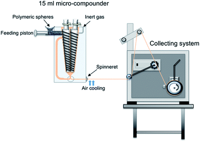
Nanocomposite fibers were prepared by the melt-spinning of neat PLA microspheres, as well as PLA/CNC and PLA/CNC-g-PLLA, in batch mode, using a 15 mL twin-screw micro-compounder, DSM Xplore (Geleen, The Netherlands), equipped with a 0.5 mm single hole spinneret.The experiment was carried out in speed control mode with the rotation speed varied between 50 and 80 rpm with a 5 min residence time at 190 °C in an argon atmosphere.
The fibers were cooled using a gentle air flow and collected using different rates on a rotating take-up roll and subsequently the melt draw ratio (MDR) was calculated based on eqn (1):
| MDR = (D0/D)2 | (1) |
| Samples codes | PLA (wt%) | CNC (wt%) | CNC-g-PLLA (wt%) | Take-up velocitya (cm min−1) | Diameterc (μm) | MDR |
|---|---|---|---|---|---|---|
| a Take-up velocity was calculated based on the bobbin's circumference and number of rotations per minute.b In the case of the as-spun fibers, the take-up velocity was varied to avoid stretching of the fibers.c Diameter of the fibers was measured by a micrometer. | ||||||
| PLAAS | 100 | 0 | 0 | 30–100b | 358 ± 4 | 2 |
| PLAMDR1-A | 100 | 0 | 0 | 1125 | 120 ± 6 | 17 |
| PLAMDR1 | 100 | 0 | 0 | 2025 | 80 ± 1 | 39 |
| PLAMDR2-A | 100 | 0 | 0 | 3150 | 63 ± 3 | 63 |
| PLAMDR2 | 100 | 0 | 0 | 4500 | 53 ± 3 | 89 |
| PLA/CNCAS | 99 | 1 | 0 | 30–100b | 491 ± 7 | 1 |
| PLA/CNCMDR1-A | 99 | 1 | 0 | 1125 | 181 ± 14 | 8 |
| PLA/CNCMDR1 | 99 | 1 | 0 | 2025 | 79 ± 14 | 40 |
| PLA/CNCMDR2-A | 99 | 1 | 0 | 3150 | 60 ± 13 | 69 |
| PLA/CNCMDR2 | 99 | 1 | 0 | 4500 | 47 ± 5 | 113 |
| PLA/CNC-g-PLLAAS | 99 | 0 | 1 | 30–100b | 471 ± 80 | 1 |
| PLA/CNC-g-PLLAMDR1-A | 99 | 0 | 1 | 1125 | 268 ± 23 | 3 |
| PLA/CNC-g-PLLAMDR1 | 99 | 0 | 1 | 2025 | 122 ± 17 | 17 |
| PLA/CNC-g-PLLAMDR2-A | 99 | 0 | 1 | 3150 | 86 ± 4 | 34 |
| PLA/CNC-g-PLLAMDR2 | 99 | 0 | 1 | 4500 | 55 ± 6 | 83 |
Characterization
Several techniques were used to characterize the melt-spun fibers based on PLA and PLA reinforced with neat and functionalized CNC. First, the neat CNC and functionalized CNC-g-PLLA were characterized by vibrational spectroscopy techniques in order to verify their functionalization. Fourier transform infrared spectroscopy (FTIR) was performed on a Spectrum One FTIR spectrometer Perkin Elmer equipped with an internal reflection element of diamond in the range of 650–4000 cm−1 with 1 cm−1 resolution and an accumulation of 16 scans. FTIR spectra were obtained in the attenuated total reflectance (ATR) mode. Raman spectroscopy was conducted on a Renishaw InVia Reflex Raman system. The Raman scattering was excited using a diode laser at a wavelength of 785 nm. The laser beam was focused on the sample with a 100 × 0.85 microscope objective. The laser power at the sample was 320 mW. The exposure was 10 s and 2 accumulations for the Raman measurements. In addition, an optical microscope was coupled to the system. Moreover, thermogravimetric analysis (TGA) was used to determine the amount of PLLA chains grafted on the CNC surface. TGA was performed using approximately 10 mg of sample from room temperature to 700 °C at 10 °C min−1 under a nitrogen atmosphere with a flow of 60 mL min−1. The instrument used was a TA-TGA Q500 analyser. Moreover, TGA was used to determine the thermal stability of the fibers.The Molau test was used to study the interfacial interaction between the PLA matrix and CNC.23 Three different solutions were prepared: a mixture of CNC and PLA, only CNC and CNC-g-PLLA in DMF, using the same concentrations used to prepare the nanocomposites. The solutions were stirred for two hours with a magnetic stirrer and then, left to stand for 48 hours at room temperature; furthermore, their suspension state was carefully observed.
The flow birefringence of CNC and CNC-g-PLLA dispersions in DMF, as well as in PLA solution was studied using two polarizing filters and a lamp. The presence of flow birefringence has been considered by several authors as an indication of well dispersed CNC in organic solvents and polymer solutions.39–42
The morphology of melt-spun fibers was examined using scanning electron microscopy (SEM), PHILIPS XL30 (USA). A thin layer of gold/palladium was sputter coated onto the samples to minimize the charging by employing a Polaron SC7640 (UK). Moreover, the fibers were immersed in liquid nitrogen and then fractured in order to analyse their cross-sections by SEM.
The molecular weight of the samples before and after the melt-spinning process was determined by means of gel permeation chromatography (GPC) using a refractomer index detector, Waters 2414. 5 mg of sample was dissolved in 1 mL of filtered tetrahydrofuran (THF) and then, filtered using a PTFE filter before measurements. For the determination of their molecular weights, the samples were referenced to polystyrene standards between 4.000 and 400.000 g mol−1.
Wide-angle X-ray diffraction (WAXD) measurements were performed using a Bruker D8 Advance instrument with a Cu Kα source (0.154 nm) and a VANTEC-1 detector. The scanning range was 2°–50°, step-size and count time per step was 0.023851° and 0.5 s, respectively.
Then, thermal analysis was performed using differential scanning calorimetry ((DSC), Mettler Toledo DSC822e (Switzerland)) under a nitrogen atmosphere. Specimens of approximately 10 mg were mechanically sealed in aluminium pans. Thermal cycles composed of two heating scans (25–200 °C and −90 to 200 °C) with a cooling scan (200 to−90 °C) in between were performed at a heating rate of 10 °C min−1.
The melting temperature (Tm) and the cold crystallization temperature (Tcc) were taken as the maximum and minimum of the endothermic and exothermic peak, respectively, from the first heating scan. Glass transition temperatures (Tg) were also calculated. The degree of crystallinity (Xc) was calculated from the melting enthalpy (ΔHm), which was measured from the thermogram peak and by considering the ideal melting enthalpy of 93 J g−1 (ref. 9) for PLA (ΔHm,100), according to eqn (2):
 | (2) |
Finally, the mechanical properties of the melt-spun fibers were measured using an Instron 4411 universal test machine (Instron Corporation, Canton, MA) with single bollard grips suitable for fibers and equipped with a 5 N load cell. A crosshead speed of 2 mm min−1 and an initial grip separation of 10 mm were used. The samples were mounted on paper frames before testing. Prior to testing, the fibers were conditioned in a desiccator at 23 °C and 46% relative humidity for at least 48 h prior to testing. The cross-section of the filaments was assumed to be circular and the diameter for each test sample was measured by a micrometer. An average value and standard deviation of 6 individual tensile determinations are reported.
Results and discussion
Several steps were performed in order to obtain melt-spun nanocomposite fibers based on PLA, which were reinforced with both neat and functionalized CNC. First, CNC were synthesized and functionalized. Then, homogeneous dispersions of PLA with modified and unmodified CNC were obtained and finally, melt-spun fibers based on PLA were prepared.Characterization of CNC functionalization with PLLA chains
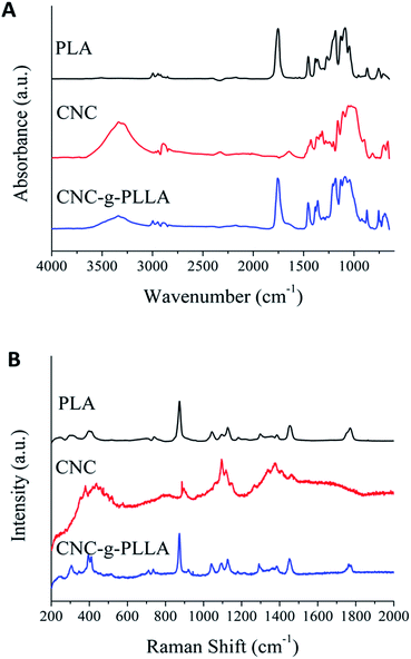
In order to ensure the presence of the PLLA chain in the cellulose nanocrystals surface, vibrational spectroscopy was used. Fig. 2A shows the FTIR spectrum of PLA, CNC and CNC-g-PLLA.The main difference between the spectra for the neat and grafted CNC is the presence of the peak at 1753 cm−1, which corresponds to the stretching frequency of the carbonyl group in PLA and/or lactic acid oligomers.43 Moreover, the FTIR spectra of the CNC and the CNC-g-PLLA show a characteristic broad band in the region from 3000 cm−1 to 3600 cm−1, which corresponds to the hydroxyl group present in the original cellulose structure. Moreover, the Raman spectrum (Fig. 2B) of CNC-g-PLLA shows the characteristic bands of PLA and CNC. These results confirm the success of the grafting procedure.
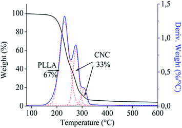
To determine the amount of CNC and PLLA in CNC-g-PLLA, TGA was carried out. The weight loss and the derivative of weight loss are shown in Fig. 3. Three overlapped peaks are observed, in which two of them correspond to the thermal degradation of CNC and the other to the thermal degradation of the PLLA chains. In particular, the CNC peaks present a maximum corresponding to 275 °C, whereas PLLA shows the maximum peak at 230 °C.
CNC present a more broad degradation, as a consequence of the different decomposition mechanism due to the direct solid-to-gas phase transitions catalysed by the sulphate groups on their surface, as reported in the literature.38 The amount of components were computed by fitting the curves with two Gaussian curves, which resulted in the amount of PLLA grafted chains of 67 wt% and the amount of CNC of 33 wt%. The CNC peaks present a maximum corresponding to 275 °C, whereas PLLA shows the maximum peak at 230 °C.
As is well known, cellulose is hydrophilic, hence the dispersion of cellulose in organic solvents is poor.23 In the Molau test, three different solutions were prepared. One of them was a mixture of CNC and PLA dissolved in DMF (vial 1), the second solution was CNC dissolved in DMF (vial 2) and finally CNC-g-PLLA was dissolved DMF (vial 3), using the same concentrations used to prepare the nanocomposites. Fig. 4A shows the image of the solutions taken just after stopping the stirring process. In Fig. 4B, the images were taken after standing for 48 hours. It can be observed that the CNC of both neat CNC and the mixture of CNC and PLA solutions precipitated. However, the suspension of functionalized CNC in the CNC-g-PLLA solution remains stable, as a consequence of the excellent functionalization.
 | ||
| Fig. 4 Molau test results of a mixture of CNC and PLA (vial 1), CNC (vial 2) and CNC-g-PLLA (vial 3) in DMF. | ||
Cellulose nanocrystals suspension characterization
To prepare nanocomposite melt-spun fibers, it is important to obtain well-dispersed nanoparticles in the polymeric matrix because small aggregations of the nano-reinforcements can cause spin failure. On the other hand, the surface modification of CNC is carried out to increase the compatibility between CNC and hydrophobic polymers in order to achieve good dispersion in non-polar solvents, thus making dispersion in biopolymers, such as PLA, easier. For this reason, a study on the dispersion of neat and grafted CNC in different suspensions of DMF and 1,4-dioxane was conducted before the nanocomposite fiber melt-spinning process. The study of birefringence gives an indication of the degree of association or isolation of CNC in a suspension. Therefore, the dispersion of nanoparticles in DMF, as well as in dissolved PLA, was studied using birefringence. Fig. 5A and B show suspensions of CNC and CNC-g-PLLA in DMF, respectively. Fig. 5C shows the dissolved PLA in 1,4-dioxane, and Fig. 5D and E show the suspension of CNC and CNC-g-PLLA in DMF mixed with the dissolved PLA in 1,4-dioxane. Both suspensions of CNC and CNC-g-PLLA showed birefringence, which indicates the good dispersion of CNC in DMF without agglomeration. In the same way, the suspensions of CNC and CNC-g-PLLA mixed with the PLA solution show clear flow birefringence, which was not observed in the case of the PLA solution, thus indicating that the dispersion is good.Melt-spun fibers of PLA and its PLA/CNC nanocomposite
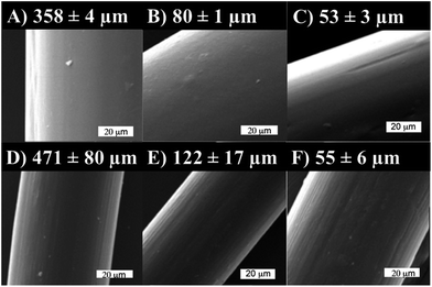
The surface morphology of the melt spun fibers was studied by SEM and the PLA, PLA/CNC and PLA/CNC-g-PLLA melt-spun fibers collected using different speeds are shown in Fig. 6. A continuous and homogeneous surface is observed for every fiber, as well as uniform diameters.
Moreover, the SEM images do not reveal the presence of nanoparticle agglomerates along the fibers surface, which is evidence of well-dispersed cellulose nanocrystals in the PLA matrix.40,41 However, it can be seen from the SEM images that the increase in the collecting speed slightly increased the roughness along the fibers. Cryo-fractured cross-sections of the fibers are shown in Fig. 7. PLA reinforced with CNC and PLA reinforced with CNC-g-PLLA were homogenous and agglomerates of nanoparticles were not observed, which indicate the good dispersion of cellulose nanocrystals in the PLA matrix.
Fig. 8A shows the results of the weight loss and Fig. 8B the derivative of weight loss. The as-spun fibers present thermal stability up to 300 °C.
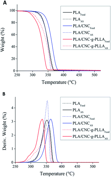 | ||
| Fig. 8 Thermogravimetric analysis of the feed materials and as-spun fibers: (A) weight loss profiles and (B) normalized derivative of weight loss. | ||
In addition, in the case of raw PLA and PLA reinforced with cellulose nanocrystals grafted with PLA, the as-spun fibers show higher thermal stability than the feed materials. Moreover, the addition of nanocrystals increased the thermal stability of the nanocomposites, because of the higher thermal stability of the nanoparticles compared to PLA.
Molecular weight characterization was carried out by GPC in order to study the influence of temperature reached in the compounder on the possible changes on the polymer molecular weight, as a consequence of chain-scission. The PLA molecular weight was evaluated in comparison to the feed material (PLAFeed) with as-spun fibers (PLAAS) and fibers collected using the highest collection speed (PLAMDR2), which is shown in Fig. 9. Both the molecular weight and the distribution of molecular weight remain constant after the melt-spinning process, hence it is possible to conclude that the temperature used in the compounder does not affect the thermal stability of the materials.
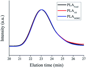 | ||
| Fig. 9 GPC of the feed PLA, PLA fiber after spinning (PLAAS) and PLA after spinning at the highest speed (PLAMDR2). | ||
Furthermore, the crystallinity of the melt-spun fibers can be strongly influenced by the processing conditions such as melt-draw ratio. In this regard, WAXD and thermal analyses were performed.
The WAXD results are reported in Fig. 10A for PLLA, CNC and CNC-g-PLLA. Functionalized CNC show diffraction peaks corresponding to both PLLA and CNC. Moreover, the WAXD results are reported in Fig. 10B for the PLAMDR1, PLA/CNCMDR1 and PLA/CNC-g-PLLAMDR1 melt-spun fibers. The peak intensity corresponding to PLA crystals (Fig. 10B) became stronger when nanoparticles were added, which confirms that the crystallization process was favoured in the nanocomposite fibers.
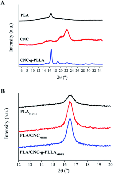 | ||
| Fig. 10 WAXD measurements of (A) PLA, CNC and CNC-g-PLLA and (B) PLAMDR1, PLA/CNCMDR1 and PLA/CNC-g-PLLAMDR1 melt-spun fibers. | ||
Fig. 11 shows DSC thermograms corresponding to the first and second heating scan of the melt-spun fibers of raw PLA (Fig. 11A), PLA reinforced with CNC (Fig. 11B) and PLA reinforced with CNC-g-PLLA (Fig. 11C) compared to fibers collected using different speeds.
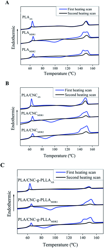 | ||
| Fig. 11 Comparative DSC first and second heating scan curves of feed material and spun fibers collected using different speeds of (A) PLA, (B) PLA/CNC and (C) PLA/CNC-g-PLLA. | ||
The experimental results are reported in Table 2. The degree of crystallinity determined from the first heating scan increases with an increase in the melt-draw ratio, and as a consequence, molecular orientation also increases by increasing the MDR. On the other hand, the degree of crystallinity increases with the addition of CNC-g-PLLA when a higher collection speed is used, hence the influence of nanoparticles on the degree of crystallinity is more important when the melt-draw ratio is high. This fact can be explained by taking into account the fact that cellulose nanocrystals are heterogeneous nucleation sites that favour the start of crystal growth.
| Materials | Tg (°C) | Tc (°C) | Tm (°C) | Xc (%) |
|---|---|---|---|---|
| PLAAS | 63 | 127 | 150 | 0.2 |
| PLAMDR1 | 64 | 100 | 151 | 8.8 |
| PLAMDR2 | 64 | 107 | 145 | 11.3 |
| PLA/CNCAS | 62 | 123 | 149 | 5.8 |
| PLA/CNCMDR1 | 64 | 95 | 151 | 3.7 |
| PLA/CNCMDR2 | 64 | 85 | 151 | 14.4 |
| PLA/CNC-g-PLLAAS | 62 | 124 | 149 | 1.3 |
| PLA/CNC-g-PLLAMDR1 | 64 | 93 | 152 | 7.1 |
| PLA/CNC-g-PLLAMDR2 | 64 | 84 | 151 | 15.0 |
In addition, nanocrystals produce a crystalline slide in the fibers surface called a “transcrystalline slide”.44 Moreover, in the case of the nanocomposites, the cold crystallization temperature is lower than the temperature presented for the raw PLA.
Finally, the crystallization temperature decreases with an increase in MDR.
Even though the first heating scan is representative to study the thermal properties of the fibers, the fiber structure disappears after this scan, and in this case, the second heating scan provides information about the chain orientations. The alignment of chains provides a residual high order, which appears as crystallinity in the second heating.
| Materials | Tensile modulus (MPa) | Tensile strength (MPa) | Elongation at break (%) |
|---|---|---|---|
| PLAAS | 1759 ± 119 | 53.5 ± 2.8 | 26.3 ± 12.5 |
| PLAMDR1-A | 1652 ± 636 | 66.4 ± 2.3 | 47.7 ± 4.1 |
| PLAMDR1 | 2823 ± 130 | 77.8 ± 5.6 | 59.0 ± 7.8 |
| PLAMDR2-A | 3091 ± 235 | 50.9 ± 4.2 | 4.9 ± 1.2 |
| PLAMDR2 | 3455 ± 158 | 82.2 ± 6.6 | 5.0 ± 1.1 |
| PLA/CNCAS | 1918 ± 184 | 53.5 ± 0.9 | 21.3 ± 7.7 |
| PLA/CNCMDR1-A | 1805 ± 369 | 58.8 ± 8.9 | 46.8 ± 4.4 |
| PLA/CNCMDR1 | 2943 ± 368 | 74.8 ± 7.7 | 60.9 ± 11.3 |
| PLA/CNCMDR2-A | 3232 ± 764 | 51.6 ± 12.2 | 24.8 ± 4.2 |
| PLA/CNCMDR2 | 3852 ± 241 | 118.5 ± 16.5 | 51.1 ± 11.3 |
| PLA/CNC-g-PLLAAS | 2265 ± 366 | 51.2 ± 9.0 | 18.1 ± 6.9 |
| PLA/CNC-g-PLLAMDR1-A | 2171 ± 101 | 47.2 ± 0.3 | 25.0 ± 11.5 |
| PLA/CNC-g-PLLAMDR1 | 2973 ± 214 | 65.8 ± 9.3 | 41.9 ± 3.2 |
| PLA/CNC-g-PLLAMDR2-A | 3734 ± 382 | 74.0 ± 10.0 | 4.0 ± 0.5 |
| PLA/CNC-g-PLLAMDR2 | 4125 ± 440 | 171.0 ± 12.6 | 91.7 ± 12.2 |
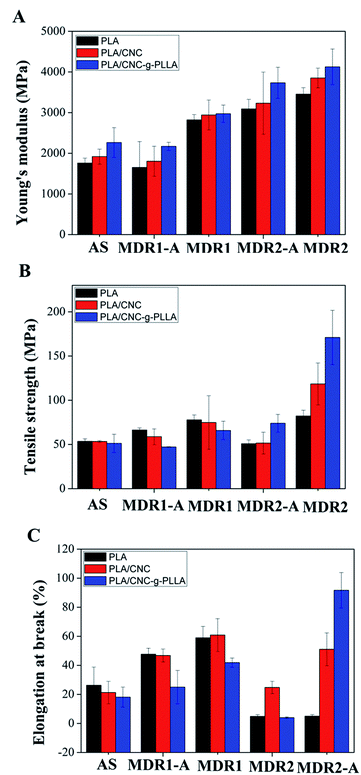 | ||
| Fig. 12 The effect of 1 wt% CNC, modified CNC and draw ratios on (A) tensile modulus; (B) strength and (C) elongation at break. | ||
Fig. 12 summarizes the tensile modulus increase with the addition of both CNC and CNC-g-PLLA to the PLA matrix, as well as by increasing the draw ratio. The same trend was detected for the tensile strength (Fig. 12B) and for the elongation at break (Fig. 12C).
Conclusions
Nanocomposite melt spun fibers based on poly(lactic acid) and cellulose nanocrystals at 1 wt% (PLA/CNC) were prepared in two steps. First, neat PLA and nanocomposites microspheres were obtained using the solvent evaporation method, starting from a DMF-PLA solution, based on thermally induced phase separation. The prepared microspheres were spun into fibers using a micro twin-screw extrusion with a fiber drawing facility. Furthermore, the CNC were successfully grafted with PLLA with the aim to improve the dispersion of the CNC and to create a good interface between the CNC and PLA. FTIR and Raman spectroscopy, as well as TGA analysis and the Molau test, confirmed the success of the grafting reaction. The presence of flow bi confirmed the good dispersion of CNC in the DMF–PLA solutions. It was also shown that the melt-spun nanocomposites fibers did not degrade during the melt spinning process, since the GPC results did not show differences in the molecular weight or molecular weight distribution of the spun fibers compared with the starting material. The addition of cellulose nanocrystals was shown to increase the thermal stability of the nanocomposites, which presented a higher influence on the degree of crystallinity than the melt-draw ratio. Finally, the mechanical properties of the PLA nanocomposite fibers were significantly improved with addition of only 1 wt% CNC, with and without modification. The reinforcing mechanism is the alignment of the CNC and of PLA chains, in which we have earlier shown that such low amount of CNC alone cannot cause a such large increase, but if the CNC together with the polymer is oriented, the orientation very effectively reinforces the fibers. However, the PLLA grafted nanocrystals (CNC-g-PLLA) resulted in increased strain and toughness. These results confirmed better interfacial adhesion between CNC-g-PLLA and the PLA matrix, which indicates that grafting positively affects the properties by acting as a flexible interface between the nanocellulose and PLA thus leading to a higher degree of alignment of the CNC and polymer molecular chains. Furthermore, the dissolving process of PLA was successful to create a good dispersion but needs to be replaced with compounding extrusion in order to produce these fibers on a larger scale.Acknowledgements
We are intended to the Spanish Ministry of Economy and Competitiveness (MAT2013-48059-C2-1 R and MAT2014-55778-REDT) and to the Regional Government of Madrid (S2013/MIT-2862) for their economic support. LP also acknowledges the support of MINECO for the “Ramon y Cajal” contract. The authors gratefully acknowledge the support of LLP/ERASMUS Placement (TUCEP) scholarship for research visit at Luleå University of Technology. Authors are also grateful for Bio4Energy, Swedish strategic research program for the financial support.Notes and references
- L. Peponi, D. Puglia, L. Torre, L. Valentini and J. M. Kenny, Mater. Sci. Eng., R, 2014, 85, 1–46 CrossRef.
- V. J. Chen and P. X. Ma, Biomaterials, 2004, 25, 2065–2073 CrossRef CAS PubMed.
- M. Persson, G. S. Lorite, S. W. Cho, J. Tuukkanen and M. Skrifvars, ACS Appl. Mater. Interfaces, 2013, 5, 6864–6872 CAS.
- M. Persson, S.-W. Cho and M. Skrifvars, J. Mater. Sci., 2013, 48, 3055–3066 CrossRef CAS.
- A. L. Goffin, J. M. Raquez, E. Duquesne, G. Siqueira, Y. Habibi, A. Dufresne and P. Dubois, Biomacromolecules, 2011, 12, 2456–2465 CrossRef CAS PubMed.
- L. Peponi, A. Mujica-Garcia and J. M. Kenny, Poly(lactic acid) Science and Technology: Processing, Properties, Additives and Applications, 2015, p. 171 Search PubMed.
- L. Fambri, A. Pegoretti, R. Fenner, S. D. Incardona and C. Migliaresi, Polymer, 1997, 38, 79–85 CrossRef CAS.
- X. Yuan, A. F. T. Mak, K. W. Kwok, B. K. O. Yung and K. Yao, J. Appl. Polym. Sci., 2001, 81, 251–260 CrossRef CAS.
- L. Peponi, I. Navarro-Baena, J. E. Báez, J. M. Kenny and A. Marcos-Fernández, Polymer, 2012, 53, 4561–4568 CrossRef CAS.
- R. M. Rasal, A. V. Janorkar and D. E. Hirt, Prog. Polym. Sci., 2010, 35, 338–356 CrossRef CAS.
- R. Auras, B. Harte and S. Selke, Macromol. Biosci., 2004, 4, 835–864 CrossRef CAS PubMed.
- P. Bordes, E. Pollet and L. Avérous, Prog. Polym. Sci., 2009, 34, 125–155 CrossRef CAS.
- M. Darder, P. Aranda and E. Ruiz-Hitzky, Adv. Mater., 2007, 19, 1309–1319 CrossRef CAS.
- A. Sorrentino, G. Gorrasi and V. Vittoria, Trends Food Sci. Technol., 2007, 18, 84–95 CrossRef CAS.
- Y. Habibi, L. A. Lucia and O. J. Rojas, Chem. Rev., 2010, 110, 3479–3500 CrossRef CAS PubMed.
- D. Bondeson and K. Oksman, Composites, Part A, 2007, 38, 2486–2492 CrossRef.
- L. Petersson, I. Kvien and K. Oksman, Compos. Sci. Technol., 2007, 67, 2535–2544 CrossRef CAS.
- D. Bondeson and K. Oksman, Compos. Interfaces, 2007, 14, 617–630 CrossRef CAS.
- K. Oksman, A. P. Mathew, D. Bondeson and I. Kvien, Compos. Sci. Technol., 2006, 66, 2776–2784 CrossRef CAS.
- L. Petersson and K. Oksman, Compos. Sci. Technol., 2006, 66, 2187–2196 CrossRef CAS.
- M. P. Arrieta, E. Fortunati, F. Dominici, E. Rayon, J. Lopez and J. M. Kenny, Carbohydr. Polym., 2014, 107, 16–24 CrossRef CAS PubMed.
- A. Carlmark, E. Larsson and E. Malmström, Eur. Polym. J., 2012, 48, 1646–1659 CrossRef CAS.
- I. Navarro-Baena, J. M. Kenny and L. Peponi, Cellulose, 2014, 21, 4231–4246 CrossRef CAS.
- M. S. Kim, J. C. Kim and Y. H. Kim, Polym. Adv. Technol., 2008, 19, 748–755 CrossRef CAS.
- Y. Furuhashi, Y. Kimura and H. Yamane, J. Polym. Sci., Part B: Polym. Phys., 2007, 45, 218–228 CrossRef CAS.
- Y. Nishimura, A. Takasu, Y. Inai and T. Hirabayashi, J. Appl. Polym. Sci., 2005, 97, 2118–2124 CrossRef CAS.
- B. Gupta, N. Revagade, N. Anjum, B. Atthoff and J. Hilborn, J. Appl. Polym. Sci., 2006, 100, 1239–1246 CrossRef CAS.
- B. Gupta, N. Revagade, N. Anjum, B. Atthoff and J. Hilborn, J. Appl. Polym. Sci., 2006, 101, 3774–3780 CrossRef CAS.
- A. Mujica-Garcia, I. Navarro-Baena, J. M. Kenny and L. Peponi, J. Renewable Mater., 2014, 2, 23–34 CrossRef CAS.
- F. Yang, R. Murugan, S. Wang and S. Ramakrishna, Biomaterials, 2005, 26, 2603–2610 CrossRef CAS PubMed.
- A. Sonseca, L. Peponi, O. Sahuquillo, J. M. Kenny and E. Giménez, Polym. Degrad. Stab., 2012, 97, 2052–2059 CrossRef CAS.
- V. Taubner and R. Shishoo, J. Appl. Polym. Sci., 2001, 79, 2128–2135 CrossRef CAS.
- G. Schmack, B. Tändler, R. Vogel, R. Beyreuther, S. Jacobsen and H. G. Fritz, J. Appl. Polym. Sci., 1999, 73, 2785–2797 CrossRef CAS.
- J. Cicero and J. Dorgan, J. Polym. Environ., 2001, 9, 1–10 CrossRef CAS.
- M. J. John, R. Anandjiwala, K. Oksman and A. P. Mathew, J. Appl. Polym. Sci., 2013, 127, 274–281 CrossRef CAS.
- J. J. Blaker, K.-Y. Lee, M. Walters, M. Drouet and A. Bismarck, React. Funct. Polym., 2014, 85, 185–192 CrossRef CAS.
- E. D. Cranston and D. G. Gray, Biomacromolecules, 2006, 7, 2522–2530 CrossRef CAS PubMed.
- E. Fortunati, I. Armentano, Q. Zhou, A. Iannoni, E. Saino, L. Visai, L. A. Berglund and J. M. Kenny, Carbohydr. Polym., 2012, 87, 1596–1605 CrossRef CAS.
- M. A. S. Azizi Samir, F. Alloin, J.-Y. Sanchez, N. El Kissi and A. Dufresne, Macromolecules, 2004, 37, 1386–1393 CrossRef.
- S. Hooshmand, S.-W. Cho, M. Skrifvars, A. Mathew and K. Oksman, Plast., Rubber Compos., 2014, 43, 15–24 CrossRef CAS.
- S. Hooshmand, Y. Aitomäki, M. Skrifvars, A. P. Mathew and K. Oksman, Cellulose, 2014, 21, 2665–2678 CrossRef CAS.
- N. Naseri, C. Algan, V. Jacobs, M. John, K. Oksman and A. P. Mathew, Carbohydr. Polym., 2014, 109, 7–15 CrossRef CAS PubMed.
- N. Lin, G. Chen, J. Huang, A. Dufresne and P. R. Chang, J. Appl. Polym. Sci., 2009, 113, 3417–3425 CrossRef CAS.
- D. Liu, X. Yuan and D. Bhattacharyya, J. Mater. Sci., 2011, 47, 3159–3165 CrossRef.
| This journal is © The Royal Society of Chemistry 2016 |

