A MOF-derived nickel based N-doped mesoporous carbon catalyst with high catalytic activity for the reduction of nitroarenes†
Wei
Zuo
,
Guiqin
Yu
and
Zhengping
Dong
*
College of Chemistry and Chemical Engineering, Gansu Provincial Engineering Laboratory for Chemical Catalysis, Lanzhou University, Lanzhou 730000, PR China. E-mail: dongzhp@lzu.edu.cn; Fax: +86 0931 8912582; Tel: +86 0931 8912577
First published on 15th January 2016
Abstract
An N-doped mesoporous carbon supported Ni nanoparticle nanocatalyst (Ni/m-CN) was prepared in a facile manner by the carbonization of Ni-MOFs. The Ni/m-CN nanocatalyst exhibited excellent catalytic activity for the reduction of nitroarenes under mild conditions. Moreover, the Ni/m-CN nanocatalyst can also be easily recovered and reused due to its superparamagnetism.
Introduction
The use of noble metals such as Pd, Pt, Ru, Rh, and Au for preparing catalysts has long been a hot topic of research due to their high catalytic activities.1–3 However, because noble metals are scarce and expensive, nowadays, researchers must develop highly active catalysts taking into account cost, catalyst fabrication, and restocking.4 One promising solution is to replace the commonly used noble-metal catalysts with non-noble-metal catalysts.5 In this regard, transition metals such as Co and Ni have recently attracted considerable attention, due to their low cost and excellent catalytic activities for the reduction of oxygen, hydrogenation, as well as production of hydrogen.6–8 For increasing catalytic activities, Co or Ni nanoparticles (NPs) are always highly supported on solid materials to prepare a heterogeneous nanocatalyst. Among the solid supports, such as mesoporous silica as well as alumina and carbon materials,9–11 mesoporous carbonaceous supports have been demonstrated to be the first choice as catalyst supports, caused by their excellent stability and chemical inertness.11 In particular, recently, mesoporous carbon nitride (m-CN) materials, which exhibit excellent physicochemical properties, have been extensively employed for the preparation of heterogeneous catalysts.12 MOFs have recently been used to prepare m-CN materials through carbonization method.13–15 These m-CN materials have amino groups inbuilt on their mesoporous walls, which can serve as condensation centers for the grafting of metal NPs, thereby leading to m-CN-material-based catalysts containing well-dispersed catalytically active sites; these sites in turn will subsequently enhance catalytic activities.16,17 Hence, it is crucial to prepare non-precious metal catalysts, especially Ni-modified m-CN catalysts, for catalyzing organic reactions.On the other hand, in recent years, a significant challenge for green chemistry is to overcome environmental pollution. Using a catalytic process for the disposal of environmental pollutants and transforming harmful organic wastes into useful, reusable industrial chemicals with low toxicity under mild reaction conditions are imperative for chemists.18 Among all hazardous organic wastes listed in the United States Environmental Protection Agency, nitrophenols can undergo catalytic reduction to afford aminophenols as the useful product. This process has often been catalyzed by noble-metal catalysts and been widely reported;19–21 however, the use of non-precious metal catalysts is rare.
Based on the abovementioned considerations, in this study, we describe the fabrication of the Ni/m-CN nanocatalyst with uniformly distributed Ni NPs, derived from Ni-MOFs, in a facile manner. In the catalytic reduction of 4-nitrophenol (4-NP), the Ni/m-CN nanocatalyst exhibited excellent catalytic activity along with easy recovery and reusability.
Experimental
Chemicals
Ni(NO3)2·6H2O, 4,4′-bipyridine (4,4′-bipy), and 1,3,5-benzenetricarboxylic acid (H3BTC) were purchased from Sigma-Aldrich. Reagent-grade 4-NP was purchased from Aladdin Reagents. All other analytical grade reagents and solvents were used as received.Fabrication of Ni-MOFs
Ni-MOFs were prepared according to a previously reported route.22,23 Typically, 4,4′-bipy (0.576 g, 3 mmol), H3BTC (0.633 g, 3 mmol), and Ni(NO3)2·6H2O (0.876 g, 3 mmol) were dissolved in DMF (60 mL) under vigorous stirring at room temperature for 10 min. Then, the green colored transparent solution was transferred to a Teflon-lined autoclave and maintained at 80 °C for 3 days. After cooling to 20 °C, the green crystal-like solid was obtained by filtration and thoroughly washed with DMF. Finally, the Ni-MOFs materials obtained were dried overnight at 60 °C in a vacuum oven (1.267 g). According to the reported work, the formula of the obtained Ni-MOFs was [Ni(HBTC)(4,4′-bipy)]·3DMF.23 Thus the yield of the Ni-MOFs was 65.8%.Preparation of Ni/m-CN
The dry powder of Ni-MOFs (3 g) was calcined up to 700 °C under inert atmosphere at a heating rate of 5 °C min−1 in a tube furnace and maintained at 700 °C for 2 h. Then, the resulting nanocomposites were cooled to room temperature, affording 0.65 g of Ni/m-CN nanocatalyst, 21.7% yield of the Ni-MOFs.Evaluation of catalytic activities
For evaluating the catalytic activity, the Ni/m-CN nanocatalyst was tested by the catalytic reduction of 4-NP by NaBH4 as the probe reaction. First, the aqueous solution of 4-NP (0.01 M, 30 μL) was mixed with H2O (2.3 mL), and then the freshly prepared NaBH4 aqueous solution (0.5 M, 0.15 mL) was added, subsequently affording a deep yellow solution. Then, the Ni/m-CN aqueous dispersion (0.5 mL, 2 mg mL−1) was added to the reaction mixture, and the reaction was started and continued until the solution became colorless. The reaction was monitored by the measurement of UV-vis absorption spectra. After reduction, the Ni/m-CN nanocatalyst was recovered using an external magnetic field for the next catalytic run.Characterization
The morphology of the samples was observed by scanning electron microscopy (SEM, JSM-6701F) and transmission electron microscopy (TEM, Tecnai G2F30) with energy-dispersive spectroscopy (EDS). Powder X-ray diffraction (PXRD, Rigaku D/max-2400) measurement was carried out on a diffractometer using Cu-Kα radiation as the X-ray source in the 2θ range of 10–85°. Raman spectroscopy (Jobin-Yvon LabRam HR evolution) was also employed for the characterization of the Ni/m-CN nanocatalyst. X-ray photoelectron spectroscopy (XPS, PHI-5702) was employed for the analysis of the electronic states of the surface of the Ni/m-CN nanocatalyst using the C 1s line at 284.6 eV as the binding energy reference. The magnetic measurement of the Ni/m-CN nanocatalyst was investigated by a vibrating sample magnetometer at room temperature in an applied magnetic field sweeping from −20 to 20 kOe. Nitrogen adsorption–desorption experiments were performed at 77 K using a Micromeritics ASAP 2010 analyzer (USA). Inductively coupled plasma atomic emission spectroscopy (ICP-AES) and elemental analysis (GmbH Vario El Elementar) were also employed to measure the Ni, N, C, and H contents of the Ni/m-CN nanocatalyst. The reaction progress was measured using a Shimadzu UV 2100 PC UV-visible spectrometer.Results and discussion
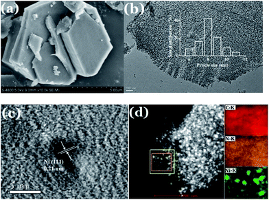
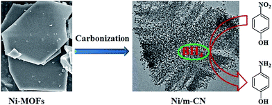
In this study, the Ni-MOFs were easily prepared using 4,4′-bipy, H3BTC, and Ni(NO3)2·6H2O as precursors. As reported in Prof. Kitagawa's work, the Ni(0)@MOFs could be formed by partial thermal decomposition of Ni(II)-MOFs.24 Thus, in the current work, the Ni-MOFs were calcined under nitrogen at 700 °C, then they were converted to the magnetic Ni/m-CN nanocatalyst, with metallic Ni NPs embedded in the m-CN framework.Fig. 1 shows the morphology of Ni-MOFs and Ni/m-CN. As shown in Fig. 1a, plates of Ni-MOFs with a side length of approximately 5 μm and thickness of 1–2 μm were observed. After calcination under inert atmosphere, the blue powder (Fig. S1a†) Ni-MOFs were converted to black powder (Fig. S1b†), with Ni NPs embedded in the framework (Fig. 1b). The Ni NPs were generated during calcination because of the reducibility of the C framework. As shown in Fig. 1b, the mean particle size of the Ni NPs measured from the TEM image was about 8 nm, which is in agreement with predictions by the Scherrer equation. Moreover, the Ni NPs were not aggregated. The measured lattice fringe spacing of the Ni NPs was 0.21 nm, revealing the crystal plane distances of the nickel (1 1 1) plane (Fig. 1c). Fig. 1d shows the high-angle annular dark field scanning transmission electron microscopy results, which confirm the elemental distribution of the Ni/m-CN nanocatalyst. The same results were observed as those obtained from EDS (Fig. S2†). The support was clearly composed mainly of C and N elements. The catalytic activity center (Ni NPs) was well dispersed in the mesopores of m-CN.
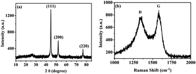
Fig. 2a shows the XRD pattern of the Ni/m-CN nanocatalyst. A broad characteristic peak was observed at around 24.3°, attributed to the (0 0 2) plane of carbon materials that are generated during the carbonization of Ni-MOFs. During carbonization, all the high-valence nickel in the Ni/m-CN nanocatalyst was reduced to metallic Ni NPs with good crystallinity. Thus, the intensive diffraction peaks at 44.6°, 52°, and 76.6° are associated with the (1 1 1), (2 0 0), and (2 2 0) planes of the face-centered-cubic (fcc) structure Ni (JCPDS no. 04-0850), respectively.11Fig. 2b shows the Raman spectrum of the Ni/m-CN nanocatalyst: two bands were observed at 1370 and 1580 cm−1, which are indexed as the disordered (D) and graphitic (G) modes of carbon, respectively. The relative ID/IG value for the Ni/m-CN nanocatalyst was 0.88, confirming that the m-CN support has comparatively high C(sp2)-hybridized content; this result confirms the highly graphitized structures of the catalyst.25
XPS spectroscopy was employed for studying the electronic states of the Ni/m-CN nanocatalyst. Fig. 3a shows the global XPS spectrum; the Ni/m-CN nanocatalyst was mainly composed of carbon, nitrogen, and nickel. The C 1s = 284.6 eV was used as the reference (Fig. 3b), and the N 1s spectrum (Fig. 3c) was curve-fitted into two peaks with binding energies of 398.8 and 400.8 eV, attributed to pyridinic N and pyrrolic N, respectively.17 In Fig. 3d, a peak was observed at 852.9 eV, in addition to a satellite peak at 859.8 eV, attributed to the Ni 2p3/2 levels. Besides, another peak was observed at 870.8 eV, attributed to the Ni 2p1/2 level.26 As the binding energy of Ni(II) (Ni 2p3/2, 856.1 eV)24 does not appear in the XPS spectrum, it can be confirmed that the Ni(II) in the Ni-MOFs almost completely converted to metallic Ni NPs and embedded in the m-CN framework.
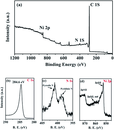 | ||
| Fig. 3 (a) XPS spectrum of Ni/m-CN nanocatalyst, (b) C 1s, (c) N 1s and (d) Ni 2p XPS spectra of Ni/m-CN nanocatalyst. | ||
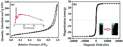
Fig. 4a shows the N2 sorption isotherm of the Ni/m-CN nanocatalyst, which confirms the porosity of the mesoporous Ni/m-CN nanocatalyst.27 The BET surface area calculated for the Ni/m-CN nanocatalyst was 134 m2 g−1. The pore size derived from the adsorption branch exhibited the wide distribution of large mesopore size between 4 and 50 nm (Fig. 4a inset), and the mean pore size was 10.8 nm (Table S1†). The high surface area and large mesopore size are beneficial for mass transfer during catalytic reactions. Besides, from elemental analysis, the N content was 1.54% (Table S1†). As obtained from ICP-AES measurement, the weight percentage of Ni NPs in the Ni/m-CN nanocatalyst was approximately 48.3 wt% (Table S1†), implying a rich Ni content in the Ni/m-CN nanocatalyst. As shown in Fig. 4b, the saturation magnetization of the Ni/m-CN nanocatalyst was 26.8 emu g−1, which is mainly caused by the ferromagnetic property of the Ni NPs. Thus, the Ni/m-CN nanocatalyst is efficiently recovered from the reaction solution by an external magnet and reused (Fig. 4b, inset) in the subsequent catalytic runs.28
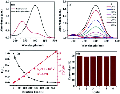
The catalytic reduction of 4-NP is well known to be one of the model reactions for appraising the catalytic activity of the nanocatalyst.29 Thus, we investigated the catalytic activity of the Ni/m-CN nanocatalyst by employing the reduction of 4-NP to 4-AP. As is well known, because the difference in the standard electrode potentials is greater than zero (ΔE0 = E0(4-NP/4-AP) −  = −0.76 − (−1.33) = 0.67 V),30 the reduction of 4-NP by NaBH4 is thermodynamically favorable. However, in the absence of an efficient catalyst, this reaction was kinetically restricted.31 As shown in Fig. 5a, the absorption peak of 4-NP solutions was observed at 317 nm under non-alkaline conditions. By the addition of NaBH4, the absorption peak originally at 317 nm shifted to 400 nm, attributed to the formation of 4-nitrophenolate ions under highly basic conditions, and the solution also changed from light yellow to bright yellow (Fig. S3†).32 Furthermore, the maximum absorption at 400 nm did not change over time, confirming that NaBH4 cannot reduce 4-NP. When 1 mg of the Ni/m-CN nanocatalyst was added to the reaction mixture, the peak intensity of 4-nitrophenolateion at 400 nm decreased with a company increase in the peaks corresponding to 4-AP at 300 nm. The reaction rapidly proceeded with the conversion of 4-NP exceeding 99% at a reaction time of approximately 10 min (Fig. 5b). After the reaction was completed, the reaction mixture became colorless. Scheme 1 shows the catalytic performance of the Ni/m-CN nanocatalyst, and the catalytic reduction of 4-NP to 4-AP using NaBH4 can be explained as follows: when 4-NP and BH4− ions were adsorbed on the Ni NPs, reduction occurred by the relay of electrons from the donor BH4− to the acceptor 4-NP.21,33
Because the initial concentration of the NaBH4 solution is significantly higher than that of 4-NP, it can be considered as a constant throughout the reduction of 4-NP. Thus, the reduction rate is assumed to be independent of the NaBH4 concentration, in which case, reduction can be considered as a pseudo-first-order reaction.34 Hence, pseudo-first-order kinetics can be applied for the evaluation of the kinetic rate constant (k) of reduction [eqn (1)], where A0 and At represent the absorbance values of 4-NP at the start and at time t, respectively.
| ln(Ct/C0) = ln(At/A0) = −kt | (1) |
As shown in Fig. 5c, as expected, a linear relationship was observed between ln(Ct/C0) and the reaction time t, as confirmed by pseudo-first-order kinetics. The corresponding pseudo-first-order rate constant k was 9.1 × 10⁻³ s−1. For comparing the catalytic activities of different catalysts, the ratio of the rate constant k over the total weight of the catalyst was calculated, where k′ = k/m. The activity factor k′ for the Ni/m-CN nanocatalyst was calculated to be 9.1 s−1 g−1, which is approximately the same as those for the Ag-doped carbon sphere catalyst (1.69 s−1 g−1) and the Fe3O4@SiO2–Ag catalyst (7.67 s−1 g−1).35,36 Compared with other Ni based catalyst (p(AMPS)-Ni, 0.019 s−1 g−1)37 and Co based catalyst (p(AMPS)-Co, 0.04 s−1 g−1),38 the Ni/m-CN also has higher catalytic performance. The excellent catalytic activity of the Ni/m-CN nanocatalyst was attributed to its highly dispersed Ni NPs with easy accessibility in the mesopores of m-CN, thereby resulting in the rapid occurrence and completion of reduction.
To evaluate recyclability, the Ni/m-CN nanocatalyst was separated from the reaction medium using a magnet and was reused in five further cycles. The catalytic performance of the Ni/m-CN nanocatalyst was preserved in terms of reaction time and 4-NP conversion, without any loss of efficiency after six cycles, indicating its excellent catalytic activity and stability upon reuse (Fig. 5d). After six consecutive cycles, the magnetic nanocatalysts were further characterized by transmission electron microscopy (Fig. S4†): the morphology of the Ni/m-CN nanocatalyst used for six cycles was almost maintained. This result suggests that the Ni/m-CN nanocatalyst possesses robust stability.
Conclusions
The Ni/m-CN nanocatalyst derived from Ni-MOFs was used for the catalytic reduction of 4-NP under mild reaction conditions. The nanocatalyst exhibited excellent catalytic activity and could also be easily recycled and reused. This study may promote the study of the design of catalyst materials derived from various MOFs with non-precious metals and efficient, convenient magnetic recovery.Acknowledgements
The authors acknowledge financial support from the Fundamental Research Funds for the Central Universities (lzujbky-2015-21 and lzujbky-2015-32).Notes and references
- J. Y. Hu, Q. W. Yang, L. F. Yang, Z. G. Zhang, B. G. Su, Z. B. Bao, Q. L. Ren, H. B. Xing and S. Dai, ACS Catal., 2015, 5, 6724–6731 CrossRef CAS.
- L. Yuwen, F. Xu, B. Xue, Z. Luo, Q. Zhang, B. Bao, S. Su, L. Weng, W. Huang and L. Wang, Nanoscale, 2014, 6, 5762–5769 RSC.
- J. Zhang, S. Lu, Y. Xiang, P. K. Shen, J. Liu and S. P. Jiang, ChemSusChem, 2015, 8, 2956–2966 CrossRef CAS PubMed.
- M. Kokate, S. Dapurkar, K. Garadkar and A. Gole, J. Phys. Chem. C, 2015, 119, 14214–14223 CAS.
- C. J. Jiang, Z. Y. Shang and X. H. Liang, ACS Catal., 2015, 5, 4814–4818 CrossRef CAS.
- M. B. Gawande, H. Guo, A. K. Rathi, P. S. Branco, Y. Chen, R. S. Varma and D.-L. Peng, RSC Adv., 2013, 3, 1050–1054 RSC.
- M. Kim, D.-H. Nam, H.-Y. Park, C. Kwon, K. Eom, S. Yoo, J. Jang, H.-J. Kim, E. Cho and H. Kwon, J. Mater. Chem. A, 2015, 3, 14284–14290 CAS.
- Y.-R. Zheng, M.-R. Gao, Z.-Y. Yu, Q. Gao, H.-L. Gao and S.-H. Yu, Chem. Sci., 2015, 6, 4594–4598 RSC.
- J. Sun, X. D. Jin, F. W. Zhang, W. Q. Hu, J. T. Liu and R. Li, Catal. Commun., 2012, 24, 30–33 CrossRef CAS.
- N. Yan, Z. Zhao, Y. Li, F. Wang, H. Zhong and Q. Chen, Inorg. Chem., 2014, 53, 9073–9079 CrossRef CAS PubMed.
- Y. Yang, Y. Ren, C. Sun and S. Hao, Green Chem., 2014, 16, 2273–2280 RSC.
- Z. Zhao, Y. Dai, J. Lin and G. Wang, Chem. Mater., 2014, 26, 3151–3161 CrossRef CAS.
- N. L. Torad, M. Hu, S. Ishihara, H. Sukegawa, A. A. Belik, M. Imura, K. Ariga, Y. Sakka and Y. Yamauchi, Small, 2014, 10, 2096–2107 CrossRef CAS PubMed.
- N. Sun, X. Zhang and C. Deng, Nanoscale, 2015, 7, 6487–6491 RSC.
- Z. Li and L. Yin, Nanoscale, 2015, 7, 9597–9606 RSC.
- Z. Dong, C. Dong, Y. Liu, X. Le, Z. Jin and J. Ma, Chem. Eng. J., 2015, 270, 215–222 CrossRef CAS.
- J. Xu, T. Chen, Q. Jiang and Y. X. Li, Chem.–Asian J., 2014, 9, 3269–3277 CrossRef CAS PubMed.
- I. Ibrahim, I. O. Ali, T. M. Salama, A. A. Bahgat and M. M. Mohamed, Appl. Catal., B, 2016, 181, 389–402 CrossRef CAS.
- Z. Jiang, D. Jiang, A. M. Showkot Hossain, K. Qian and J. Xie, Phys. Chem. Chem. Phys., 2015, 17, 2550–2559 RSC.
- Y.-Y. Shen, Y. Sun, L.-N. Zhou, Y.-J. Li and E. S. Yeung, J. Mater. Chem. A, 2014, 2, 2977–2984 CAS.
- S. Dutta, S. Sarkar, C. Ray, A. Roy, R. Sahoo and T. Pal, ACS Appl. Mater. Interfaces, 2014, 6, 9134–9143 CAS.
- X. Hu, Z. Zhu, F. Cheng, Z. Tao and J. Chen, Nanoscale, 2015, 7, 11833–11840 RSC.
- Y. Li, L. Xie, Y. Liu, R. Yang and X. Li, Inorg. Chem., 2008, 47, 10372–10377 CrossRef CAS PubMed.
- M. Mukoyoshi, H. Kobayashi, K. Kusada, M. Hayashi, T. Yamada, M. Maesato, J. M. Taylor, Y. Kubota, K. Kato, M. Takata, T. Yamamoto, S. Matsumura and H. Kitagawa, Chem. Commun., 2015, 51, 12463–12466 RSC.
- W. Xiong, X. Hu, X. Wu, Y. Zeng, B. Wang, G. He and Z. Zhu, J. Mater. Chem. A, 2015, 3, 17209–17216 CAS.
- J. Li, Y. H. Wang, J. Tang, Y. Wang, T. Y. Wang, L. J. Zhang and G. F. Zheng, J. Mater. Chem. A, 2015, 3, 2876–2882 CAS.
- Y. Chen, B. Song, M. Li, L. Lu and J. Xue, Adv. Funct. Mater., 2014, 24, 319–326 CrossRef CAS.
- T. J. Yao, T. Y. Cui, X. Fang, F. Cui and J. Wu, Nanoscale, 2013, 5, 5896–5904 RSC.
- H. Zhang, T. Duan, W. K. Zhu and W. T. Yao, J. Phys. Chem. C, 2015, 119, 21465–21472 CAS.
- B. Baruah, G. J. Gabriel, M. J. Akbashev and M. E. Booher, Langmuir, 2013, 29, 4225–4234 CrossRef CAS PubMed.
- S. Fountoulaki, V. Daikopoulou, P. L. Gkizis, I. Tamiolakis, G. S. Armatas and I. N. Lykakis, ACS Catal., 2014, 4, 3504–3511 CrossRef CAS.
- Q. Wang, W. Jia, B. Liu, A. Dong, X. Gong, C. Li, P. Jing, Y. Li, G. Xu and J. Zhang, J. Mater. Chem. A, 2013, 1, 12732–12741 CAS.
- Z. Wang, H. Fu, D. Han and F. Gu, J. Mater. Chem. A, 2014, 2, 20374–20381 CAS.
- S. Zhang, S. Gai, F. He, Y. Dai, P. Gao, L. Li, Y. Chen and P. Yang, Nanoscale, 2014, 6, 7025–7032 RSC.
- S. Tang, S. Vongehr and X. Meng, J. Phys. Chem. C, 2010, 114, 977–982 CAS.
- Y. Chi, Q. Yuan, Y. Li, J. Tu, L. Zhao, N. Li and X. Li, J. Colloid Interface Sci., 2012, 383, 96–102 CrossRef CAS PubMed.
- N. Sahiner, H. Ozay, O. Ozay and N. Aktas, Appl. Catal., A, 2010, 385, 201–207 CrossRef CAS.
- N. Sahiner, H. Ozay, O. Ozay and N. Aktas, Appl. Catal., B, 2010, 101, 137–143 CrossRef CAS.
Footnote |
| † Electronic supplementary information (ESI) available: Photographs of Ni-MOFs and Ni/m-CN, EDS spectra of Ni/m-CN, the color change of 4-NP solution before and after adding NaBH4, the TEM image of the Ni/m-CN nanocatalyst used after six cycles, and the physiochemical parameters of the Ni/m-CN nanocatalyst can be found in the ESI. See DOI: 10.1039/c5ra23082a |
| This journal is © The Royal Society of Chemistry 2016 |

