
Synergistic effect of polymorphism, substrate conductivity and electric field stimulation towards enhancing muscle cell growth in vitro†
Ravikumar K‡
a,
Goutam Prasanna Kar‡b,
Suryasarathi Bose *b and
Bikramjit Basu*a
*b and
Bikramjit Basu*a
aMaterials Research Centre, Indian Institute of Science, Bangalore, India. E-mail: bikram@mrc.iisc.ernet.in; sbose@materials.iisc.ernet.in
bDepartment of Materials Engineering, Indian Institute of Science, Bangalore, India
First published on 18th January 2016
Abstract
Poly(vinylidene difluoride), a well-known candidate for artificial muscle patch applications is a semi-crystalline polymer with a host of attributes such as piezo- and pyroelectricity, polymorphism along with low dielectric constant and stiffness. The present work explores the unique interplay among the factors (conductivity, polymorphism and electrical stimulation) towards cell proliferation on poly(vinylidene difluoride) (PVDF)-based composites. In this regard, multi-walled carbon nanotubes (MWNTs) are introduced in the PVDF matrix (limited to 2%) through melt mixing to increase the conductivity of PVDF. The addition of MWNTs also led to an increase in the fraction of piezoelectric β-phase, tensile strength and modulus. The melting and crystallization behaviour of PVDF–MWNT together with FT-IR confirms that the crystallization is found to be aided by the presence of MWNT. The conducting PVDF–MWNTs are used as substrates for the growth of C2C12 mouse myoblast cells and electrical stimulation with a range of field strengths (0–2 V cm−1) is intermittently delivered to the cells in culture. The cell viability results suggest that metabolically active cell numbers can statistically increase with electric stimulation up to 1 V cm−1, only on the PVDF + 2% MWNT. Summarising, the current study highlights the importance of biophysical cues on cellular function at the cell–substrate interface. This study further opens up new avenues in designing conducting substrates, that can be utilized for enhancing cell viability and proliferation and also reconfirms the lack of toxicity of MWNTs, when added in a tailored manner.
1. Introduction
Since their discovery, electroactive polymers (EAPs) have found a wide range of applications as transducers, actuators, sensors and information processors in biomedical applications, robotics, microelectronics, energy harvesting, electrostriction and battery technologies.1–8 Recent advances, especially in biomedical research have shown an enormous potential of both conducting and non-conducting EAPs for applications such as artificial muscles, hand and limb prostheses, drug delivery and sensing.9–13 Among the EAPs, poly(vinylidene diflouride) (PVDF) is one of the most versatile and widely studied, mainly due to the impressive combination of piezo- and pyroelectricity combined with excellent chemical stability. However, PVDF is a bioinert material. It is particularly useful for sensors and actuators due to its low dielectric constant and elastic stiffness.14–17 Apart from being used for biosensors and transducers, PVDF is also used in textile industries in designing wearable tactile sensors, as energy harvesting devices, as filtering membranes, as surgical sutures and meshes and as a substrate in protein detection and analyses using western blot assay.PVDF is a semi-crystalline polymer that can crystallise mainly into two distinct phases (α and β) and two less common high temperature phases (γ and δ). Generally, when PVDF is prepared by cooling from the melt, the major phase obtained is α. The α-phase, due to the TGTG′ (T-trans, G-gauche) orientation, is non-polar. The β-phase, on the other hand, crystallises in all-trans (TTTT) orientation making it highly polar and responsible for the piezo and pyroelectric properties of PVDF. Hence, the electroactive properties of PVDF depend largely on the amount of β-phase and naturally, methods to maximise the content of β-phase in PVDF have generated interest in the research community.
The enhancement in the content of β-phase can be achieved by various techniques. Among them, the most commonly used are rolling, uniaxial stretching at high temperature (ca. 85 °C) with a stretch ratio of 3–5, poling at electric fields as high as 1 MV cm−1 and the addition of nanofillers such as CNTs/nanoclay to the PVDF melt, or a combination of these techniques.18–24 The efficiency of conversion to β-phase is usually determined by a variety of characterization techniques such as FT-IR, X-ray diffraction and DSC. The piezoelectric co-efficient is found to increase with the β-phase content in PVDF and a maximum of 60 pC N−1 has been measured in β-phase PVDF films.24
Though the bioinert PVDF with enhanced β-phase shows excellent piezo- and pyroelectric properties, it is a poor conductor of electricity with conductivity values as low as 10−12 S cm−1. It is long since agreed that electroactive substrates can be used effectively to tune the response of various cell types both with and without the influence of external electric fields to obtain enhanced cell growth, shape change, differentiation of stem cells into bone, muscle and neural like cells.25–29 A few outstanding examples of this include studies reporting the control of endothelial cell shape and growth kinetics in the presence of external electric field on conducting polymer substrates such as polypyrrole.25 A similar study on polypyrrole with human Mesenchymal Stem Cells (hMSCs) have also shown that they support osteogenic differentiation in vitro.29 In a different work, enhanced neurite outgrowth of neural cells has been observed on conducting substrates in the presence of electrical stimulus.26 Apart from this, other common EAPs used in conjunction with biological cells and tissues are polythiophene, polyaniline which can exhibit a wide range of conductivities depending on the dopant used (e.g. HCl doping in polyaniline).30,31
Recently, regenerative cell therapies are gaining prominence in the biomedical research field. A number of studies focus on using the ease and flexibility in the preparation of conducting EAPs in various forms to elicit favourable cell responses. For instance, low intensity electric field stimulation of hMSCs on doped polyaniline films were reported to cause differentiation into neural-like cells.27 Similarly, conducting EAPs in other forms such as electrospun nanofibres, nanotube composites and scaffolds have been used to increase nerve cell regeneration and direct stem cell differentiation to a particular lineage.28,32,33
In this context, the present work reports the addition of multiwall carbon nanotubes (MWNTs) to PVDF matrix in order to increase its conductivity. Importantly, the addition of nanofillers (in this case MWNTs) also increases mechanical strength and is reported to act as nucleation centres for the β-phase crystals during processing.21,34 The PVDF–MWNT composites with good conductivity and enhanced piezoelectric properties (β-phase) have been used here as substrates for culturing C2C12 mouse myoblasts cells in the presence of electric field to confirm the field dependent effect on cell functionality. Such studies can have potential applications in electric field induced nerve regeneration, wound healing and stem cell therapies.
2. Materials and methods
2.1 Preparation of PVDF–MWNT composites by melt mixing
PVDF (Kynar-761, with Mw of 440![[thin space (1/6-em)]](https://www.rsc.org/images/entities/char_2009.gif) 000 g mol−1) was procured from Arkema (Colombes, France). MWNTs (NC 7000, average diameter of 9.5 nm and an average length of 1.5 μm) were obtained from Nanocyl (Sambreville, Belgium). PVDF–MWNT composites were prepared by melt mixing of the required amount of MWNTs (0%, 1% and 2% by weight, see Table 1) and PVDF powder (Minilab II HAAKE extruder), which is operated at 220 °C, rotating at a speed of 60 rpm for 20 min in a N2 atmosphere to prevent oxidative degradation at higher temperature. The composite samples were hot pressed at 220 °C using a compression moulding machine.
000 g mol−1) was procured from Arkema (Colombes, France). MWNTs (NC 7000, average diameter of 9.5 nm and an average length of 1.5 μm) were obtained from Nanocyl (Sambreville, Belgium). PVDF–MWNT composites were prepared by melt mixing of the required amount of MWNTs (0%, 1% and 2% by weight, see Table 1) and PVDF powder (Minilab II HAAKE extruder), which is operated at 220 °C, rotating at a speed of 60 rpm for 20 min in a N2 atmosphere to prevent oxidative degradation at higher temperature. The composite samples were hot pressed at 220 °C using a compression moulding machine.
| Polymer composite | Weights (g) | Young's modulus (MPa) & tensile strength (MPa) | Elongation at break (%) | Melting & crystallization temperature (°C) | Crystallinity (Xc) & β-phase (%) | |
|---|---|---|---|---|---|---|
| PVDF | MWNT | |||||
| PVDF neat | 5 | 0 | 1404 ± 3.4 & 47.6 ± 2 | 20±3 |
167.0 & 137.0 | 40.0 & 32 |
| PVDF + 1% MWNTs | 4.95 | 0.05 | 1420 ± 4.5 & 49.6 ± 3 | 13±2 |
167.0 & 141.8 | 40.5 & 56 |
| PVDF + 2% MWNTs | 4.9 | 0.1 | 1432 ± 5.0 & 52.2 ± 2 | 10±2 |
166.5 & 144.4 | 43.5 & 59 |
2.2 Characterization of PVDF–MWNT composites
The dispersion of MWNTs in PVDF matrix was evaluated by cryo-fractured specimen using field emission scanning electron microscopy (FE-SEM). Optical image of PVDF spherulites were taken in Olympus BX53 polarizing optical microscope (POM) at a magnification of 20×. Hot pressed thin film of ca. 10–20 μm of PVDF sample was used for POM.2.3 Melting and crystallization
Melting temperature (Tm), crystallization temperatures (Tc) were measured by calibrated differential scanning calorimeter (DSC, TA instruments). 4–7 mg of the composites were taken and heated to 220 °C to erase all thermal history and then cooled to 50 °C at a rate of 10 °C min−1 to determine Tc. For the determination of Tm, a second cycle of heating was carried out.2.4 Cell culture experiments
For the cell culture experiments, C2C12 mouse myoblast cells (obtained from National Centre for Biological Science (NCBS), Bangalore) were used. The PVDF–MWNT samples were soaked in 70% ethanol followed by 1× PBS (Phosphate Buffer Saline pH = 7.4) for 3 hours and finally sterilized under UV radiation for 12 h before cell culture. C2C12 mouse myoblast cells were revived from the cryo-preserved stock and grown in Dulbecco's modified Eagle's medium (DMEM, Invitrogen), supplemented with 20% fetal bovine serum (FBS, Invitrogen), 1% antibiotic–antimycotic cocktail (Sigma) and 2 mM of L-glutamine (Invitrogen) in CO2 incubator (Sanyo, MCO-18AC, USA) kept at 37 °C with 5% CO2 humidified atmosphere. After incubation, a sub-confluent monolayer of cells was trypsinized using 0.05% trypsin–EDTA (Invitrogen) and harvested by neutralizing with complete media by centrifugation at 2000 rpm for 4 minutes. 2000–3000 cells per mL were seeded on PVDF, PVDF + 1% MWNT and PVDF + 2% MWNT composites placed in 12 well plates with glass coverslips as control.| % cell viability = (absorbance of the sample/absorbance of control) × 100 | (1) |
For fluorescence microscopy, the samples with adhered cells were washed twice with 1× PBS and fixed with 4% paraformaldehyde (Merck, India) for 20–30 min. After fixation, the cells were washed with 1× PBS followed by permeabilization with 0.1% Triton X-100 (Sigma, USA) solution for 8–10 min. To inhibit non-specific binding, 2% Bovine Serum Albumin (BSA) was used as a blocking agent for 1 h. The samples were stained with Alexa Fluor 488® phalloidin (1:200 dilution, Invitrogen) for 1 h min to visualize actin filaments, and counterstained with 2 μg mL−1 Hoechst stain (Invitrogen) to visualize cell nuclei under fluorescence microscope (Nikon LV 100D, Japan).
3. Results and discussion
The preparation of PVDF–MWNT composites with favourable properties hinges on obtaining a good dispersion of MWNTs in the PVDF matrix. The melt mixing process followed by compression moulding was found to be effective in dispersing MWNTs. In Fig. 1b and c corresponding to 1% and 2% PVDF–MWNT composites respectively, the dispersion of string or wire-like MWNTs can be clearly noticed. Overall, scanning electron micrographs of the composites show that the required dispersion of MWNTs is in fact achieved in the present case. In the representative images given in Fig. 1 (also in ESI Fig. S1†), the MWNTs appear bright due to their conducting nature.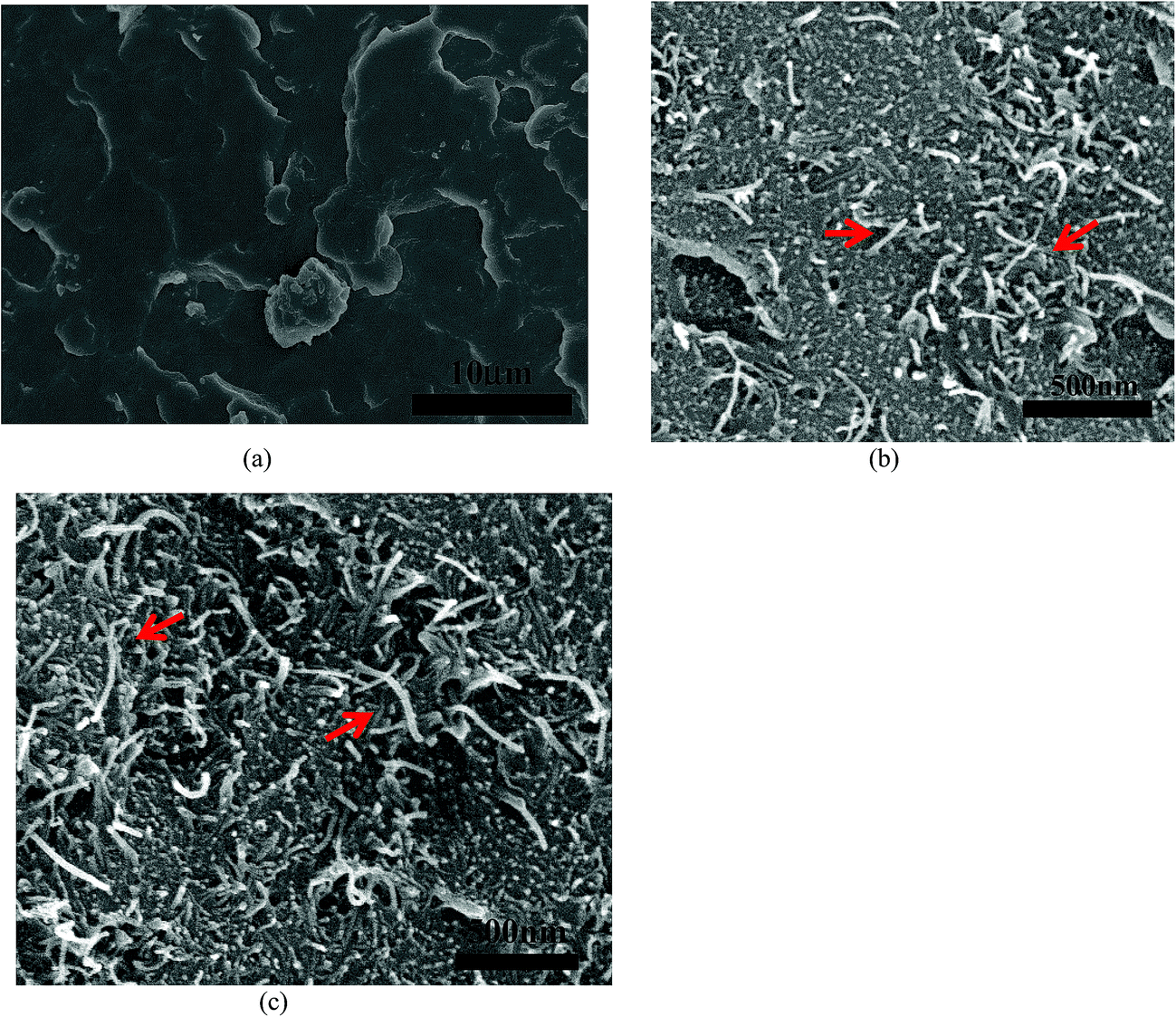 | ||
| Fig. 1 Morphology of PVDF (a) and PVDF + 1% MWNT composite (b) and PVDF + 2% MWNT composite (c) observed under SEM showing good dispersion of MWNTs (red arrows). | ||
3.1 Characterization of PVDF–MWNT substrates
 | (2) |
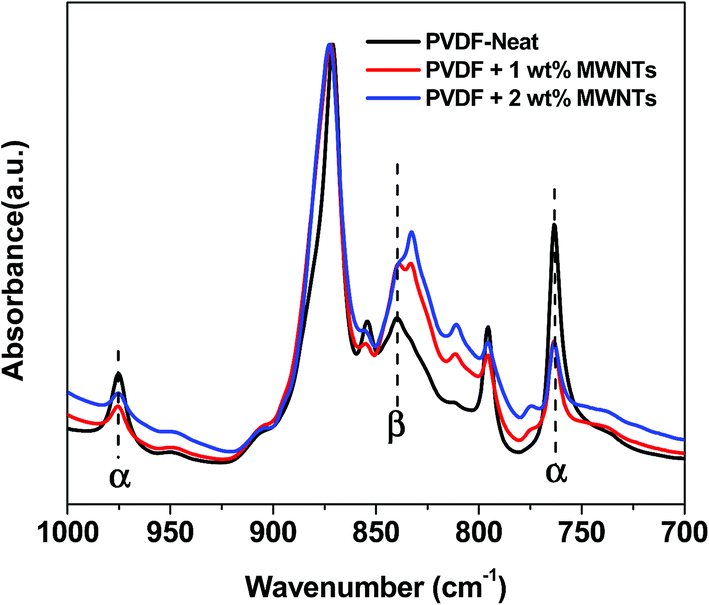 | ||
| Fig. 2 FTIR absorption spectra of PVDF + MWNT confirming the presence of β phase in the composites. The amount of β phase is found to increase with the addition of MWNTs. | ||
The analysis of WAXD patterns obtained for PVDF, PVDF + 1% MWNT and PVDF + 2% MWNT composites is given in the ESI (Fig. S2†) and leads to a similar conclusion. The pattern for PVDF shows standard peaks corresponding to the monoclinic α phase at 2θ ca. 17°, the strongest peak at 2θ ca. 20° and at 2θ ca. 27°. The patterns for PVDF + MWNT composites do contain these peaks but with significantly reduced intensities. The peak broadening in the range of 19–22° indicates the presence of a peak at 2θ ca. 21° corresponding to the orthorhombic β-phase.37,38 Examining the relative intensities of α and β-phase peaks, it is seen that the fraction of β-phase is much higher in PVDF–MWNT composites than in neat PVDF, but among the composites themselves, there is a minor change in the relative amounts of these phases.
| σdc ∝ (p − pc)n | (3) |
| σac(ω) = σdc(ω) + Aωm | (4) |
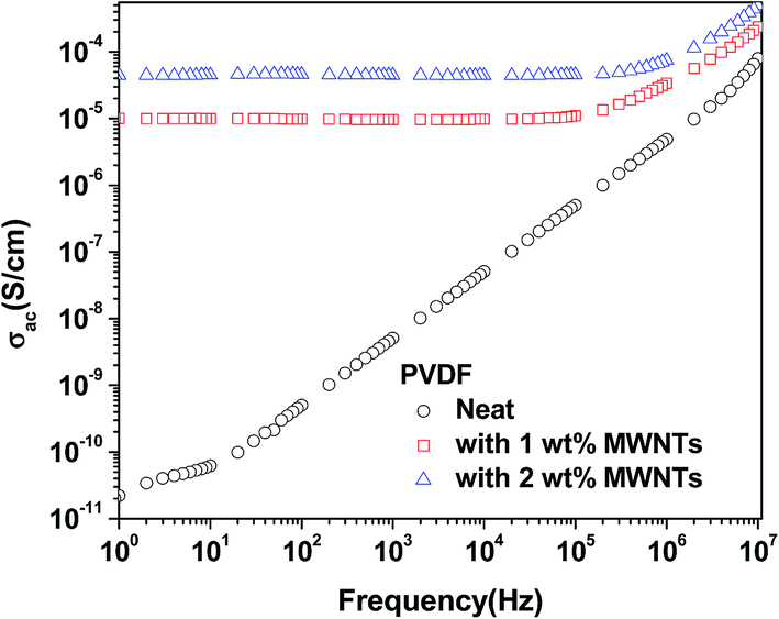 | ||
| Fig. 3 Frequency dependent conductivity of neat PVDF and PVDF–MWNTs composite. | ||
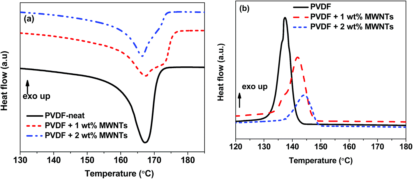 | ||
| Fig. 4 Melting (a) and crystallization (b) thermograms of PVDF–MWNT composites. | ||
Apart from this the mechanical properties of the composites have been determined as we expect an enhancement of tensile strength with the addition of MWNTs due to their remarkably high elastic modulus and tensile strength of carbon nanotubes (Young's modulus ∼1 TPa and tensile strengths in the range 11–63 GPa).44 The relevant properties are tabulated in Table 1 and the stress–strain response is provided in ESI (Fig. S3†). It is to be noted that, addition of MWNTs leads to a stiffer composite evident from the decreasing elongation at break and an increase in tensile strength (Table 1). This is mainly due to the fact that sidewall of MWNTs acts as nucleating agents during the crystallization of PVDF leading to stiffer composite.45 Moreover, it is generally observed the loading of nanoparticles decreases the elongation at break of the composite due to the poor interfacial adhesion and inefficient stress transfer between polymers and MWNTs.46
3.2 Melting and crystallization behaviour
DSC thermographs of the first heating cycle show the appearance of a melting peak of the composites (Fig. 4a). The endothermic peak of the composite filled with 1 and 2% MWNTs is broadened because of the increase in β-phase. We observe a minor change in Tm with the addition of MWNTs and together with the FT-IR and WAXD results (Fig. 2 and S2†), can be taken as an indication that apart from α and β-phases, other polymorphs of PVDF are absent in PVDF–MWNT composites. Moreover, MWNT filled composites show a slightly larger enthalpy of fusion than the neat PVDF. This indicates a minor increase in crystallinity with the addition of MWNTs. The % crystallinity can be estimated by the following equation,47where ΔHm is enthalpy of fusion, ΔH0m is the hypothetical heat of fusion of 100% crystalline PVDF (taken to be 104.7 J g−1)48 and w is the weight fraction of the polymer in the composite. The Xc values of the composites is listed in Table 1. The cooling cycle shows exothermic peaks (peaks in +Y direction-Exo up) for Tc (Fig. 4b). With the addition of nanofillers the Tc is observed to increase considerably and such observations indicate the role of MWNTs as heterogeneous nucleating agents thereby increasing the crystallinity in PVDF–MWNT composites (see also Table 1). Further analysis of crystallization kinetics by following Avrami model for isothermal and non-isothermal crystallization kinetics is shown in the ESI.† The parameters derived from the analysis indicate that irrespective of the crystallization temperature, the value of k, the rate of crystallization increases dramatically with the addition of MWNTs, which signifies the role of nanotubes in heterogeneous nucleation.49 Increasing the fraction of MWNTs from 1 to 2%, the rate of crystallization does not alter much as 1% MWNTs could be sufficient enough to provide nucleation sites. Similar observations have been reported by Song et al.50 in PVDF/La2O3 and by Lim et al.51 in PVDF–MWNT composites.
3.3 Cell viability in the presence of electric field
As mentioned in the earlier in the article, electric fields can potentially induce various changes in cell behaviour on conducting substrates, be it a change in morphology, cell number or in cell functionality. It can be reiterated further that previous studies show that depending on the conductivity of the substrate, only a narrow window of electric field parameters in the range of 100 mV cm−1 to 10 V cm−1 can elicit such favourable responses. Substrates with lesser conductivity require higher electric fields to cause a significant change in the cell response, but higher electric fields (more than 10 V cm−1) are observed to cause cell death even on conducting substrates and generally not used in cell culture experiments.27,52,53In the above context and taking into account the conductivity of PVDF–MWNT composites, our experiments with electric fields were restricted to electric fields <2 V cm−1. The cell viability of C2C12 mouse myoblast cells seeded on PVDF–MWNT composites after electrical stimulation with 0.5 V cm−1, 0.75 V cm−1, 1 V cm−1 and 2 V cm−1 for three days (10 min every 24 h) was evaluated by the MTT assay. Also, the effect of addition of MWNTs to PVDF matrix on the cell viability is examined without the influence of electric field. The cell viability in the two cases (with and without electric field) is calculated according to eqn (1) with respect to that of biocompatible glass coverslips, which is taken as the control.
The cell viability results presented in the Fig. 5 quantify the effect of the addition of MWNTs to PVDF on cell proliferation in addition to the effect of electric field stimulation after 3 days. It is seen that there is no statistically significant difference (p < 0.05) in the cell viability between PVDF, PVDF + 1% MWNT and PVDF + 2% MWNT without any electric field treatment, implying that the addition of MWNTs (1 and 2%) is not detrimental to the cell viability both with respect to the control and the bioinert neat PVDF. The results of electric field stimulation are shown adjacent to their untreated counterparts to obtain a better contrast and correlation between the cause (addition of MWNTs, electric field) and the effect which is observed as a change in cell viability. It is observed that on the insulating PVDF substrate, the application of electric field resulted in a statistically significant reduction in cell viability at higher electric fields (0.75, 1 and 2 V cm−1). This follows from the well-established hypothesis that cell–electric field interaction is more favourable on conducting substrates rather than on insulating substrates.26,27,32,52 This hypothesis is tested with conducting PVDF–MWNT composites and it is indeed found that electric field stimulation of C2C12 cells on PVDF + 2% MWNT substrates which possess the highest conductivity (5 × 10⁻⁵ S cm−1) supports cell proliferation in electric field stimulated culture conditions. In the initial stages, 0.5 V cm−1 was used for stimulating cells on all three substrates. The results show no statistically significant difference in viabilities, indicating that 0.5 V cm−1 is inefficient in changing cell culture microenvironment. When the electric field is increased to 0.75 V cm−1, a drastic decrease in cell viability on PVDF and a slight but statistically significant decrease in PVDF + 1% MWNT is observed. In contrast, PVDF + 2% MWNT shows an increase in the viability which is significant compared to both PVDF + 2% MWNT without electric field stimulation and PVDF (with EF = 0.75 V cm−1), which suggests the influence of conductivity on cell viability under electric field stimulation. The positive response of cells seeded on PVDF + 2% MWNT was particularly significant with exposure to electric field strength of 1 V cm−1 and was observed to cause the highest modulation in cell proliferation. On the other hand, the cell viability on PVDF + 1% MWNT was reduced when exposed to 0.75 V cm−1 and 1 V cm−1. This is a significant observation considering the improvements in substrate conductivity and β-phase content in PVDF + 2% MWNT (5 × 10⁻⁵ S cm−1 and 59%) compared to PVDF + 1% MWNT (10−5 S cm−1 and 56%). In addition, the fact that cell viability in the samples without electric field treatment show no statistical difference with respect to each other, whereas electric field stimulation was observed to induce a contrasting behaviour indicate the importance of external field stimulation in modulating cell responses on conducting biomaterials. However, when the electric field intensity was increased to 2 V cm−1 to determine if the trend continues at higher electric fields, a drastic reduction in cell viability in all three composites was observed. In the case of PVDF it can even be considered cytotoxic (viability < 60%). Many studies in the past have demonstrated the cell type and substrate conductivity dependence of optimal electric field on both conducting ceramic and polymer substrates and the present set of experiments is another case in point.27,52,53
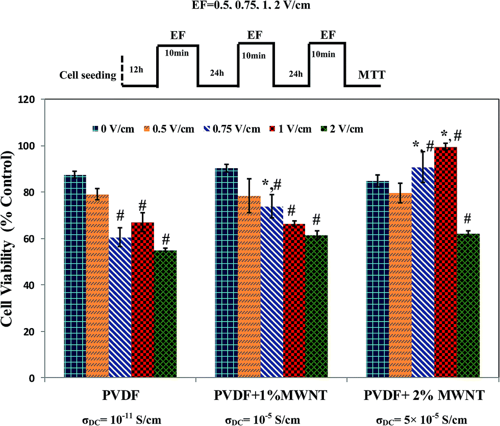 | ||
| Fig. 5 A comparative representation of effect of different electric fields on C2C12 mouse myoblast cell viability. The data is represented as mean value ± standard deviation. * indicates a significant with respect to comparison with corresponding values of PVDF and # indicates significant difference with a comparison within the group with respect to 0 V cm−1. | ||
3.4 Cell morphology on electric field stimulated PVDF–MWNT composites
The morphology and spreading of C2C12 cells on PVDF–MWNT composites after 3 days in culture was examined by fluorescence imaging and scanning electron microscopy. The representative fluorescence images are provided in Fig. 6 after electric field treatment with 1 V cm−1 for 3 days. The fluorescence images of cultured cells with stained nuclei (blue) and cytoskeleton (green) reveal that the PVDF + 2% MWNT surface is fully covered with well grown muscle cells. Moreover, another feature that can be noticed in the fluorescence images is the alignment of cells (see Fig. 6d), an indication of onset of differentiation of myoblast cells into myotubes, which is believed to be aided by substrate conductivity.54 While PVDF + 1% MWNT and PVDF show a decrease in the cell number compared to control, there seems to be some alignment in the cells on PVDF + 1% MWNT (see Fig. 6c). SEM images on other hand show enhanced cell spreading on PVDF + 2% MWNT composites compared to other substrates. The cellular bridge formation (see Fig. 7d) enables the cell–cell contact to be established, which is essential for efficient cell signalling process involved in cell proliferation and differentiation. The above observations indicate that a longer duration of culture with a similar protocol of electric field stimulation could induce early stage differentiation into myotubes on PVDF + 2% MWNT composites. | ||
| Fig. 6 Cell morphology observations through fluorescence imaging of control (a), PVDF (b), PVDF + 1% MWNT (c) and PVDF + 2% MWNT (d) after electric field treatment with 1 V cm−1 for 3 days. Increased cell number and cell alignment was observed with respect to control in PVDF + 2% MWNT (white arrows in d). Significant reduction in cell numbers on PVDF and PVDF + 1% MWNTs were observed, though it appears that there is some alignment in the limited cell number observed on PVDF + 1% MWNT (c). | ||
 | ||
| Fig. 7 Cell morphology observations through SEM showing (a) control, (b) PVDF (c) PVDF + 1% MWNT and (d) PVDF + 2% MWNT after electric field stimulation for 3 days. Enhanced cell spreading and cell–cell contact (black arrows in d) was observed in PVDF + 2% MWNT composites. | ||
3.5 Correlation between properties of PVDF–MWNT and electric field induced cell viability
It can be reiterated at this stage that though the conductivity of PVDF + 2% MWNT is slightly higher than PVDF + 1% MWNT, a positive response to the electric field is recorded. In contrast, whereas insulating PVDF and conducting PVDF + 1% MWNT exhibit a negative effect with respect to the cellular response to the optimal electric field (1 V cm−1). In order to confirm if this effect might have its provenance in other properties of the samples, the wetting behaviour was analysed.The wetting angle is one of the important parameters which can affect cell adhesion and proliferation on substrates.55 The wetting angles for PVDF and PVDF–MWNT composites were found to be significantly different, due to addition of high surface energy MWNTs. PVDF was more hydrophilic with a contact angle of 70.5 ± 3°, whereas it was observed to be 90.3 ± 4° and 94.8 ± 4° for PVDF with 1% and 2% MWNT respectively. Even though the cells prefer a hydrophilic substrate, this does not seem to be the cause for the difference in the cell response as there is not significant change in the cell viability of untreated samples on PVDF and PVDF–MWNT composites.
Another parameter which can alter the cell response is the fraction of β-phase. The β-phase is generally reported to favour cell adhesion and proliferation. In particular, studies have confirmed that β-phase films enhance fibronectin deposition at cell–material interface, which aids in cell adhesion and spreading and promote a homogenous cell distribution compared to α phase films.56 Apart from this, there are also reports that suggest the cell morphology is also very strongly dependent on the α–β phase composition in PVDF films and α phase is more favoured.57,58 Even though the fraction of α and β-phase is similar in the bulk PVDF–MWNT composites in the present study (see Fig. 2 and S2†), the β-phase fraction on the surface of the samples needs to be considered, as cell proliferation is mainly a surface phenomenon. Also, the synergistic effect due to the interaction between the β-phase and electric field during cell culture is something that has not been well explored and will be the subject for future investigation.
4. Conclusions
On the basis of experimental results on melt mixed PVDF–MWNT composites with a focus on characterization and cell viability under the influence of electric field, the following conclusions can be drawn:(i) The melt mixed composites were observed to exhibit a good dispersion of MWNTs in the PVDF matrix. FT-IR shows that the amount of β-phase increases significantly with the addition of 1% MWNT, but further addition of MWNTs results only in a minor improvement in % β-phase.
(ii) The sharp increase in the DC conductivity of PVDF + 1% MWNT (10−5 S cm−1) composites indicates that the percolation threshold is less than 1%. Further increase in amount of MWNTs did not result in an appreciable change in the conductivity (5 × 10⁻⁵ S cm−1 for PVDF + 2% MWNT).
(iii) C2C12 mouse myoblast cell viability results suggest that the addition of 1% and 2% MWNTs to the PVDF matrix does not cause any cytotoxic effect in vitro, without any external field stimulation.
(iv) The optimal electric field to enhance cell proliferation is found to be 1 V cm−1 for PVDF + 2% MWNT and the application of similar electric field strength for other samples (PVDF and PVDF + 1% MWNT) reduces the cell viability significantly.
The results of this study confirm the synergy among the amount of β-phase, conductivity and electric field intensity in modulating the cell proliferation on PVDF–MWNT substrates. The continuation of the present study to check if a further increase in the fraction of β-phase affects the cell functionality under the influence of electric field will be interesting.
Acknowledgements
The authors would like to acknowledge the financial support provided by Department of Science and Technology (DST), Government of India and Department of Biotechnology (DBT), Government of India under ‘Centers of Excellence and Innovation in Biotechnology’ scheme through the center of excellence project – Translational Center on Biomaterials for Orthopedic and Dental Applications.References
- C. K. Chiang, C. Fincher Jr, Y. Park, A. Heeger, H. Shirakawa, E. Louis, S. Gau and A. G. MacDiarmid, Phys. Rev. Lett., 1977, 39, 1098 CrossRef CAS.
- F. Carpi and E. Smela, Biomedical Applications of Electroactive Polymer Actuators, A John Wiley and Sons, Ltd., Chichester, UK, 2009 Search PubMed.
- K. J. Kim and S. Tadokoro, Artificial Muscles and Sensors, Springer, London, United Kingdom, 2007, p. 291 Search PubMed.
- C. E. Chidsey and R. W. Murray, Science, 1986, 231, 25–31 CAS.
- C. Huang, R. Klein, F. Xia, H. Li, Q. Zhang, F. Bauer and Z. Cheng, IEEE Trans. Dielectr. Electr. Insul., 2004, 11, 299–311 CrossRef CAS.
- P. Novák, K. Müller, K. Santhanam and O. Haas, Chem. Rev., 1997, 97, 207–282 CrossRef.
- J. Song, Y. Wang and C. Wan, J. Power Sources, 1999, 77, 183–197 CrossRef CAS.
- R. D. Kornbluh, R. Pelrine, J. Joseph, R. Heydt, Q. Pei and S. Chiba, Proc. SPIE, 1999, 3669, 149–161 CrossRef CAS.
- E. Biddiss and T. Chau, Med. Eng. Phys., 2006, 28, 568–578 CrossRef PubMed.
- Y. Bar-Cohen, J. Spacecr. Rockets, 2002, 39, 822–827 CrossRef CAS.
- S. Chiba, S. Stanford, R. Pelrine, R. Kornbluh and H. Prahlad, Journal of the Robotics Society of Japan, 2006, 24, 466–470 CrossRef.
- J.-M. Pernaut and J. R. Reynolds, J. Phys. Chem. B, 2000, 104, 4080–4090 CrossRef CAS.
- D. H. Kim, M. Abidian and D. C. Martin, J. Biomed. Mater. Res., Part A, 2004, 71, 577–585 CrossRef PubMed.
- A. J. Lovinger, in Developments in crystalline polymers—1, Springer, 1982, pp. 195–273 Search PubMed.
- A. J. Lovinger, Science, 1983, 220, 1115–1121 CAS.
- N. Murayama, K. Nakamura, H. Obara and M. Segawa, Ultrasonics, 1976, 14, 15–24 CrossRef CAS.
- P. Ueberschlag, Sens. Rev., 2001, 21, 118–126 CrossRef.
- M. Sharma, G. Madras and S. Bose, Phys. Chem. Chem. Phys., 2014, 16, 14792–14799 RSC.
- V. Sencadas, R. Gregorio Jr and S. Lanceros-Méndez, J. Macromol. Sci., Part B: Phys., 2009, 48, 514–525 CrossRef CAS.
- W. Huang, K. Edenzon, L. Fernandez, S. Razmpour, J. Woodburn and P. Cebe, J. Appl. Polym. Sci., 2010, 115, 3238–3248 CrossRef CAS.
- D. Chen, M. Wu, W. Wang and T. Liu, J. Macromol. Sci., Part B: Phys., 2010, 49, 1069–1082 CrossRef CAS.
- V. Sencadas, S. Lanceros-Mendez and J. Mano, Thermochim. Acta, 2004, 424, 201–207 CrossRef CAS.
- A. Lund, C. Gustafsson, H. Bertilsson and R. W. Rychwalski, Compos. Sci. Technol., 2011, 71, 222–229 CrossRef CAS.
- T. Kaura, R. Nath and M. Perlman, J. Phys. D: Appl. Phys., 1991, 24, 1848 CrossRef CAS.
- J. Y. Wong, R. Langer and D. E. Ingber, Proc. Natl. Acad. Sci. U. S. A., 1994, 91, 3201–3204 CrossRef CAS.
- C. E. Schmidt, V. R. Shastri, J. P. Vacanti and R. Langer, Proc. Natl. Acad. Sci. U. S. A., 1997, 94, 8948–8953 CrossRef CAS.
- G. Thrivikraman, G. Madras and B. Basu, Biomaterials, 2014, 35, 6219–6235 CrossRef CAS PubMed.
- T.-I. Chao, S. Xiang, C.-S. Chen, W.-C. Chin, A. Nelson, C. Wang and J. Lu, Biochem. Biophys. Res. Commun., 2009, 384, 426–430 CrossRef CAS PubMed.
- H. Castano, E. A. O'Rear, P. S. McFetridge and V. I. Sikavitsas, Macromol. Biosci., 2004, 4, 785–794 CrossRef CAS PubMed.
- F. Jonas and L. Schrader, Synth. Met., 1991, 41, 831–836 CrossRef CAS.
- W. W. Focke, G. E. Wnek and Y. Wei, J. Phys. Chem., 1987, 91, 5813–5818 CrossRef CAS.
- M. P. Prabhakaran, L. Ghasemi-Mobarakeh, G. Jin and S. Ramakrishna, J. Biosci. Bioeng., 2011, 112, 501–507 CrossRef CAS PubMed.
- T. Hadlock, C. Sundback, D. Hunter, M. Cheney and J. P. Vacanti, Tissue Eng., 2000, 6, 119–127 CrossRef CAS PubMed.
- G. H. Kim, S. M. Hong and Y. Seo, Phys. Chem. Chem. Phys., 2009, 11, 10506–10512 RSC.
- B. Luo, X. Wang, Y. Wang and L. Li, J. Mater. Chem. A, 2014, 2, 510–519 CAS.
- P. Khanchaitit, K. Han, M. R. Gadinski, Q. Li and Q. Wang, Nat. Commun., 2013, 4, 2845 Search PubMed.
- N. I. Makarevich and V. N. Nikitin, Polym. Sci. U.S.S.R., 1965, 7, 1843–1849 CrossRef.
- Y. L. Gal'perin, Y. V. Strogalin and M. P. Mlenik, Polym. Sci. U.S.S.R., 1965, 7, 1031–1039 CrossRef.
- Y. Zeng, P. Liu, J. Du, L. Zhao, P. M. Ajayan and H.-M. Cheng, Carbon, 2010, 48, 3551–3558 CrossRef CAS.
- J. T. Wescott, P. Kung and A. Maiti, Appl. Phys. Lett., 2007, 90, 033116 CrossRef.
- T. W. Ebbesen, H. J. Lezec, H. Hiura, J. W. Bennett, H. F. Ghaemi and T. Thio, Nature, 1996, 382, 54–56 CrossRef CAS.
- S. Biswas, G. P. Kar and S. Bose, Nanoscale, 2015, 11334–11351 RSC.
- S. Biswas, G. P. Kar and S. Bose, J. Mater. Chem. A, 2015, 12413–12426 CAS.
- B. Arash, Q. Wang and V. Varadan, Sci. Rep., 2014, 4, 6479 CrossRef CAS PubMed.
- Z. Spitalsky, D. Tasis, K. Papagelis and C. Galiotis, Prog. Polym. Sci., 2010, 35, 357–401 CrossRef CAS.
- G. P. Kar, S. Biswas and S. Bose, Phys. Chem. Chem. Phys., 2015, 17, 1811–1821 RSC.
- L. Ren, X. Meng, J.-W. Zha and Z.-M. Dang, RSC Adv., 2015, 5, 65167–65174 RSC.
- C. Marega and A. Marigo, Eur. Polym. J., 2003, 39, 1713–1720 CrossRef CAS.
- J. Kim, S. Kwak, S. M. Hong, J. R. Lee, A. Takahara and Y. Seo, Macromolecules, 2010, 43, 10545–10553 CrossRef CAS.
- J. Song, C. Lu, D. Xu, Y. Ni, Y. Liu, Z. Xu and J. Liu, Polym. Int., 2010, 59, 954–960 CrossRef CAS.
- J. Y. Lim, J. Kim, S. Kim, S. Kwak, Y. Lee and Y. Seo, Polymer, 2015, 62, 11–18 CrossRef CAS.
- A. K. Dubey and B. Basu, J. Am. Ceram. Soc., 2014, 97, 481–489 CrossRef CAS.
- S. Jain, A. Sharma and B. Basu, Biomaterials, 2013, 34, 9252–9263 CrossRef CAS PubMed.
- G. Thrivikraman, P. K. Mallik and B. Basu, Biomaterials, 2013, 34, 7073–7085 CrossRef CAS PubMed.
- L. Richert, F. Vetrone, J. H. Yi, S. F. Zalzal, J. D. Wuest, F. Rosei and A. Nanci, Adv. Mater., 2008, 20, 1488–1492 CrossRef CAS.
- C. Ribeiro, J. Panadero, V. Sencadas, S. Lanceros-Méndez, M. Tamaño, D. Moratal, M. Salmerón-Sánchez and J. G. Ribelles, Biomed. Mater., 2012, 7, 035004 CrossRef CAS PubMed.
- Y. Low, N. Meenubharathi, N. Niphadkar, F. Boey and K. Ng, J. Biomater. Sci., Polym. Ed., 2011, 22, 1651–1667 CrossRef CAS PubMed.
- Y. K. A. Low, X. Zou, Y. M. Fang, J. L. Wang, W. S. Lin, F. Y. C. Boey and K. W. Ng, Mater. Sci. Eng., C, 2014, 34, 345–353 CrossRef CAS PubMed.
Footnotes |
| † Electronic supplementary information (ESI) available. See DOI: 10.1039/c5ra26104j |
| ‡ These authors contributed equally. |
| This journal is © The Royal Society of Chemistry 2016 |