Insights into the effects of different acids on the formation and electrochemical properties of carbon spherules†
Jiao Yan,
Haixia Wu,
Wenzhuo Shen* and
Shouwu Guo*
Department of Electronic Engineering, School of Electronic Information and Electrical Engineering, Shanghai Jiao Tong University, Shanghai 200240, P. R. China. E-mail: wenzhuoshen@hotmail.com; swguo@sjtu.edu.cn
First published on 1st April 2016
Abstract
Monodispersed and size-controlled carbon spherules have great potential in many different applications. We report here the effects of organic and inorganic acids as catalysts on the formation of carbon spherules through the hydrothermal carbonization of glucose. The as-generated carbon spherules had better monodispersity, a narrower size distribution and easier graphitization when organic dicarboxylic acids were used as catalysts. The carbon spherules produced using organic dicarboxylic acids as catalysts and their corresponding composites with chemically reduced graphene oxide had unique electrochemical properties when used as active materials for anodes in lithium ion batteries. Possible mechanisms of formation of carbon spherules with different inorganic and organic acids are proposed and their structure–property relationships are discussed.
Introduction
As a carbonaceous material, carbon spherules (CSs) with diameters in the range of nanometres to micrometres have attracted attention as a result of their unique morphology, properties and potential applications.1–3 CSs usually have a high specific surface area, a light weight, high strength, good thermal stability and, in some cases, good electrical conductivity. Together, these properties make them useful materials in many applications, such as anodes for lithium ion batteries (LIBs),4 electrodes for supercapacitors,5,6 carriers in drug delivery systems,7 catalysts,8 supports for catalysts9 and as sorbents for chemical purification.10 In addition, CSs have also been used as a scaffold component in structural or functional composite materials.11–13 For example, carbon nanospheres and chemically reduced graphene oxide (CRGO) have been used as building blocks to prepare composites with a uniform three-dimensional (3D) network structure; the as-prepared composites showed good electrochemical performance as anodes for LIBs.13 Similarly, hollow CS/PANI composites used as an electrode in supercapacitors showed an enhanced gravimetric capacitance.11Several protocols have been successfully developed for the preparation of CSs, including chemical vapour deposition,6 arc discharge,14 polymeric templates15 and the hydrothermal treatment of carbohydrates.3,8,16 A variety of CSs with different sizes, surface functionalities and controlled internal textures have been produced. The hydrothermal treatment of carbohydrates or other biomass materials has been used most often as a result of the following advantages: abundant precursor (raw) materials; cost-effective operation procedures; bulk scale production; and the simplicity of controlling the shape and size of the as-prepared CSs. However, the hydrothermal reactions of carbohydrates and other biomass materials usually take place very slowly, the conversion to CSs is relatively low and the as-produced CSs tend to be interconnected with each other, which may affect further processing and applications.1,2,17–21 To obtain monodispersed CSs, the concentration of reactants, the hydrothermal reaction time and the reaction temperature used for different carbohydrates and types of biomasses have been evaluated systematically.3,22,23 It has been shown that, by varying the reaction conditions in the conversion of the precursor materials to CSs, the size of the CSs can be improved, although, in most instances, coalescence among the CSs cannot be avoided.22,23 Several mineralizers (catalysts) have recently been introduced into the hydrothermal reactions of carbohydrates.18 For instance, acids such as nitric acid,24 acrylic acid25 and glutaric acid13 have been used as mineralizers and it has been shown that the hydrothermal reactions of carbohydrates can be speeded up, and the size and dispersion of the CSs can be tuned by controlling the pH of the reaction system. This may be because the mineralizer in the hydrothermal reaction system not only accelerates the dehydration and polymerization of the carbohydrate molecules, but also generates diverse functional groups on the CSs.25 This may also result in novel properties for the CSs and enhance further processing of the CSs.26 However, only a few acids have been investigated as mineralizers for the dehydration and carbonization of carbohydrates; the detailed catalytic mechanism of the acids is still unclear and the effects of different acids on the evolution of the size, shape and internal texture of the CSs have not yet been determined. Although there are many reports of the fabrication and application of CSs, it is still challenging to control the size, surface functionality and internal texture of CSs.
We systematically studied the effects of different acids, including organic and inorganic acids, on the hydrothermal reaction of glucose and the as-prepared CSs. A series of acids (malonic acid, butanedioic acid, glutaric acid, adipic acid, sulfuric acid, nitric acid, hydrochloric acid and phosphoric acid) was used as mineralizers in the reaction system and the ratio of the acids to glucose was varied. The size, composition, surface functionality and structure of the as-prepared CSs were characterized using scanning electron microscopy (SEM), X-ray powder diffraction (XRD) and FTIR spectrometry. It was shown that by controlling the concentrations of organic dicarboxylic acids, monodispersed and functionalized CSs could be synthesized. The composites of as-obtained CSs and CRGO sheets were prepared and used as anodes in coin cells. The composites with CSs prepared using organic dicarboxylic acids had a better electrochemical performance as anodes in LIBs than those prepared using inorganic acids as mineralizers. The mechanism of formation of the CSs and the relations between the structure of the composites and their electrochemical properties were investigated.
Experimental
Preparation of CSs and CRGO/CS composites
The CSs were prepared using a hydrothermal procedure with glucose as the carbon precursor and various acids (malonic acid, butanedioic acid, glutaric acid, adipic acid, sulfuric acid, hydrochloric acid, nitric acid and phosphoric acid) as mineralizers. When an organic acid was used as the mineralizer, 28 mmol of glucose and 0.75 mmol of organic acid were dissolved in 40 mL of deionized water (the pH of the solution was c. 2.5). When an inorganic acid was used, 28 mmol of glucose were dissolved in 40 mL of deionized water and then a measured amount of inorganic acid was added to adjust the solution pH to 2.5. The solutions were transferred into Teflon-lined stainless-steel autoclaves and heated at 180 °C for 5 h. After cooling naturally to room temperature, the solid products were separated by filtration, washed with deionized water and ethanol, and oven-dried at 60 °C for 8 h. The CSs obtained were named simply as MCSs, BCSs, GCSs, ACSs, SCSs, HCSs, NCSs and PCSs after the mineralizer used (malonic acid, butanedioic acid, glutaric acid, adipic acid, sulfuric acid, hydrochloric acid, nitric acid and phosphoric acid, respectively). To study the influence of the concentration of organic acid (using glutaric acid as a representative), GCSs were prepared by adding 0.75, 1.5, 2.25, 3.75 and 7.5 mmol of glutaric acid to the reaction system. PCSs were similarly prepared in parallel by adding 0.05, 0.15, 0.2 and 0.25 mmol of phosphoric acid to the reaction system. For further testing for possible graphitization, the as-prepared CSs were annealed in an argon (Ar) gas flow containing 5% H2 for 3, 6 and 10 h at 900 °C.The graphene oxide (GO) used for the preparation of CRGO/CSs composites was prepared using a previously reported modified Hummers method.27 To make the CRGO/CS composites, aqueous suspensions of GO and CS were fully mixed under ultrasonication with GO to CS weight ratios of 1![[thin space (1/6-em)]](https://www.rsc.org/images/entities/char_2009.gif) :
:![[thin space (1/6-em)]](https://www.rsc.org/images/entities/char_2009.gif) 1, 5
1, 5![[thin space (1/6-em)]](https://www.rsc.org/images/entities/char_2009.gif) :
:![[thin space (1/6-em)]](https://www.rsc.org/images/entities/char_2009.gif) 1, 10
1, 10![[thin space (1/6-em)]](https://www.rsc.org/images/entities/char_2009.gif) :
:![[thin space (1/6-em)]](https://www.rsc.org/images/entities/char_2009.gif) 1 and 20
1 and 20![[thin space (1/6-em)]](https://www.rsc.org/images/entities/char_2009.gif) :
:![[thin space (1/6-em)]](https://www.rsc.org/images/entities/char_2009.gif) 1. The water was then removed by vacuum rotary evaporation at 70 °C. The as-obtained composites were further annealed at 900 °C in an Ar gas flow containing 5% H2 for 3 h to reduce the GO to CRGO and to partially graphitize the CSs.
1. The water was then removed by vacuum rotary evaporation at 70 °C. The as-obtained composites were further annealed at 900 °C in an Ar gas flow containing 5% H2 for 3 h to reduce the GO to CRGO and to partially graphitize the CSs.
Characterization
SEM images were acquired on an Ultra 55 field-emission scanning electron microscope (Zeiss, Germany). Energy-dispersive X-ray spectrometry (EDS) data were obtained using the same SEM system. The FTIR spectra were recorded on a Vertex 70 FTIR spectrometer (Bruker, Germany). XRD patterns were obtained on a D8 ADVANCE PC diffractometer (Bruker, Germany) using Cu/Kα radiation (λ = 1.55406 Å).Measurement of electrochemical properties
The electrochemical performance of the CSs and the CRGO/CS composites were studied in coin cells. The working electrodes for the coin cells were prepared by mixing the as-obtained CRGO/CS composites (as the active materials) with poly(vinyldifluoride) and carbon black (Super-P) (8![[thin space (1/6-em)]](https://www.rsc.org/images/entities/char_2009.gif) :
:![[thin space (1/6-em)]](https://www.rsc.org/images/entities/char_2009.gif) 1
1![[thin space (1/6-em)]](https://www.rsc.org/images/entities/char_2009.gif) :
:![[thin space (1/6-em)]](https://www.rsc.org/images/entities/char_2009.gif) 1 w/w) in 1-methyl-2-pyrrolidinone to obtain a slurry. The slurry mixture was coated on Cu foil at a thickness of 10 μm, dried at 110 °C for 12 h and finally cut into circular discs 12 mm in diameter. The mass loading of the active materials on each circular disc was c. 0.8 mg. A thin Li plate was used as the counter electrode and the electrolyte was 1 M LiPF6 in 1
1 w/w) in 1-methyl-2-pyrrolidinone to obtain a slurry. The slurry mixture was coated on Cu foil at a thickness of 10 μm, dried at 110 °C for 12 h and finally cut into circular discs 12 mm in diameter. The mass loading of the active materials on each circular disc was c. 0.8 mg. A thin Li plate was used as the counter electrode and the electrolyte was 1 M LiPF6 in 1![[thin space (1/6-em)]](https://www.rsc.org/images/entities/char_2009.gif) :
:![[thin space (1/6-em)]](https://www.rsc.org/images/entities/char_2009.gif) 1 ethylene carbonate and dimethyl carbonate. The coin cells were assembled in an argon-filled glove box. Galvanostatic charge–discharge measurements were carried out on a LAND CT2001A electrochemical workstation (Wuhan, China) at various current densities in the voltage range 0.01–3 V. Electrochemical impedance spectrometry data were recorded by applying a perturbation voltage of 5 mV in the frequency range 0.01 Hz to 100 kHz using a PGSTAT 302N electrochemical workstation (Merohm, Switzerland).
1 ethylene carbonate and dimethyl carbonate. The coin cells were assembled in an argon-filled glove box. Galvanostatic charge–discharge measurements were carried out on a LAND CT2001A electrochemical workstation (Wuhan, China) at various current densities in the voltage range 0.01–3 V. Electrochemical impedance spectrometry data were recorded by applying a perturbation voltage of 5 mV in the frequency range 0.01 Hz to 100 kHz using a PGSTAT 302N electrochemical workstation (Merohm, Switzerland).
Results and discussion
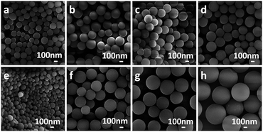
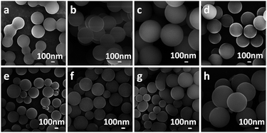
To evaluate the influence of acids as mineralizers on the hydrothermal reactions of carbohydrates, several dicarboxylic acids with different alkyl chains and an assumed high solubility in water were investigated. Fig. 1a–d shows that, after 5 h of hydrothermal treatment at 180 °C (reactants 28 mmol of glucose, 1.5 mmol of dicarboxylic acid, 40 mL of deionized water), MCSs, BCSs, GCSs and ACSs were generated. All the as-obtained CSs had diameters in the range of several hundred nanometres and showed moderate monodispersity. For comparison, the hydrothermal reaction of glucose was also carried out under the same conditions, but without using any acid (Fig. S1†); the as-obtained CSs were severely aggregated and formed a necklace-like structure. A series of hydrothermal reactions of glucose with glutaric acid as mineralizer were explored by shortening the reaction times to 2 and 1 h, but keeping the other reaction conditions the same (28 mmol of glucose, 1.5 mmol glutaric acid, 40 mL of deionized water, 180 °C). No CS was formed after a reaction time of 1 h. After a reaction time of 2 h, CSs formed, but they were cross-linked to form a necklace-like chain (Fig. S2†). This shows that the CSs tend to cross-link with each other in the early stages of the reaction. To further investigate the effect of the concentration of dicarboxylic acid, the amount of glutaric acid in the reaction system was changed to 0.75, 2.25, 3.75 and 7.5 mmol, keeping the other reaction conditions the same. Fig. 1e–h shows that the average size of the as-generated GCSs increased with increasing glutaric acid concentration. Specifically, when the amount of glutaric acid was increased from 0.75 to 7.5 mmol, the average diameter of the GCSs increased from 200 to 700 nm (Fig. 1e and h). We propose that the conversion of glucose to CSs was realized through two steps: dehydration and polymerization.3,18,28–30 At high temperatures, glucose was dehydrated in aqueous solution to hydroxymethylfurfural (HMF) and then the nuclei of CSs were formed by the polymerization of HMF and grew by further polymerization of the HMF or the glucose molecules.18,29 It is well known that acids can accelerate both the dehydration and polymerization procedure. However, the fact that the average size increased with increasing concentrations of glutaric acid in the reaction system suggests that the acid might speed up the polymerization of HMF more efficiently than dehydration. However, if the dehydration reaction is faster than the polymerization reaction, then more HMF molecules should accumulate in the reaction system and thus more CSs nuclei should be formed. If the rate of polymerization is faster than the dehydration reaction, the CSs should grow faster and larger CSs should be obtained. Therefore we suggest that the organic dicarboxylic acids should be able to accelerate the polymerization of HMF more efficiently than the dehydration reaction.For comparison, several common inorganic acids (H2SO4, HNO3, HCl and H3PO4) were also used as mineralizers for the hydrothermal conversion of glucose to CSs. The pH values for the reaction solutions with different inorganic acids were controlled to c. 2.5, the same as the reaction with dicarboxylic acid. Fig. 2a–d show that, with the same reaction time and temperature (5 h, 180 °C), the monodispersed CSs were only generated by the reaction with H3PO4 as a mineralizer. The CSs produced from the reactions using H2SO4, HNO3 and HCl were agglomerated, implying that H3PO4 is more appropriate than the other inorganic acids as a mineralizer for the hydrothermal conversion of glucose to CSs. To obtain an insight into the effect of the H3PO4 concentration (or the pH of the reaction system), the hydrothermal reactions were conducted with 1.25, 3.75, 5 and 6.25 mM H3PO4, keeping the other reaction conditions the same (28 mmol of glucose, 40 mL of deionized water, 5 h, 180 °C). Fig. 2e–h shows that, similar to the reaction using glutaric acid as mineralizer (Fig. 1), with increasing concentrations of H3PO4 the average size of the as-generated CSs (referred to as PCSs) increased and the size distribution also increased. The reason why the CSs prepared using organic dicarboxylic acids as a mineralizer had a better dispersion and size distribution than those generated with inorganic acids is not yet fully understood. However, we suggest that the α,ω-dicarboxylic molecular character of the organic dicarboxylic acids should have a role in the dehydration or polymerization of the glucose molecules. To clarify this assumption, a monocarboxylic acid, n-valeric acid, was used as a mineralizer and, as shown in Fig. S4,† the as-generated CSs were aggregated. This confirms our view that dicarboxylic acids are more appropriate as mineralizers for the carbonization of glucose.
In addition to size distribution and dispersity, surface functionality is another factor that may affect the processing and applications of CSs. The FTIR spectra (Fig. S5†) showed that all the as-obtained CSs had abundant oxygen-containing groups on the surface. The C![[double bond, length as m-dash]](https://www.rsc.org/images/entities/char_e001.gif) O and C
O and C![[double bond, length as m-dash]](https://www.rsc.org/images/entities/char_e001.gif) C stretching vibrations of the aromatic ring at 1703 and 1620 cm−1 were seen in the FTIR spectra, in addition to O–H stretching vibrations in the range 3000–3700 cm−1, the C–O bending vibration at 1303 cm−1 and the C–O–H bending vibration at 1396 cm−1, indicating that there was a large number of hydroxyl, epoxy and carboxyl groups on the CSs, which agrees with previously reported results.17,19 The carbon and oxygen contents of the as-obtained CSs were determined by EDS. Table S1† shows that the atomic ratios of carbon to oxygen in the MCSs, BCSs, GCSs and ACSs were 82.6
C stretching vibrations of the aromatic ring at 1703 and 1620 cm−1 were seen in the FTIR spectra, in addition to O–H stretching vibrations in the range 3000–3700 cm−1, the C–O bending vibration at 1303 cm−1 and the C–O–H bending vibration at 1396 cm−1, indicating that there was a large number of hydroxyl, epoxy and carboxyl groups on the CSs, which agrees with previously reported results.17,19 The carbon and oxygen contents of the as-obtained CSs were determined by EDS. Table S1† shows that the atomic ratios of carbon to oxygen in the MCSs, BCSs, GCSs and ACSs were 82.6![[thin space (1/6-em)]](https://www.rsc.org/images/entities/char_2009.gif) :
:![[thin space (1/6-em)]](https://www.rsc.org/images/entities/char_2009.gif) 17.4, 78.0
17.4, 78.0![[thin space (1/6-em)]](https://www.rsc.org/images/entities/char_2009.gif) :
:![[thin space (1/6-em)]](https://www.rsc.org/images/entities/char_2009.gif) 22.0, 78.4
22.0, 78.4![[thin space (1/6-em)]](https://www.rsc.org/images/entities/char_2009.gif) :
:![[thin space (1/6-em)]](https://www.rsc.org/images/entities/char_2009.gif) 21.6 and 79.7
21.6 and 79.7![[thin space (1/6-em)]](https://www.rsc.org/images/entities/char_2009.gif) :
:![[thin space (1/6-em)]](https://www.rsc.org/images/entities/char_2009.gif) 20.3, respectively, which are slightly higher than that in the PCSs (75.0
20.3, respectively, which are slightly higher than that in the PCSs (75.0![[thin space (1/6-em)]](https://www.rsc.org/images/entities/char_2009.gif) :
:![[thin space (1/6-em)]](https://www.rsc.org/images/entities/char_2009.gif) 25.0), indicating that there are more oxygen-containing groups in PCSs. However, the SEM images in Fig. 1 and 2e–h suggest that the carbon to oxygen ratio is not a key factor in determining the morphology of the CSs.
25.0), indicating that there are more oxygen-containing groups in PCSs. However, the SEM images in Fig. 1 and 2e–h suggest that the carbon to oxygen ratio is not a key factor in determining the morphology of the CSs.
The XRD patterns of CSs before and after annealing were determined to show the internal textures such as the crystalline state (extent of graphitization) of the CSs. Fig. 3 shows that the as-prepared (before annealing) PCSs and GCSs assumed an amorphous structure. However, after annealing at 900 °C for 3 h in an Ar gas flow containing 5% H2, diffraction peaks centred at 25, 43 and 52° appeared for GCSs, which could be indexed to the (002), (100) and (102) diffractions of graphite (JCPDS-ICDD card no. 41-1487).13 For PCSs, the (002) and (100) diffraction peaks were detected, but the (102) peak was not seen, which reflects the relatively low graphitization of PCSs. The intensities of the diffraction peaks of GCSs increased with increasing annealing temperature and the intensities of the diffraction peaks of the GCSs were always higher than those of PCSs annealed under the same conditions. This suggests that GCSs should be easier to graphitize, which will be important in their applications. The XRD patterns of MCSs, BCSs and ACSs after annealing at 900 °C in an Ar gas flow containing 5% H2 for 3 h are shown in Fig. S6† and reveal that the as-prepared CSs from other organic acids can also be graphitized during thermal annealing.
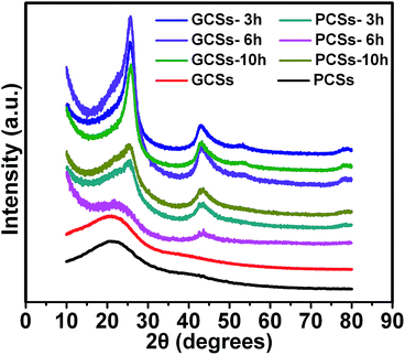 | ||
| Fig. 3 XRD patterns of PCSs and GCSs before and after annealing at 900 °C in an Ar gas flow containing 5% H2 for 3, 6 and 10 h. | ||
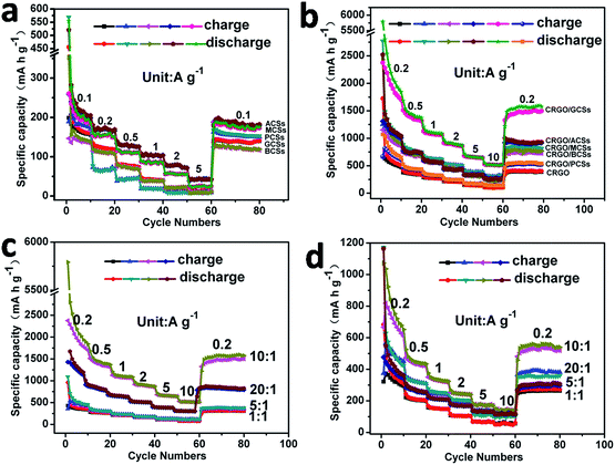
The different internal textures and surface functionalities of the CSs prepared from glucose using different acids as mineralizers may result in different properties and applications. The electrochemical properties of the GCSs and PCSs as anodes for LIBs were therefore compared. Coin cells using GCSs and PCSs (after annealing) as the anode materials were assembled. Galvanostatic charge–discharge measurements of the coin cells were conducted at current densities of 0.1, 0.2, 0.5, 1, 2 and 5 A g−1. Fig. 4a shows that, at a current density of 0.1 A g−1, the initial specific capacity of the PCS and GCS anodes reached 170 and 140 mA h g−1, respectively. This might be because there are more oxygen-containing groups on PCSs, which serve as binding sites for lithium ions and contribute to the initial specific capacity. However, once the charge–discharge current densities were increased to 0.2, 0.5, 1, 2 and 5 A g−1, the reversible specific capacities of the PCS anode decreased to 65, 45, 20, 10 and 9 mA h g−1. The reversible specific capacities of the GCS anode still remained at 130, 80, 40, 20 and 13 mA h g−1, which were higher than those of the PCS anodes. This may be a result of the higher extent of graphitization and fewer oxygen-containing groups on the GCS anodes (Fig. 4a, Table S1†). Galvanostatic charge–discharge experiments were also performed on the coin cells with MCSs, BCSs and ACSs as anodes (Fig. 4a). These CSs showed higher capacities than that PCSs, but lower capacities than the GCSs. This might be a result of the different extent of internal graphitization (Fig. 3 and S6†). Nevertheless, the electrochemical performance of the as-obtained bare CSs was not suitable for their practical application as anodes for LIBs.
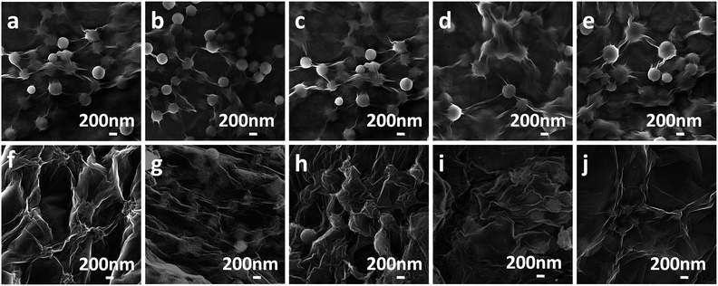
To further improve the electrochemical properties of the CSs, composites of CRGO with GCSs, MCSs, BCSs, ACSs or PCSs with different original GO to CSs ratios were prepared. Fig. 5a–e shows the GO and CSs composites without annealing; the CSs were well cladded with the GO sheets. After annealing at 900 °C for 3 h in an Ar gas flow containing 5% H2 (Fig. 5f–j), all the composites assumed 3D network structures and the CSs were further wrapped and bridged by CRGO sheets.
For comparison of the electrochemical performance of the as-obtained CRGO/CS composites used as anodes for LIBs, a series of coin cells was assembled using the as-prepared composites CRGO/GCSs, CRGO/MCSs, CRGO/BCSs, CRGO/ACSs or CRGO/PCSs as anodes. Fig. S7† shows the typical galvanostatic discharge–charge curves of the as-assembled coin cells measured at a current density of 0.2 A g−1. Fig. 4b shows the representative charge–discharge rate capabilities of the coin cells measured at current densities of 0.2, 0.5, 1, 2 5 and 10 A g−1. The anode of the composite CRGO/GCSs (original GO![[thin space (1/6-em)]](https://www.rsc.org/images/entities/char_2009.gif) :
:![[thin space (1/6-em)]](https://www.rsc.org/images/entities/char_2009.gif) GCSs = 10
GCSs = 10![[thin space (1/6-em)]](https://www.rsc.org/images/entities/char_2009.gif) :
:![[thin space (1/6-em)]](https://www.rsc.org/images/entities/char_2009.gif) 1 w/w) showed specific capacities of 2281, 1450, 1110, 900, 660 and 520 mA h g−1 at current densities of 0.2, 0.5, 1, 2, 5 and 10 A g−1, respectively, revealing the high lithium ion storage capacity and good charge–discharge rate capability. The specific capacity of the anode of composite CRGO/PCSs (original GO
1 w/w) showed specific capacities of 2281, 1450, 1110, 900, 660 and 520 mA h g−1 at current densities of 0.2, 0.5, 1, 2, 5 and 10 A g−1, respectively, revealing the high lithium ion storage capacity and good charge–discharge rate capability. The specific capacity of the anode of composite CRGO/PCSs (original GO![[thin space (1/6-em)]](https://www.rsc.org/images/entities/char_2009.gif) :
:![[thin space (1/6-em)]](https://www.rsc.org/images/entities/char_2009.gif) PCS = 10
PCS = 10![[thin space (1/6-em)]](https://www.rsc.org/images/entities/char_2009.gif) :
:![[thin space (1/6-em)]](https://www.rsc.org/images/entities/char_2009.gif) 1 w/w) could only reach 666, 460, 340, 250, 175 and 140 mA h g−1 at current densities of 0.2, 0.5, 1, 2, 5 and 10 A g−1, respectively. The CRGO/GCSs composite clearly has a better electrochemical performance as an anode for LIBs than the CRGO/PCS composite. This might be because the extent of graphitization of the GCSs is much higher than that of the PCSs (Fig. 3), which should be beneficial for the transportation and storage of both electrons and lithium ions. The composition (ratio of CRGO to CSs) of the CRGO/CSs composite may also affect the electrochemical properties. Fig. 4c and d shows the charge–discharge rate capabilities of the coin cells using the CRGO/GCS and CRGO/PCS composites prepared with original GO to CSs ratios of 1
1 w/w) could only reach 666, 460, 340, 250, 175 and 140 mA h g−1 at current densities of 0.2, 0.5, 1, 2, 5 and 10 A g−1, respectively. The CRGO/GCSs composite clearly has a better electrochemical performance as an anode for LIBs than the CRGO/PCS composite. This might be because the extent of graphitization of the GCSs is much higher than that of the PCSs (Fig. 3), which should be beneficial for the transportation and storage of both electrons and lithium ions. The composition (ratio of CRGO to CSs) of the CRGO/CSs composite may also affect the electrochemical properties. Fig. 4c and d shows the charge–discharge rate capabilities of the coin cells using the CRGO/GCS and CRGO/PCS composites prepared with original GO to CSs ratios of 1![[thin space (1/6-em)]](https://www.rsc.org/images/entities/char_2009.gif) :
:![[thin space (1/6-em)]](https://www.rsc.org/images/entities/char_2009.gif) 1, 5
1, 5![[thin space (1/6-em)]](https://www.rsc.org/images/entities/char_2009.gif) :
:![[thin space (1/6-em)]](https://www.rsc.org/images/entities/char_2009.gif) 1, 10
1, 10![[thin space (1/6-em)]](https://www.rsc.org/images/entities/char_2009.gif) :
:![[thin space (1/6-em)]](https://www.rsc.org/images/entities/char_2009.gif) 1 and 20
1 and 20![[thin space (1/6-em)]](https://www.rsc.org/images/entities/char_2009.gif) :
:![[thin space (1/6-em)]](https://www.rsc.org/images/entities/char_2009.gif) 1 as anodes. With increasing CRGO content in the composites within a reasonable range, the specific capacities and the charge–discharge rate capabilities of the CRGO/GCS and CRGO/PCS composites as anodes were clearly increased. For comparison, the electrochemical properties of coin cells with composites of CRGO/ACSs, CRGO/MCSs and CRGO/BCSs prepared with an original GO to CSs ratio of 10
1 as anodes. With increasing CRGO content in the composites within a reasonable range, the specific capacities and the charge–discharge rate capabilities of the CRGO/GCS and CRGO/PCS composites as anodes were clearly increased. For comparison, the electrochemical properties of coin cells with composites of CRGO/ACSs, CRGO/MCSs and CRGO/BCSs prepared with an original GO to CSs ratio of 10![[thin space (1/6-em)]](https://www.rsc.org/images/entities/char_2009.gif) :
:![[thin space (1/6-em)]](https://www.rsc.org/images/entities/char_2009.gif) 1 were also studied. Fig. 4b shows that, similar to the CRGO/GCS composites, when used as anodes for LIBs, the CRGO/MCS, CRGO/BCS and CRGO/ACS composites showed higher specific capacities and rate capabilities than the CRGO/PCS composite, implying that the CSs generated from glucose with organic dicarboxylic acids as mineralizers had exceptional electrochemical properties when used in the composites.
1 were also studied. Fig. 4b shows that, similar to the CRGO/GCS composites, when used as anodes for LIBs, the CRGO/MCS, CRGO/BCS and CRGO/ACS composites showed higher specific capacities and rate capabilities than the CRGO/PCS composite, implying that the CSs generated from glucose with organic dicarboxylic acids as mineralizers had exceptional electrochemical properties when used in the composites.
To understand why the CRGO/CS composites generated using organic dicarboxylic acids as mineralizers usually have better electrochemical performance as anodes for LIBs, AC impedance data for the CRGO/GCS, CRGO/PCS (original GO![[thin space (1/6-em)]](https://www.rsc.org/images/entities/char_2009.gif) :
:![[thin space (1/6-em)]](https://www.rsc.org/images/entities/char_2009.gif) CS = 10
CS = 10![[thin space (1/6-em)]](https://www.rsc.org/images/entities/char_2009.gif) :
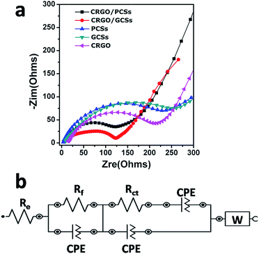
:![[thin space (1/6-em)]](https://www.rsc.org/images/entities/char_2009.gif) 1 w/w), GCS, PCS and CRGO as anodes were collected after one charge–discharge cycle. Fig. 6a shows that the diameter of the semicircle for CRGO/GCSs anode in Nyquist plots at high and medium frequencies was much smaller than those of the GCSs and CRGO anodes. Similarly, the diameter of the semicircle for the CRGO/PCS anode in the high and medium frequency range was also smaller than those of the PCS and CRGO anodes. Overall, the diameter of the semicircle for the CRGO/GCS anode was smaller than that of the CRGO/PCS anode. These results suggest that both the CRGO/GCS and CRGO/PCS anodes had lower contact and charge-transfer impedances; in contrast, the impedance of the CRGO/GCS anode was much smaller than that of the CRGO/PCS anode. The electrokinetic differences between CRGO/GCS and CRGO/PCS anodes were further investigated by modelling the AC impedance spectra based on the modified Randle's equivalent. A simple equivalent circuit model was constructed (Fig. 6b). As summarized in Table S2,† the estimated values of Rf (corresponding to the SEI film resistance) and Rct (the charge-transfer resistance) were 80.7 and 53.5 Ω, respectively, for the CRGO/GCS anode, which was significantly lower than the values for the CRGO/PCS (85.9 and 80 Ω), GCS (97.3 and 162 Ω) and CRGO (101 and 115 Ω) anodes. This might be a result of the 3D network structure of the CRGO/GCSs, in which the GCSs were clad and bridged with the CRGO sheets, which provided more spaces for lithium ions and more channels for electron and lithium ion transfers. In addition, the extent graphitization of the GCSs is much deeper than that of the PCSs, which may further improve the electrochemical properties. Therefore the CRGO/GCS anodes showed superior electrochemical properties as anodes for LIBs.
1 w/w), GCS, PCS and CRGO as anodes were collected after one charge–discharge cycle. Fig. 6a shows that the diameter of the semicircle for CRGO/GCSs anode in Nyquist plots at high and medium frequencies was much smaller than those of the GCSs and CRGO anodes. Similarly, the diameter of the semicircle for the CRGO/PCS anode in the high and medium frequency range was also smaller than those of the PCS and CRGO anodes. Overall, the diameter of the semicircle for the CRGO/GCS anode was smaller than that of the CRGO/PCS anode. These results suggest that both the CRGO/GCS and CRGO/PCS anodes had lower contact and charge-transfer impedances; in contrast, the impedance of the CRGO/GCS anode was much smaller than that of the CRGO/PCS anode. The electrokinetic differences between CRGO/GCS and CRGO/PCS anodes were further investigated by modelling the AC impedance spectra based on the modified Randle's equivalent. A simple equivalent circuit model was constructed (Fig. 6b). As summarized in Table S2,† the estimated values of Rf (corresponding to the SEI film resistance) and Rct (the charge-transfer resistance) were 80.7 and 53.5 Ω, respectively, for the CRGO/GCS anode, which was significantly lower than the values for the CRGO/PCS (85.9 and 80 Ω), GCS (97.3 and 162 Ω) and CRGO (101 and 115 Ω) anodes. This might be a result of the 3D network structure of the CRGO/GCSs, in which the GCSs were clad and bridged with the CRGO sheets, which provided more spaces for lithium ions and more channels for electron and lithium ion transfers. In addition, the extent graphitization of the GCSs is much deeper than that of the PCSs, which may further improve the electrochemical properties. Therefore the CRGO/GCS anodes showed superior electrochemical properties as anodes for LIBs.
Conclusion
The effects of different acids on the formation of CSs through the hydrothermal reaction of glucose were systematically studied. It was demonstrated that monodispersed CSs can be synthesized by the hydrothermal reaction of glucose using organic dicarboxylic acids (e.g. malonic acid, butanedioic acid, glutaric acid and adipic acid) as catalysts. However, under the same hydrothermal reaction conditions, the CSs prepared with inorganic acids, such as sulfuric acid, hydrochloric acid and nitric acid, were severely cross-linked, except with phosphoric acid. It was also found that the CSs generated with organic dicarboxylic acids showed a higher extent of graphitization than those formed using inorganic acids as catalysts under the same thermal annealing treatment. More importantly, when used as anodes for LIBs, both bare CSs and CRGO/CS composites prepared using organic dicarboxylic acids as catalysts showed larger reversible specific capacities and higher rate capabilities than those prepared with inorganic acids. Consequently, it may be speculated that organic dicarboxylic acids are more suitable for use as catalysts for the preparation of CSs through the hydrothermal reaction of glucose than inorganic acids. This should be helpful in further studies of the hydrothermal carbonization of biomass materials.Acknowledgements
We thank the National “973 Program” of China (No. 2014CB260411), the National Science foundation of China (No. 11374205) and the National “863” Program of China (No. 2012AA022603) for financial support of this work.References
- A. A. Deshmukh, S. D. Mhlanga and N. J. Coville, Mater. Sci. Eng., R, 2010, 70, 1–28 CrossRef.
- Z. Yi, Y. Liang, X. Lei, C. Wang and J. Sun, Mater. Lett., 2007, 61, 4199–4203 CrossRef CAS.
- X. Sun and Y. Li, Angew. Chem., Int. Ed., 2004, 43, 597–601 CrossRef PubMed.
- R. Alcántara, P. Lavela, G. F. Ortiz and J. L. Tirado, Electrochem. Solid-State Lett., 2005, 8, A222–A225 CrossRef.
- Q. Li, R. Jiang, Y. Dou, Z. Wu, T. Huang, D. Feng, J. Yang, A. Yu and D. Zhao, Carbon, 2011, 49, 1248–1257 CrossRef CAS.
- Z. Lei, N. Christov and X. S. Zhao, Energy Environ. Sci., 2011, 4, 1866–1873 CAS.
- Y. Zhu, T. Ikoma, N. Hanagata and S. Kaskel, Small, 2010, 6, 471–478 CrossRef CAS PubMed.
- R. Demir-Cakan, P. Makowski, M. Antonietti, F. Goettmann and M.-M. Titirici, Catal. Today, 2010, 150, 115–118 CrossRef CAS.
- Z. Wen, Q. Wang, Q. Zhang and J. Li, Electrochem. Commun., 2007, 9, 1867–1872 CrossRef CAS.
- Q. Wang, X. Liang, W. Qiao, C. Liu, X. Liu, L. Zhan and L. Ling, Fuel Process. Technol., 2009, 90, 381–387 CrossRef CAS.
- Z. Lei, Z. Chen and X. S. Zhao, J. Phys. Chem. C, 2010, 114, 19867–19874 CAS.
- C. Huang, C. Hsu, P. Kuo, C. Hsieh and H. Teng, Carbon, 2011, 49, 895–903 CrossRef CAS.
- Y. Yang, R. Pang, X. Zhou, Y. Zhang, H. Wu and S. Guo, J. Mater. Chem., 2012, 22, 23194–23200 RSC.
- J. Qiu, Y. Li, Y. Wang, C. Liang, T. Wang and D. Wang, Carbon, 2003, 41, 767–772 CrossRef CAS.
- H. Liu, W. Cui, L. Jin, C. Wang and Y. Xia, J. Mater. Chem., 2009, 19, 3661–3667 RSC.
- R. D. Cakan, M.-M. Titirici, M. Antonietti, G. Cui, J. Maier and Y.-S. Hu, Chem. Commun., 2008, 3759–3761 RSC.
- Z. Zhang, Y. Liu, X. Cao and P. Liang, J. Radioanal. Nucl. Chem., 2013, 295, 1775–1782 CrossRef CAS.
- K. Pan, H. Ming, Y. Liu and Z. Kang, New J. Chem., 2012, 36, 113–118 RSC.
- C. Chen, X. Sun, X. Jiang, D. Niu, A. Yu, Z. Liu and J. Li, Nanoscale Res. Lett., 2009, 4, 971–976 CrossRef CAS PubMed.
- S. Yang, X. Feng, S. Ivanovici and K. Mullen, Angew. Chem., Int. Ed., 2010, 49, 8408–8411 CrossRef CAS PubMed.
- A. van Blaaderen and A. Vrij, Langmuir, 1992, 8, 2921–2931 CrossRef CAS.
- M. Li, W. Li and S. Liu, Carbohydr. Res., 2011, 346, 999–1004 CrossRef CAS PubMed.
- S. Zhao, C. Wang, M. Chen, Z. Shi and N. Liu, New Carbon Materials, 2010, 25, 438–443 CrossRef CAS.
- S. Zheng, T. Zhu, Y. Chen, C. Lin, Y. Chen and H. Guo, J. Nanopart. Res., 2014, 16, 2649 CrossRef.
- R. Demir-Cakan, N. Baccile, M. Antonietti and M.-M. Titirici, Chem. Mater., 2009, 21, 484–490 CrossRef CAS.
- H. Xiong, M. Moyo, M. A. M. Motchelaho, L. L. Jewell and N. J. Coville, Appl. Catal., A, 2010, 388, 168–178 CrossRef CAS.
- X. Zhou, J. Zhang, H. Wu, H. Yang, J. Zhang and S. Guo, J. Phys. Chem. C, 2011, 115, 11957–11961 CAS.
- Q. Wang, H. Li, L. Chen and X. Huang, Solid State Ionics, 2002, 152, 43–50 CrossRef.
- N. Baccile, G. Laurent, F. Babonneau, F. Fayon, M.-M. Titirici and M. Antonietti, J. Phys. Chem. C, 2009, 113, 9644–9654 CAS.
- Y. Shin, L. Wang, I.-T. Bae, B. W. Arey and G. J. Exarhos, J. Phys. Chem. C, 2008, 112, 14236–14240 CAS.
Footnote |
| † Electronic supplementary information (ESI) available. See DOI: 10.1039/c5ra27329c |
| This journal is © The Royal Society of Chemistry 2016 |

