CO2 methanation over a Ni based ordered mesoporous catalyst for the production of synthetic natural gas
Leilei Xu*abc,
Fagen Wange,
Mindong Chen*a,
Jian Zhangb,
Kaidi Yuand,
Liangjun Wangd,
Kai Wucf,
Guoqin Xubce and
Wei Chenbcde
aSchool of Environmental Science and Engineering, Nanjing University of Information Science & Technology, Jiangsu Key Laboratory of Atmospheric Environment Monitoring and Pollution Control, Collaborative Innovation Center of Atmospheric Environment and Equipment Technology, 210044, Nanjing, China. E-mail: chenmdnuist@163.com; Tel: +86-25-58731089
bDepartment of Chemistry, National University of Singapore, 3 Science Drive 3, 117543, Singapore. E-mail: leileixu88@gmail.com; Tel: +65-96382289
cSingapore-Peking University Research Center for a Sustainable Low-Carbon Future, 1 CREATE Way, #15-01, CREATE Tower, Singapore 138602, Singapore
dDepartment of Physics, National University of Singapore, 2 Science Drive 3, 117551, Singapore
eNational University of Singapore (Suzhou) Research Institute, Suzhou, China
fCollege of Chemistry and Molecular Engineering, Peking University, Beijing 100871, China
First published on 14th March 2016
Abstract
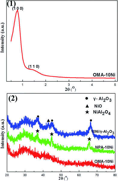
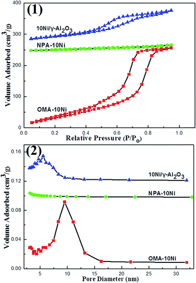
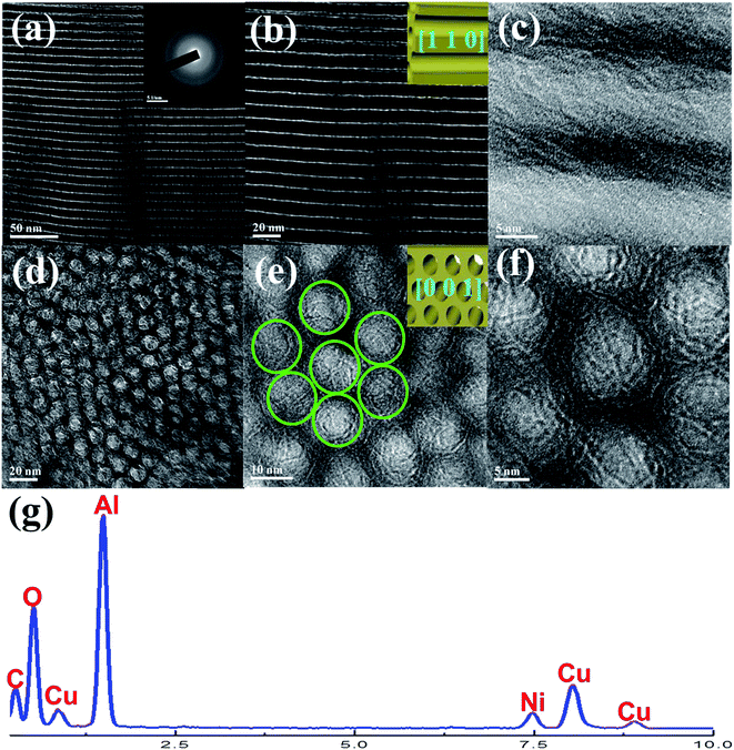
Ni based catalysts have been considered as ideal candidates for the CO2 methanation reaction to generate synthetic natural gas owing to its high activity and low cost. In the present manuscript, we described a kind of ordered mesoporous NiO–Al2O3 composite metal oxide, fabricated by a one-step evaporation induced self-assembly (EISA) strategy, which was utilized as the catalyst for CO2 methanation. The obtained material was characterized by XRD, N2 adsorption–desorption, TEM-EDS, H2-TPR, and XPS techniques. The mesoporous catalyst with a large specific surface area (232.8 m2 g−1), big pore volume (0.43 cm3 g−1), tunable pore diameter (9.5 nm), strong metal–mesoporous framework interaction, and outstanding thermal stability (up to 800 °C) had a better catalytic performance than traditional non-mesoporous and supported reference catalysts. The ordered interconnected mesoporous network was beneficial to the mass diffusion of the gaseous reactants and enhanced the catalytic performance by providing sufficient accessible metallic active centers for the gaseous reactants. Besides, the Ni metallic nanoparticles could be stabilized via the space confinement effect of the mesoporous framework, finally reinforcing the catalytic stability. Generally, the presently reported ordered mesoporous NiO–Al2O3 composite oxide promises to be a potential catalyst candidate for CO2 methanation.
1. Introduction
Due to the rapid development of modern industry, large amounts of fossil fuels have been consumed.1 As a result, the atmospheric concentration of carbon dioxide, well-known as the most important greenhouse gas, has continuously increased during the past decades.1,2 The drastic increase in CO2 concentration is recognized as the main cause for the global warming. There has been increasing pressure as well as demand around the world to effectively control and reduce CO2 emissions. Therefore, CO2 capture and conversion have attracted a lot of interest in recent decades.1,3 It is very urgent for academia and industry to develop efficient carbon capture and utilization techniques.4 Recycling CO2 known as the cheapest carbon source for chemicals and fuels could be considered as a sustainable way, which can indeed lead to less consumption of carbon-based fossil resources without producing more CO2 from the whole system.2 In recent years, numerous of different technological routes have been tried to reduce CO2 in atmosphere. In case the cheap hydrogen source is available via renewable and sustainable ways, such as photocatalysis, biomass, etc., the hydrogenation of CO2 could be considered as a promising option for CO2 capture and storage.5,6 Fuels and chemicals synthesized from CO2 hydrogenation are mainly methane, methanol, dimethyl ether, light hydrocarbon, gasoline, formic acid, and other oxygenates.7–14Compared with the production of hydrocarbon and alcohols, the production of methane via CO2 methanation, also called Sabatier reaction, is more advantageous in terms of thermodynamics due to its strong exothermic feature (CO2 (g) + 4H2 (g) = CH4 (g) + 2H2O (g), ΔH298 = −165.0 kJ mol−1, ΔG298 = −113.2 kJ mol−1).15,16 Besides, the natural gas has been considered as a potential energy source because of its clean feature.6 Therefore, conversion of CO2 to methane via methanation process not only enhances the reduction of greenhouse gas emissions, but it also enables development of new carbon sources for new ways of utilizing CO2. As an important catalytic process, it has a wide range of applications, such as the production of substitute natural gas from the flue gas, the purification of synthesis gas for the synthesis of ammonia, etc.2 Although the CO2 methanation is a thermodynamically favorable process, the reduction of the fully oxidized carbon to methane at low temperature is still a challenging topic. Because this process is an eight-electron process with significant kinetic limitations, it requires a catalyst to achieve acceptable CO2 conversion rate and CH4 selectivity.2,17 Extensive studies have been conducted on the hydrogenation of CO2 to methane. Various catalyst systems have been tested and investigated for this reaction. It has been widely believed that most of the group VIII metals (such as Ni, Co, Pd, Ru, Rh, etc.) are active catalysts for this process.18–26 But the Ni based catalysts remain the most widely investigated catalysts due to their high activity and low price.5,27–30
The effect of the catalyst support on catalytic activity, selectivity, and stability has been widely investigated over Ni based catalysts. The support usually has significant influences on dispersion of active site and diffusion of the feedstock gases, finally affecting the catalytic properties.5,17 As for the CO2 methanation itself, it is often accompanied by hot spot in the catalyst bed due to the intensively exothermic feature of this reaction.15 The actual temperature of the catalyst bed is usually much higher than the preset reaction furnace temperature. Therefore, the severe thermal agglomeration of the Ni metallic active centers is also an important concern for this process due to its inherent low thermal agglomeration temperature.31,32 As a result, designing and fabricating Ni based catalyst with high dispersion and sintering resistance for the metallic active sites is of great necessity. To achieve these goals, a series of silica based mesoporous molecular sieves incorporated with metal active centers, such as Ni-MCM-41, Fe-KIT-6, Co-KIT-6, etc., have been designed and fabricated via a direct hydrothermal synthesis approach. In these materials, the metallic active centers are in situ embedded among the framework via the coordination action with the silica framework.17,22,33 Besides, the Ni metallic active sites are often grafted onto the mesoporous channel (such as SBA-15) to form –O–Ni–O–Si–O– structure using unique preparation strategy.34 In contrast with traditional supported catalysts, the metal–support interaction became much stronger and the dispersion of metal species became greatly better. As a result, these mesoporous catalysts perform more excellent catalytic activities and stabilities because of their ordered mesoporous structure, large specific surface area, tailorable pore size, high Ni dispersion, and interconnected porous networks, promising the improved diffusion of the gaseous feedstock and high utilization efficiency of the metallic active components.33 However, the intrinsic hydrothermal instability of these silica based mesoporous molecular sieve usually causes the collapse of the mesoporous framework, thus causing the deactivation of the catalyst.35 Therefore, it is necessary for the researchers to prepare ordered mesoporous materials with high Ni dispersion as well as outstanding thermal stability. Ordered mesoporous metal oxides with good thermal stability will be a series of potential candidates.36 However, the difficulty for synthesizing them is much higher than silica based mesoporous materials due to the easy hydrolysis characteristics of metal cations, especially in the aqueous solution. It is greatly difficult to control the balance between hydrolysis and polymerization of the metallic ions during the self-assembly process of the ordered mesoporous structure.37–39 Therefore, it is of great necessity to fabricate Ni based ordered mesoporous metal oxide materials with high thermal stability and well-dispersed metal species.
Herein, we present a simple and reproducible route to fabricate ordered mesoporous NiO–Al2O3 composite metal oxide with high specific surface area (232.8 m2 g−1), large pore volume (0.43 cm3 g−1), uniform pore size (9.5 nm), and outstanding thermal stability (800 °C) by improved one-step evaporation induced self-assembly (EISA) method in absolute ethanol system using nitric acid as modifier. The balance between metallic ions hydrolysis and polymerization during the self-assembly process could be effectively controlled. The prepared material was utilized as catalyst for CO2 methanation reaction. Compared with supported catalyst, the Ni species in current material were homogeneously embedded among the matrix of mesoporous framework, which could effectively inhibit the thermal agglomeration of the Ni nanoparticles via the space confinement effect of the material during the process of CO2 methanation. Furthermore, the ordered mesoporous catalyst with uniform pore size can promise the facile access to the exposed metallic active sites for the gaseous feedstock, which would be beneficial to the diffusion of the reactant gases and accelerating the kinetic process. Therefore, the present ordered mesoporous NiO–Al2O3 composite metal oxide will promise an effective catalyst candidate for CO2 methanation reaction.
2. Experimental
2.1. Method for fabricating ordered mesoporous NiO–Al2O3 composite metal oxide material
Ordered mesoporous NiO–Al2O3 composite metal oxide via one-step evaporation induced self-assemble (EISA) strategy by improving pioneer literatures.40,41 Firstly, approximately 1.0 g (EO)20(PO)70(EO)20 triblock copolymer (Pluronic P123, Mn = 5800, Sigma-Aldrich) was poured into 20.0 mL absolute ethanol with vigorous stirring to obtain a clear solution. Then, 1.6 mL of 67.0 wt% concentrated nitric acid, 10 mmol aluminum isopropoxide (98+%, Sigma-Aldrich), and 1 mmol Ni(NO3)2·6H2O (Sigma-Aldrich) were sequentially added with vigorous stirring for at least 5 h to obtain a homogeneous green solution. The solution was poured into a Petri dish to evaporate the solvent in a temperature and humidity controlled chamber at 60 °C with 50% relative humidity for 48 h. Finally, the resulting green xerogel was calcined in a muffle furnace by slowly increasing temperature from room temperature to 700 °C with a heating rate of 1 °C min−1 and maintaining at 700 °C for 5 h in air. The obtained ordered mesoporous NiO–Al2O3 material was denoted as OMA–10Ni, where “10” stood for the theoretical value of Ni/Al molar ratio percentage (nNi/nAl × 100%, nNi = 1 mmol, nAl = 10 mmol).In order to investigate the roles of ordered mesostructured and space confinement effect in promoting catalytic property, NiO–Al2O3 composite metal oxide without ordered mesostructure and Ni/γ-Al2O3 supported reference catalysts were also prepared. The non-mesoporous materials were denoted as NPA–10Ni. The preparation process of NPA–10Ni was similar to that of OMA–10Ni, only without the addition of Pluronic P123 template. Besides, Ni/γ-Al2O3 supported catalyst with the identical Ni/Al molar percentage to OMA–10Ni was prepared via incipient wetness impregnation method using Ni(NO3)2·6H2O (Sigma-Aldrich) as the precursor of nickel. After impregnation, the catalyst precursors were dried in a 60 °C oven for overnight and calcined at 700 °C for 5 h, denoted as 10Ni/γ-Al2O3.
2.2. Catalyst characterizations
X-ray diffraction (XRD) patterns were recorded on an X'pert Pro multipurpose diffractometer (PANalytical, Inc., Netherlands) with Ni-filtered Cu Kα radiation (0.15046 nm). The N2 adsorption and desorption analysis were measured using NOVA 2200e (Quantachrome, US) at −196 °C. The inductive coupled plasma atomic emission spectrometer (ICP-AES) was determined on Optima 7300DV (Perkin Elmer, US) to get the actual Ni/Al ratios of the samples. Transmission electron microscopy (TEM) images, selected area electron diffraction (SAED), and energy-dispersed spectroscopy (EDS) measurements were performed on a JEOL 2010F microscope (Japan) under a working voltage of 200 kV. X-ray photoelectron spectroscopy (XPS) analyses of the catalysts were performed on a VG ESCALAB 210 (Thermo Scientific, US) spectrometer. H2 temperature programmed reduction (H2-TPR) measurements for the as-prepared catalysts (100 mg) were performed on a ChemBET Pulsar TPR/TPD (Quantachrome, US) utilizing 5 mol% H2/He steam (80 mL min−1) as reducing agent and the hydrogen consumption was recorded using TCD detector.2.3. Catalytic properties measurement
The carbon dioxide methanation reaction was performed in a vertical fixed bed quartz reactor at atmospheric pressure. The temperature of the reaction bed was determined by a coaxial thermocouple, which protected by a small quartz thermocouple well located at the center of catalyst bed. The flow rates of reactant gases were precisely regulated by calibrated mass flow controllers (Beijing Sevenstar Electronics Co., Ltd., China). For each test, 100 mg catalyst was loaded on the quartz fixed-bed reactor. Prior to the reaction, the catalyst was in situ reduced in a mixed flow of H2 and N2 (10/20 mL min−1) with a heating rate of 1.5 °C min−1 rate to 800 °C, and maintained at 800 °C for 120 min. Then, the reaction gases (H2/CO2 = 4, without dilution) were introduced into the reactor and the gaseous products were analyzed on line by the gas chromatograph (Agilent 7890B) equipped with automatic six-port valve injector.There was no C2+ hydrocarbon detected by the GC FID detector during the catalytic reaction. Therefore, the CO2 conversion (CCO2), CH4 selectivity (SCH4), and CO selectivity (SCO) were calculated according to the following formulas, where the Fin, Fout stood for the gas flow rates of different gases (CO2, CH4, or CO) passing into and out of the reactor, respectively.
| CCO2 = (Fin,CO2 − Fout,CO2)/Fin,CO2 × 100% | (1) |
| SCH4 = Fout,CH4/(Fout,CH4 + Fout,CO) × 100% | (2) |
| SCO = Fout,CO/(Fout,CH4 + Fout,CO) × 100% | (3) |
3. Results and discussion
3.1. Characterizations of the catalysts
| Samples | SBETa (m2 g−1) | VBJHb (cm3 g−1) | APDc (nm) | d(1 0 0)e (nm) | WTf (nm) | Ni/AlTVg | Ni/AlAVh | Isotherm type |
|---|---|---|---|---|---|---|---|---|
a SBET stands for the specific area calculated based on Brunauer–Emmett–Teller theory.b VBJH stands for the pore volume calculated based on Barrett–Joyner–Halenda theory.c APD stands for average pore diameter.d SP stands for 50 h spent catalyst.e d(1 0 0) stands for the d-spacing of the (1 0 0) direction calculated by the Bragg's law: d = nλ/2![[thin space (1/6-em)]](https://www.rsc.org/images/entities/char_2009.gif) sin sin![[thin space (1/6-em)]](https://www.rsc.org/images/entities/char_2009.gif) θ, where λ is the wavelength of the X-ray wave (0.15406 nm).f WT stands for the wall thickness (calculated by θ, where λ is the wavelength of the X-ray wave (0.15406 nm).f WT stands for the wall thickness (calculated by  – pore diameter).g Ni/AlTV stands for the theoretical value of Ni/Al ratio.h Ni/AlAV stands for the actual value of the Ni/Al ratio based on the ICP-AES result. – pore diameter).g Ni/AlTV stands for the theoretical value of Ni/Al ratio.h Ni/AlAV stands for the actual value of the Ni/Al ratio based on the ICP-AES result. |
||||||||
| OMA–10Ni | 233.0 | 0.43 | 9.5 | 11.3 | 3.5 | 0.10 | 0.097 | IV H1 |
| NPA–10Ni | 41.7 | 0.10 | — | — | — | 0.10 | 0.099 | — |
| 10Ni/Al2O3 | 158.0 | 0.17 | 5.5 | — | — | 0.10 | 0.095 | IV H2 |
| SPd OMA–10Ni | 139.0 | 0.27 | 8.5 | 10.6 | 3.7 | 0.10 | 0.098 | IV H1 |
| SP NPA–10Ni | 22.1 | 0.03 | — | — | — | 0.10 | 0.097 | IV H3 |
| SP 10Ni/Al2O3 | 107.0 | 0.11 | 5.0 | — | — | 0.10 | 0.096 | IV H2 |
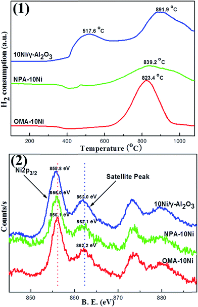
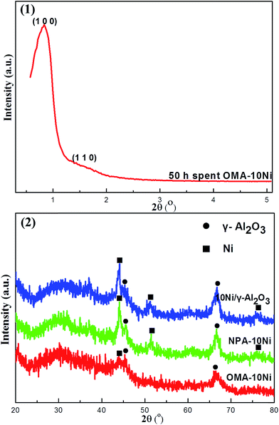
XPS was used to determine the chemical state of the Ni species over the catalyst surface. As shown in Fig. 4(2), both OMA–10Ni and NPA–10Ni displayed obvious Ni 2p3/2 peaks around 856.0 eV and satellite peaks around 862.0 eV, which were the characteristic peaks for the present of NiAl2O4 spinel species based on previous literatures.44,45 This indicated that the NiAl2O4 species existed over the surface of these two samples. For the NPA–10Ni, the presence of NiAl2O4 species had been verified by its XRD pattern in Fig. 1(2). For the OMA–10Ni, though it did not exhibit any pronounced XRD peak related with NiAl2O4 phase, the current XPS result confirmed the presence of NiAl2O4 species over the material surface. This explained the phenomenon why the H2-TPR profile of NPA–10Ni presented reduction peak at as high temperature (823.4 °C) as NPA–10Ni (839.2 °C). As for 10Ni/γ-Al2O3 supported catalyst, its Ni 2p3/2 peak is centered at 855.8 eV, which was a little lower than 856.0 eV. The shift to lower binding energy range could be attributed to the surface NiO species, which had also given evident NiO phase diffraction peaks in the XRD pattern of 10Ni/γ-Al2O3 (see Fig. 1(2)).
3.2. Catalyst performances towards CO2 methanation
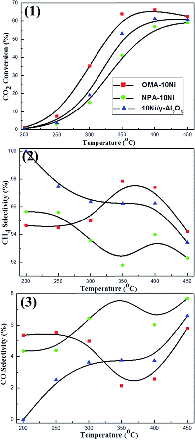
![[thin space (1/6-em)]](https://www.rsc.org/images/entities/char_2009.gif) 000 mL g−1 h−1, 1 atm. As shown in the Fig. 5(1), the conversion of CO2 over OMA–10Ni ordered mesoporous catalyst was much higher than those over NPA–10Ni and 10Ni/γ-Al2O3 catalysts in the temperature region (200–450 °C) investigated. This demonstrated that the ordered mesostructure could significantly promote the catalytic activity. Typically, the OMA–10Ni could provide more accessible Ni active centers for the gaseous reactants than NPA–10Ni and 10Ni/γ-Al2O3 due to its larger surface area and unblocked mesoporous channel, which made the mass diffusion of feedstock gases towards metallic active centers become easier. As for the CH4 selectivity over different catalysts, it could be observed in Fig. 5(2) that the OMA–10Ni performed the highest CH4 selectivity at 350 °C; however, the NPA–10Ni and 10Ni/γ-Al2O3 performed their highest CH4 selectivity at low temperature around 200 °C. Besides, as shown in Fig. 5(3), NPA–10Ni and 10Ni/γ-Al2O3 behaved much higher CO selectivity than OMA–10Ni, especially when the reaction temperatures were higher than 350 °C. For the generation of the CO over these Ni based catalysts, it may be related with the reactant intermediate during the process of methane formation. Although the reaction mechanism of the CO2 methanation had been intensively investigated, there were still some arguments on the nature of the intermediate compounds during the formation of methane.15 The main discrepancy was whether the reaction went through the formation of CO intermediate.19,46,47 It had been previously reported that the formation of methane from CO2 may experience the process converting CO2 to CO intermediate stage and subsequent reaction mechanism for CO methanation.5,47 But there was still a viewpoint believing the direct hydrogenation of CO2 to methane without forming a CO intermediate.19 For the results of our current research, the CO side product always existed at different reaction temperatures. This suggested that the reaction mechanism might experience the CO intermediate state. For the Ni based catalyst, the previous literatures indicated that the process of CO2 methanation reaction on catalyst surface might be carried out as following steps.5,48 Generally, CO2 was dissociated over the catalyst support into carbon species (COads) and oxygen species (Oads); the H2 was activated on the Ni surface to form the Hads. Finally, the COads would react with the Hads species to generate CH4 over the Ni surface.48,49 If the thermal agglomeration of the metallic Ni active centers took place, its H2 activation ability would decrease. As a result, the selectivity of CH4 would decrease due to lack of the Hads source.
000 mL g−1 h−1, 1 atm. As shown in the Fig. 5(1), the conversion of CO2 over OMA–10Ni ordered mesoporous catalyst was much higher than those over NPA–10Ni and 10Ni/γ-Al2O3 catalysts in the temperature region (200–450 °C) investigated. This demonstrated that the ordered mesostructure could significantly promote the catalytic activity. Typically, the OMA–10Ni could provide more accessible Ni active centers for the gaseous reactants than NPA–10Ni and 10Ni/γ-Al2O3 due to its larger surface area and unblocked mesoporous channel, which made the mass diffusion of feedstock gases towards metallic active centers become easier. As for the CH4 selectivity over different catalysts, it could be observed in Fig. 5(2) that the OMA–10Ni performed the highest CH4 selectivity at 350 °C; however, the NPA–10Ni and 10Ni/γ-Al2O3 performed their highest CH4 selectivity at low temperature around 200 °C. Besides, as shown in Fig. 5(3), NPA–10Ni and 10Ni/γ-Al2O3 behaved much higher CO selectivity than OMA–10Ni, especially when the reaction temperatures were higher than 350 °C. For the generation of the CO over these Ni based catalysts, it may be related with the reactant intermediate during the process of methane formation. Although the reaction mechanism of the CO2 methanation had been intensively investigated, there were still some arguments on the nature of the intermediate compounds during the formation of methane.15 The main discrepancy was whether the reaction went through the formation of CO intermediate.19,46,47 It had been previously reported that the formation of methane from CO2 may experience the process converting CO2 to CO intermediate stage and subsequent reaction mechanism for CO methanation.5,47 But there was still a viewpoint believing the direct hydrogenation of CO2 to methane without forming a CO intermediate.19 For the results of our current research, the CO side product always existed at different reaction temperatures. This suggested that the reaction mechanism might experience the CO intermediate state. For the Ni based catalyst, the previous literatures indicated that the process of CO2 methanation reaction on catalyst surface might be carried out as following steps.5,48 Generally, CO2 was dissociated over the catalyst support into carbon species (COads) and oxygen species (Oads); the H2 was activated on the Ni surface to form the Hads. Finally, the COads would react with the Hads species to generate CH4 over the Ni surface.48,49 If the thermal agglomeration of the metallic Ni active centers took place, its H2 activation ability would decrease. As a result, the selectivity of CH4 would decrease due to lack of the Hads source.
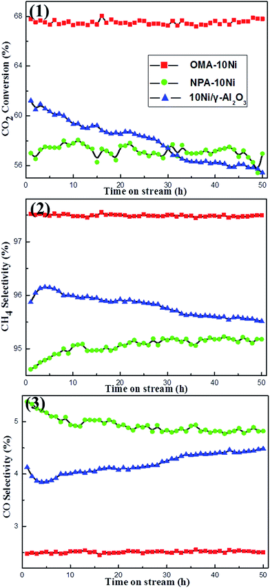
![[thin space (1/6-em)]](https://www.rsc.org/images/entities/char_2009.gif) 000 mL g−1 h−1, 1 atm) over above-mentioned catalysts. Prior to standard catalytic test, blank test was firstly carried out in a reaction tube only filled with quartz wool, performing neglected activity. As shown in the Fig. 7(1), OMA–10Ni catalyst with ordered mesoporous structure performed higher catalytic activity as well as more excellent catalytic stability than both NPA–10Ni and 10Ni/γ-Al2O3 catalysts during the whole 50 h stability test. Compared with NPA–10Ni with no mesoporous structure, the OMA–10Ni catalysts could provide more effectively accessible Ni active centers to the gaseous reactants due to its large surface area, big pore volume, and unblocked mesoporous channel, which accounted for its much higher catalytic activity. As a comparison, the 10Ni/γ-Al2O3 supported catalyst suffered continuous decline in CO2 conversion from 61.2% to 55.3%. The deactivation of the 10Ni/γ-Al2O3 supported catalyst could be derived from the thermal agglomeration of the metallic Ni active sites due to its weak interaction with the γ-Al2O3 support. Besides, it could be observed in Fig. 7(2) and (3) that OMA–10Ni behaved both higher CH4 selectivity and lower CO selectivity than NPA–10Ni and 10Ni/γ-Al2O3 catalysts during the whole 50 h stability test at 300 °C. As for NPA–10Ni, its CH4 selectivity exhibited some increase in the initial 10 h and then kept steady in the subsequent 40 h long-term stability test. However, for 10Ni/γ-Al2O3, its CH4 selectivity increased in initial 3 h and then suffered gradual decline in subsequent 47 h time on stream. This might be caused by the thermal sintering of the metallic Ni nanoparticles, which would decrease the H2 activation capacity and increase the CO selectivity.
000 mL g−1 h−1, 1 atm) over above-mentioned catalysts. Prior to standard catalytic test, blank test was firstly carried out in a reaction tube only filled with quartz wool, performing neglected activity. As shown in the Fig. 7(1), OMA–10Ni catalyst with ordered mesoporous structure performed higher catalytic activity as well as more excellent catalytic stability than both NPA–10Ni and 10Ni/γ-Al2O3 catalysts during the whole 50 h stability test. Compared with NPA–10Ni with no mesoporous structure, the OMA–10Ni catalysts could provide more effectively accessible Ni active centers to the gaseous reactants due to its large surface area, big pore volume, and unblocked mesoporous channel, which accounted for its much higher catalytic activity. As a comparison, the 10Ni/γ-Al2O3 supported catalyst suffered continuous decline in CO2 conversion from 61.2% to 55.3%. The deactivation of the 10Ni/γ-Al2O3 supported catalyst could be derived from the thermal agglomeration of the metallic Ni active sites due to its weak interaction with the γ-Al2O3 support. Besides, it could be observed in Fig. 7(2) and (3) that OMA–10Ni behaved both higher CH4 selectivity and lower CO selectivity than NPA–10Ni and 10Ni/γ-Al2O3 catalysts during the whole 50 h stability test at 300 °C. As for NPA–10Ni, its CH4 selectivity exhibited some increase in the initial 10 h and then kept steady in the subsequent 40 h long-term stability test. However, for 10Ni/γ-Al2O3, its CH4 selectivity increased in initial 3 h and then suffered gradual decline in subsequent 47 h time on stream. This might be caused by the thermal sintering of the metallic Ni nanoparticles, which would decrease the H2 activation capacity and increase the CO selectivity.
Generally, the above-mentioned results indicated that OMA–10Ni catalyst performed higher catalytic activity, CH4 selectivity, and better stability for CO2 methanation than other reference catalysts under specific reaction conditions due to its excellent structural property, highly dispersed Ni active sites, and the space confinement effect of mesoporous framework. But it could be noticeable that the highest conversion of the CO2 was obtained around 400 °C, which also had much room for improvement to realize the activation of CO2 at low temperature. Recently, M. Wei et al. reported a series of alkaline-assisted Ni nanocatalysts with layered double hydroxides (LDHs) structure for CO2 methanation, which could achieved near-equilibrium CO2 conversion at 250 °C (GHSV = 2400 h−1).50 Although its gas velocity was relatively small, it could activate the CO2 at relatively low temperature. The temperature for CO2 activation over alkaline-assisted Ni nanocatalyst was lower than that over OMA–10Ni. The reason for this phenomenon might be derived from the presence of MgO basic site, which served as the active center for CO2 activation to generate carbonate or hydrocarbonate. They found that the cooperative effect occurring at the Ni/MgO interface accounted for its excellent low-temperature activation for CO2 activation. This research would give us some inspiration for the future research in this field. For the current ordered mesoporous NiO–Al2O3 composite oxide catalyst, the incorporation of some basic sites (such as Mg, Ca or La) into the mesoporous framework might be able to greatly decrease the activation temperature for CO2.
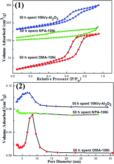
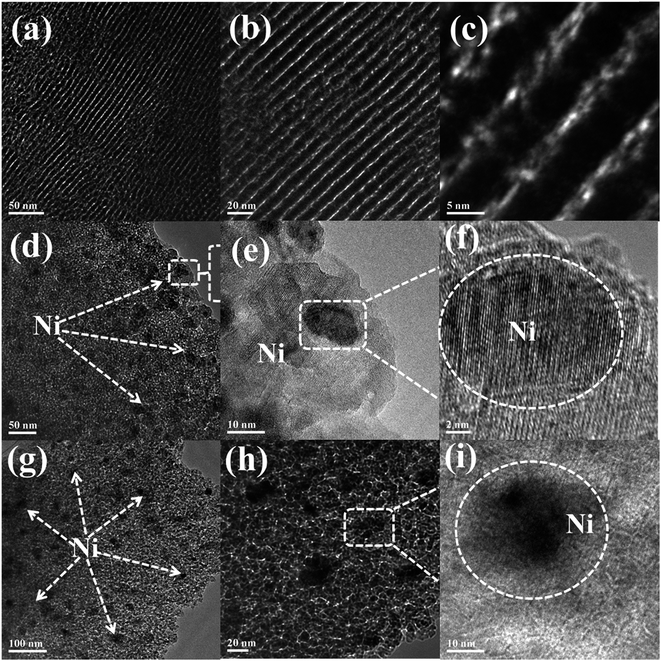
3.3. Characterization of the 50 h long-term stability tested catalysts
4. Conclusion
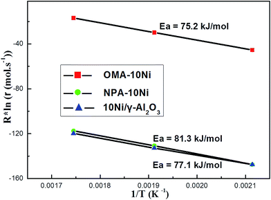
In summary, the ordered mesoporous NiO–Al2O3 composite metal oxide with large specific surface area (232.8 m2 g−1), big pore volume (0.43 cm3 g−1), uniform pore diameter (9.5 nm), and good thermal stability (800 °C) prepared by improved one-step evaporation induced self-assembly process was utilized as the catalyst for CO2 methanation. The mesoporous catalyst showed better catalytic activity, stability, and higher CH4 selectivity than NPA–10Ni and 10Ni/γ-Al2O3 reference catalysts. Based on performance-structure dependent results and characterization studies by different characterization techniques, it could be concluded that the outstanding textural properties of OMA–10Ni was the main contributor to significant enhancement in catalytic activity and decrease in kinetic apparent activation energy of CO2, which could provide enough accessible active sites for the gaseous feed gases and increase the molecular collision frequency. The ordered mesoporous structure of OMA–10Ni could stabilize the Ni nanoparticles via the space confinement effect of the mesoporous framework. The strong interaction between the Ni species and mesoporous framework had been formed, which could effectively inhibit Ni nanoparticles from seriously thermal sintering. The present results demonstrated that the herein reported ordered mesoporous NiO–Al2O3 composite metal oxide material could be considered as a promising catalyst for CO2 methanation reaction.Acknowledgements
The authors sincerely acknowledge the financial support from National Natural Science Foundation of China (Grant No. 21503113, Grant No. 21577065, Grant No. 21503142), a Project Funded by the Priority Academic Program Development of Jiangsu Higher Education Institutions, Singapore MOE grant R143-000-542-112, Singapore National Research Foundation CREATE-SPURc program R-143-001-205-592, and Jiangsu Province Government Research Platform Grant and NUSRI Seed Fund.References
- C. Song, Catal. Today, 2006, 115, 2–32 CrossRef CAS.
- W. Wei and G. Jinlong, Front. Chem. Sci. Eng., 2011, 5, 2–10 CrossRef.
- M. Aresta, Carbon dioxide as chemical feedstock, John Wiley & Sons, 2010 Search PubMed.
- M. Mikkelsen, M. Jørgensen and F. C. Krebs, Energy Environ. Sci., 2010, 3, 43–81 CAS.
- W. Zhen, B. Li, G. Lu and J. Ma, Chem. Commun., 2015, 51, 1728–1731 RSC.
- J. Ren, X. Qin, J. Z. Yang, Z. F. Qin, H. L. Guo, J. Y. Lin and Z. Li, Fuel Process. Technol., 2015, 137, 204–211 CrossRef CAS.
- A. T. Aguayo, J. Ereña, I. Sierra, M. Olazar and J. Bilbao, Catal. Today, 2005, 106, 265–270 CrossRef CAS.
- J. Ma, N. Sun, X. Zhang, N. Zhao, F. Xiao, W. Wei and Y. Sun, Catal. Today, 2009, 148, 221–231 CrossRef CAS.
- H. Zhan, F. Li, P. Gao, N. Zhao, F. Xiao, W. Wei, L. Zhong and Y. Sun, J. Power Sources, 2014, 251, 113–121 CrossRef CAS.
- F. Studt, I. Sharafutdinov, F. Abild-Pedersen, C. F. Elkjær, J. S. Hummelshøj, S. Dahl, I. Chorkendorff and J. K. Nørskov, Nat. Chem., 2014, 6, 320–324 CrossRef CAS PubMed.
- I. Shown, H. C. Hsu, Y. C. Chang, C. H. Lin, P. K. Roy, A. Ganguly, C. H. Wang, J. K. Chang, C. I. Wu and L. C. Chen, Nano Lett., 2014, 14, 6097–6103 CrossRef CAS PubMed.
- T. Inui, T. Takeguchi, A. Kohama and K. Tanida, Energy Convers. Manage., 1992, 33, 513–520 CrossRef CAS.
- P. G. Jessop, Y. Hsiao, T. Ikariya and R. Noyori, J. Am. Chem. Soc., 1996, 118, 344–355 CrossRef CAS.
- W. Wang, S. Wang, X. Ma and J. Gong, Chem. Soc. Rev., 2011, 40, 3703–3727 RSC.
- J. Gao, Q. Liu, F. Gu, B. Liu, Z. Zhong and F. Su, RSC Adv., 2015, 5, 22759–22776 RSC.
- T. Inui and T. Takeguchi, Catal. Today, 1991, 10, 95–106 CrossRef CAS.
- G. Du, S. Lim, Y. Yang, C. Wang, L. Pfefferle and G. L. Haller, J. Catal., 2007, 249, 370–379 CrossRef CAS.
- A. Karelovic and P. Ruiz, ACS Catal., 2013, 3, 2799–2812 CrossRef CAS.
- A. Karelovic and P. Ruiz, J. Catal., 2013, 301, 141–153 CrossRef CAS.
- M. Guo and G. Lu, Catal. Commun., 2014, 54, 55–60 CrossRef CAS.
- J. N. Park and E. W. McFarland, J. Catal., 2009, 266, 92–97 CrossRef CAS.
- G. Zhou, T. Wu, H. Xie and X. Zheng, Int. J. Hydrogen Energy, 2013, 38, 10012–10018 CrossRef CAS.
- D. C. Upham, A. R. Derk, S. Sharma, H. Metiu and E. W. McFarland, Catal. Sci. Technol., 2015, 5, 1783–1791 CAS.
- L. Roldán, Y. Marco and E. García-Bordejé, ChemCatChem, 2015, 7, 1347–1356 CrossRef.
- J. H. Kwak, L. Kovarik and J. Szanyi, ACS Catal., 2013, 3, 2449–2455 CrossRef CAS.
- R. Razzaq, C. Li, M. Usman, K. Suzuki and S. Zhang, Chem. Eng. J., 2015, 262, 1090–1098 CrossRef CAS.
- H. C. Wu, Y. C. Chang, J. H. Wu, J. H. Lin, I. K. Lin and C. S. Chen, Catal. Sci. Technol., 2015, 5, 4154–4163 CAS.
- S. i. Fujita, M. Nakamura, T. Doi and N. Takezawa, Appl. Catal., A, 1993, 104, 87–100 CrossRef CAS.
- A. E. Aksoylu and Z. İlsenÖnsan, Appl. Catal., A, 1997, 164, 1–11 CrossRef.
- G. Garbarino, P. Riani, L. Magistri and G. Busca, Int. J. Hydrogen Energy, 2014, 39, 11557–11565 CrossRef CAS.
- M. Guo and G. Lu, RSC Adv., 2014, 4, 58171–58177 RSC.
- A. Sharma, I. Saito, H. Nakagawa and K. Miura, Fuel, 2007, 86, 915–920 CrossRef CAS.
- R. Merkache, I. Fechete, M. Maamache, M. Bernard, P. Turek, K. Al-Dalama and F. Garin, Appl. Catal., A, 2015, 504, 672–681 CrossRef CAS.
- B. Lu, Y. Ju, T. Abe and K. Kawamoto, RSC Adv., 2015, 5, 56444–56454 RSC.
- R. Ryoo and S. Jun, J. Phys. Chem. B, 1997, 101, 317–320 CrossRef CAS.
- P. Yang, D. Zhao, D. I. Margolese, B. F. Chmelka and G. D. Stucky, Nature, 1998, 396, 152–155 CrossRef CAS.
- Y. Ren, Z. Ma and P. G. Bruce, Chem. Soc. Rev., 2012, 41, 4909–4927 RSC.
- D. Gu and F. Schüth, Chem. Soc. Rev., 2014, 43, 313–344 RSC.
- T. Wang, X. Meng, P. Li, S. Ouyang, K. Chang, G. Liu, Z. Mei and J. Ye, Nano Energy, 2014, 9, 50–60 CrossRef CAS.
- Q. Yuan, A. X. Yin, C. Luo, L. D. Sun, Y. W. Zhang, W. T. Duan, H. C. Liu and C. H. Yan, J. Am. Chem. Soc., 2008, 130, 3465–3472 CrossRef CAS PubMed.
- S. M. Morris, P. F. Fulvio and M. Jaroniec, J. Am. Chem. Soc., 2008, 130, 15210–15216 CrossRef CAS PubMed.
- C. Kresge, M. Leonowicz, W. Roth, J. Vartuli and J. Beck, Nature, 1992, 359, 710–712 CrossRef CAS.
- N. Ichikuni, D. Murata, S. Shimazu and T. Uematsu, Catal. Lett., 2000, 69, 33–36 CrossRef.
- Y. Chu, S. Li, J. Lin, J. Gu and Y. Yang, Appl. Catal., A, 1996, 134, 67–80 CrossRef CAS.
- K. Zhang, G. Zhou, J. Li, K. Zhen and T. Cheng, Catal. Lett., 2009, 130, 246–253 CrossRef CAS.
- Q. Pan, J. Peng, S. Wang and S. Wang, Catal. Sci. Technol., 2014, 4, 502–509 CAS.
- S. Eckle, H. G. Anfang and R. J. r. Behm, J. Phys. Chem. C, 2010, 115, 1361–1367 Search PubMed.
- S. J. Choe, H. J. Kang, S. Kim, S. Park, D. H. Park and D. S. Huh, Bull. Korean Chem. Soc., 2005, 26, 1682 CrossRef CAS.
- C. Swalus, M. Jacquemin, C. Poleunis, P. Bertrand and P. Ruiz, Appl. Catal., B, 2012, 125, 41–50 CrossRef CAS.
- J. Liu, W. Bing, X. Xue, F. Wang, B. Wang, S. He, Y. Zhang and M. Wei, Catal. Sci. Technol., 2016 10.1039/c5cy02026c.
| This journal is © The Royal Society of Chemistry 2016 |

