Preparation of palygorskite coated cordierite as supports of manganese based catalysts for low-temperature NOx removal from diesel exhausts by NH3 selective catalytic reduction
Xianlong Zhang*a,
Yaqing Guoa,
Chenghua Xiea,
Xueping Wua and
Junwei Wangb
aSchool of Chemical Engineering, Hefei University of Technology, Hefei 230009, PR China. E-mail: zhangxianlong94@aliyun.com; Tel: +86 15056058556
bSchool of Chemical Engineering, Anqing Normal University, Anqing 246011, PR China
First published on 24th March 2016
Abstract
Cordierite honeycomb ceramic (CC) was immersed in PG–water mixed slurry to prepare a palygorskite (PG) coated CC as a catalyst carrier (PG–CC). The preparation conditions for the coatings were optimized, and the PG coatings were extensively characterized. The calcination temperature, the solid-to-liquid ratio and the particle size of PG were the most influential parameters determining the coating's textural and mechanical properties. The results showed that the layer surface area of PG was drastically increased, and the PG exhibited perfect adhesion even after being subjected to ultrasonic vibration. After adding MnOx, the obtained Mn13/PG–CC catalyst was a promising catalyst for purification of diesel exhausts.
1. Introduction
The selective catalytic reduction (SCR) of NOx with NH3 is a well-proven technique for the removal of NOx from diesel vehicles. The cordierite honeycomb (2MgO·2Al2O3·5SiO2) is originally developed for the treatment of gas emissions (NOx) from vehicles.1–3 It is attracting increasing attention from researchers in both the academic sector and the chemical industry, and is considered a very promising alternative because of its good pore structure, good mechanical strength, small thermal shock resistance, and low pressure drop.4 The limitations of cordierite as a catalyst support stem from its low specific surface area (1–4 m2 g−1) and weak metal–support interactions.5,6 Therefore, cordierites being extensively studied, and the properties of coating materials deposited onto cordierite are being tuned to adapt this supported catalyst to numerous reactions.7 Surface coating methods are the latest technology for modifying SCR catalysts.8 The coating materials generally include Al2O3, TiO2, or ZrO2.9–11 Thus far, extensive attention has been focused on the details of γ-Al2O3, which is the most commonly used coating material because of the advantages that stem from its large specific surface area (150–300 m2 g−1), natural abundance, and stable performance. However, this method is complicated and requires a large amount of raw materials. In addition, the calcination temperature must be strictly controlled; otherwise, the Al2O3 coating easily cracks. In industrial applications, catalyst coatings can experience various damaging stresses, which easily result in the separation of layers from cordierite (CC) substrates. As is well known, a successful industrial catalyst must exhibit not only good catalytic properties, such as high activity and selectivity, but also good physical properties, such as high mechanical strength.12 In recent years, because of their high specific surface area (146–210 m2 g−1), excellent adsorption capacity, good gel rheological properties and the catalytic performance,13–16 numerous researches have been focused on PG (Mg5Si8O20(OH)2(OH2)4·4H2O) materials, which are mainly used in diesel exhaust purifying wet absorbent.13–16 To our knowledge, there is no report about the PG as the coating materials up to date.In our previous study, the activities of MnOx/PG catalysts were examined. It was found that these catalysts exhibited excellent NH3-SCR performance,17 of which the PG as the carrier showed good properties of adsorption capacity, a large surface area and pore volume due to the presence of channels, and good thermal stability.18 In this study, PG-coated cordierite monoliths were prepared with the attempt to investigate the mechanical stability of the PG coating catalyst. Ultrasonic vibration was used to measure the adhesion of the PG layer. In addition, we investigated the morphology and porous characteristics of the PG layer using different techniques.
2. Experimental section
2.1. Cordierite monolith samples
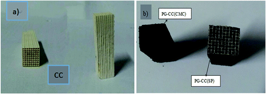
Commercial monoliths of cordierite were cut into portions of 1 × 1 cm2 with a length of 4.2 cm (Fig. 1). The cordierite pieces were subsequently coated without any other treatment.2.2. PG coating preparation
The slurry was prepared by mixing 10% PG and a small amount of binder (sesbania powder (SP) or sodium carboxymethyl cellulose (CMC) binder) with deionized water. The slurry was stirred into homogeneous slurry at room temperature for 10 min. A piece of cordierite was then immersed into the slurry and subjected to ultrasonic vibration for 1 h for facilitates the coating process. The monoliths were coated in a single step. After immersion, air was softly blown to eliminate the excess slurry to achieve a homogeneously thick film on the ceramic surface, and the PG-coated monoliths were dried in stove at 60 °C and 110 °C for 3 h and overnight, respectively, and finally calcined at 500 °C under N2 atmosphere for 3 h, these samples were labeled as PG–CC.2.3. Catalyst preparation
The PG–CC carriers (prepared as described in Section 2.2.) and CC were selected to load MnOx as the active phase for the SCR of NOx with NH3. The impregnation was carried out with a solution of manganese nitrate solution (50%) for approximately 24 h. After immersion, air was blown to eliminate the excess liquid, it was dried in a stove at 60 °C and 110 °C for 3 h and overnight, respectively, and afterwards calcined in oxygen flow at 300 °C for 3 h. The catalysts were labeled as Mnx/PG–CC and Mny/CC, where x and y represent the mass ratios of Mn/PG–CC and Mn/CC.These catalysts were evaluated in a continuous flow system with a total flow rate of 350 ml min−1, the typical composition of the reacting stream was 600 ppm NO, 600 ppm NH3, 3.0% O2 with balance N2, corresponding to a GHSV of 26![[thin space (1/6-em)]](https://www.rsc.org/images/entities/char_2009.gif) 000 h−1. The catalytic activities in the selective catalytic reduction were determined at temperature between 100 °C and 300 °C, while the reactor was heated from room temperature to 100 °C in a rate of 5 °C min−1, and then isothermally at 100 °C for 60 min. After this treatment, the temperature adjusted to the desired valued and each temperature segment insulation 1 hour, the products were analyzed by Germany TESTO Testo 340 type flue gas analyzer.
000 h−1. The catalytic activities in the selective catalytic reduction were determined at temperature between 100 °C and 300 °C, while the reactor was heated from room temperature to 100 °C in a rate of 5 °C min−1, and then isothermally at 100 °C for 60 min. After this treatment, the temperature adjusted to the desired valued and each temperature segment insulation 1 hour, the products were analyzed by Germany TESTO Testo 340 type flue gas analyzer.
2.4. Coating stability tests
The adhesion of the washcoat was evaluated by measuring the weight losses of samples subjected to ultrasonic (US) technique. This method was recently applied by Juan M. Zamaro19 for checking adherence of zeolite coating on monoliths and by Beers et al.20 for checking adherence of in situ zeolite growth on monoliths. The washcoated monoliths were put in a beaker containing water and submitted to ultrasonic treatment for 10 min. After the US treatment the monoliths were dried and calcined. The weight of the sample both before (m1) and after (m2) the ultrasonic treatment were measured. Moreover, the coating rate was quantified by calculation of the weight increase of the CC. The adhesion calculation formula is given by:| Loss rate = (m1 − m2)/m1 × 100% |
2.5. Characterization techniques
A Quantachrome NOVA (2200e) adsorption analyzer was used to measure the N2 adsorption isotherms of the samples at liquid-N2 temperature (−196 °C). The carriers were preheated at 200 °C for 3 h. The surface area was determined from the linear portion of the Brunauer–Emmett–Teller (BET) plot. The pore size distribution was calculated from the desorption branch of the N2 adsorption isotherms using Barrett–Joyner–Halenda (BJH) method.The Scanning Electron Microscope (SEM) images were taken on a scanning electron microscope (JEOL JSM-6490 LV, operated at 20 kV) with the objective of studying their morphology. The carriers were covered with a thin gold layer to prevent surface charging and improve the quality of the images.
3. Results and discussion
3.1. Coating stability
Thermal treatment is a critical issue for the mechanical stability of a layer in practical applications,21 an inappropriate calcination temperature could lead to loss or cracking of the coating.4 The effect of calcination temperature on the adhesion of the PG layers to the CC substrates was investigated, as shown in Table 1. It can be observed that the PG layers are more firmly attach to the CC substrates with increasing calcination temperature, achieving the best adherence at 600 °C. In this temperature, few loss of PG coating were found on the samples when subjected to severe US treatment, which suggests that the PG coating is well sintered with CC. Consequently, the PG–CC shows strong vibration-shock resistance, and the appropriate calcination binds the washcoat to the monolith walls.22 It is obviously that the PG layer cohesion is mostly due to the high calcination temperature. However, cracking and depression between the coating and substrate were observed and were attributed to the higher temperature. Even the coating carriers exhibited no weight loss during ultrasonic vibration, bump and depression reduced the long cycling of the catalyst. Comprehensive analysis indicated that the calcination temperature of 500 °C works well. In other case, these data demonstrate that CMC is a better binder than SP with respect to adherence of the coating, the binder here has two important effects (i) the small size particles fill out the space between aggregates thus increasing the contact between particles and improving the binding strength and (ii) CMC and SP have a high concentration of hydroxyl groups on its surface, allowing the formation of bonding with PG crystal after calcination, and the formation of bonding, CMC could do better than SP.| Temperature/°C | Binder | Coating rate/% | Loss rate/% |
|---|---|---|---|
| 200 | SP | 10.3 | 9.0 |
| CMC | 9.5 | 10.5 | |
| 300 | SP | 9.9 | 8.7 |
| CMC | 9.2 | 6.6 | |
| 400 | SP | 8.3 | 3.9 |
| CMC | 7.6 | 3.4 | |
| 500 | SP | 12.2 | 0.5 |
| CMC | 8.3 | 0 | |
| 600 | SP | 15.5 | 0 |
| CMC | 8.8 | 4.2 |
Viscosity as a fundamental property of slurries strongly influences the characteristics of the coating.23,24 Numerous researchers have demonstrated that the solid content and the particle sizes of coatings and binders influence the adhesion properties.25 In this work, the effect of the solid–liquid ratio and primary particle size of PG was investigated and the result is shown in Fig. 2 and 3. As can be seen in Fig. 2, without the binder, the coating rate increased along with the increasing in solid-to-liquid ratio, while the loss of coating is distinctly opposing to the coating rate. This phenomenon occurs because the solid–liquid ratio has a great effect on the property of the slurry. Obviously, the slurry with lower solid–liquid ratio can not cover the CC completely. Otherwise, a higher solid–liquid ratio may lead to the increasing in plastic viscosity and colloidal viscosity, so that the suspension slurry shows non-Newtonian system properties with poor flow properties. As a result, in case of higher solid–liquid slurry, nonuniform distribution on the CC and blocking of the pores and channels of CC are easier to happen, and the residue in the channels is not easy to blow down. Thus, the solid–liquid ratio of slurry was optimized at 2/17 for the flowing study.
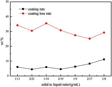 | ||
| Fig. 2 Influence of the solid-to-liquid ratio on the coating rate and on the coating loss rate during ultrasonic treatment. | ||
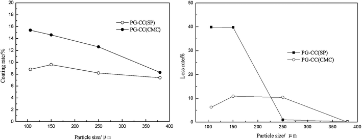 | ||
| Fig. 3 Influence of the particle sizes of coatings on the coating rate and on the coating loss rate during ultrasonic treatment. | ||
Fig. 3 shows the effect of particle size on the coating rate and loss rate during ultrasonic treatment. It can be seen that a smaller particle size of PG led to a higher PG loading, which was likely because of the combination effect of viscosity. The PG layer was removed easily when the particle size was less than 250 μm, which was agreed with the polarity consistency principle.
This result can be explained by that the slurry prepared with small PG particles showed stable performance and could form a uniform layer during the coating process. The coating load varied with the slurry viscosity, which affects the interface between the PG and CC.26 The spreading and penetration of the slurry in the channel wall were diminished when the coating weight was increased,27 and the loss rate increased rapidly. These results demonstrated the advantages of CMC in improving the adhesion of coatings with various PG particle size. The appropriate size of PG particles was less than 380 μm.
3.2. Characterization of carriers
The BET surface area, pore volume, and pore size of different carriers calcined at 500 °C (9% coating rate) are summarized in Table 2. It is obvious that the BET surface area and pore volume significantly increased after the PG coating onto the cordierite, which can be attributed to the high surface area and pore structure of PG. Compared to PG–CC(SP), PG–CC(SP)UT (subjected to ultrasonic treatment) had the similar pore volume and pore diameter, but the specific surface area was reduced by 8 m2 g−1. These may be attributed to the change of PG microstructure and the flaking off of some PG coating from the CC substrate. After the ultrasound treatment, the surface area and pore diameter of PG–CC(CMC)UT were similar to PG–CC(CMC) while the pore volume was changed. Furthermore, the PG–CC(CMC) carrier exhibited better mechanical stability than the PG–CC(SP) carrier (Table 2).| Samples | BET surface area (m2 g−1) | Pore volume (cm3 g−1) | Pore diameter (nm) |
|---|---|---|---|
| CC | 1.7 | 0.0016 | 3.7 |
| PG–CC(SP) | 15.9 | 0.056 | 4.069 |
| PG–CC(CMC) | 15.1 | 0.064 | 3.217 |
| PG–CC(SP)UT | 8.3 | 0.053 | 4.071 |
| PG–CC(CMC)UT | 11.8 | 0.039 | 4.069 |
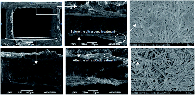
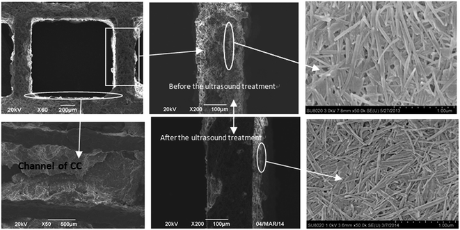
The cross-section of PG–CC(SP) and PG–CC(CMC) before and after ultrasonic vibration are shown in Fig. 4 and 5. The micrograph of the channel walls (Fig. 4a, b and d and 5a, b and d) showed that PG layer with no crake was produced. This may be attributed to the chemical bonding strength between the cordierite substrate and PG layer.28 Additionally, the layer thickness was not homogeneous and it was thick at the corners of the square cells (Fig. 4a, b and d and 5a, b and d). The difference in thickness was caused by the fluid dynamic phenomena during the blowing step of the PG deposition procedure.29 As shown in Fig. 4e and f and 5e and f, the PG layer with CMC binder (PG(CMC)) exhibited almost no damage regions after the ultrasonic vibration, but the PG layer with SP binder (PG(SP)) appeared to bound loosely to the substrate. PG–CC(CMC) showed no loss rate, while PG–CC(SP) had a 5% loss rate after the same US treatment time (Table 1). These revealed a strong interaction of the coating layer and the CC substrate.
3.3. Catalyst activity
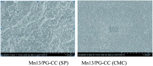
In our previous work, it was found that the catalytic activity of PG catalyst for the SCR of NO with NH3 was significantly promoted by loading of MnOx.30 The preliminary activity test was performed by the manganese-based catalysts as shown in Fig. 6. It can be seen that the PG–CC was almost inactive in 100–300 °C, whereas Mn13/PG–CC showed high activity especially in the temperature range of 150 to 300 °C (above 90%). The catalytic activity of Mn13/CC was clearly lower than that of Mn13/PG–CC. The PG layer had two main effects except for the large surface area: a synergistic catalytic effect with Mn for the low-temperature SCR reaction and the adsorption for NOx/NH3. It should be pointed out that the NOx conversion of Mn13/PG–CC(SP) was higher than that of Mn13/PG–CC(CMC) at 100 °C, which may be attributed to the differences of their BET surface areas (Table 2). The large surface areas led to better Mn dispersion and more Mn exposed on the surface, which improved the NOx conversion activity.31 These were confirmed by the SEM images in Fig. 7. Compared Fig. 7a and b, the knitting structure of PG was disappeared and the CC was filled with granule. The granules of Mn13/PG–CC(CMC) (Fig. 7b) were more uniform and denser than that of Mn13/PG–CC(SP) (Fig. 7a), this structure was consistent with the result of loss rate in Table 1. So the binder had an important effect on the distribution of active substances, and the NO removal activity of Mnx/PG–CC catalyst.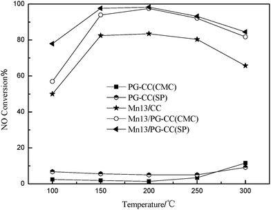 | ||
Fig. 6 Activities of catalysts and carriers toward the SCR of NOx by NH3. Reaction conditions: [NO] = [NH3] = 600 ppm, 3% O2, Ar as balance gas, gas hourly space velocity = 26![[thin space (1/6-em)]](https://www.rsc.org/images/entities/char_2009.gif) 000 h−1. 000 h−1. | ||
4. Conclusions
The PG coating improved the texture of the CC substrates, resulting in an increase in the amount of loaded active component and an enhancement of catalyst activity. The catalytic activity performance of Mn13/PG–CC demonstrated that the properties of the carriers were maintained after the coating process. The optimal calcinations temperature was 500 °C and the appropriate PG particle size was less than 380 μm. Mn13/PG–CC catalyst showed a catalytic activity of 98% in the temperature range of 150–250 °C. In view of application, Mnx/PG–CC catalyst with high catalytic activity at 100–150 °C had potential application for NOx purification of diesel exhaust.Acknowledgements
The study is financially supported by the National Natural Science Foundation of China (No. 40902020, 51002042, and 21203003), the Special Research Foundation of Doctor Program (No. 20090111120019), the Fundamental Research Funds for the Central Universities (No. 2011HGQL103), and the Anhui Provincial Natural Science Foundation (No. 1308085QB44).References
- Y. Wan, X. T. Cui and Z. T. Wen, J. Hazard. Mater., 2011, 198, 216 CrossRef CAS PubMed.
- A. F. Pere-Cadenas, F. Kapteijn, J. A. Moulijin, F. J. Maldonado-Hódar, F. Carrasco-Marín and C. Moreno-Castilla, Carbon, 2006, 44, 2463–2468 CrossRef.
- T. Q. Zhou, L. D. Li, C. Jie, Q. Shen, Q. Xie and Z. P. Hao, Ceram. Int., 2009, 35, 3097–3101 CrossRef CAS.
- D. M. Gómez, J. M. Gatica, J. C. Hernández-Garrido, G. A. Cifredo, M. Montes, O. Sanz, J. M. Rebled and H. Vidal, Appl. Catal., B, 2014, 144, 425–434 CrossRef.
- C. B. Chen, P. Li, Z. J. Sui and Y. Wang, Ind. Catal., 2010, 18, 40 CAS.
- E. Soghrati, M. Kazemeini, A. M. Rashidi and K. J. Jozani, J. Taiwan Inst. Chem. Eng., 2014, 45, 887–895 CrossRef CAS.
- A. F. Pérez-Cadenas, F. Kapteijn, M. M. Zieverink and J. A. Moulijn, Catal. Today, 2007, 218, 13–17 CrossRef.
- J. C. Wang, Z. L. Peng, Y. Chen, W. R. Bao, L. P. Chang and G. Feng, Chem. Eng. J., 2015, 263, 9–19 CrossRef CAS.
- H. Zhou, Y. X. Sua, W. Y. Liao, W. Y. Deng and F. C. Zhong, Appl. Catal., A, 2015, 505, 402–409 CrossRef CAS.
- S. D. Zhang, P. C. Wu, L. Q. Yang, Y. H. Zhou and H. Zhong, Catal. Commun., 2015, 71, 61–64 CrossRef CAS.
- S. M. Shamshuddin, M. S. Sundar, N. Thimmaraju, Venkatesh, G. Vatsalya and M. Senthilkumar, C. R. Chim., 2012, 15, 799–807 CrossRef.
- D. F. Wu, J. C. Zhou and Y. D. Li, Am. Inst. Chem. Eng. J., 2007, 53, 2618–2629 CrossRef CAS.
- J. G. Zou and Q. Zhong, Environ. Eng., 2005, 33, 1028–1031 CAS.
- J. G. Zou and Q. Zhong, China Environ. Sci., 2005, 25, 531–534 CAS.
- J. G. Zou, Q. Zhong and B. C. Wun, Non-Met. mines, 2005, 28, 44–46 CAS.
- J. G. Zou and Q. Zhong, J. Chin. Ceram. Soc., 2005, 23, 35–37 CAS.
- R. B. Jin, Y. Liu, Y. Wang, W. L. Cena, Z. B. Wu, H. Q. Wang and X. L. Weng, Appl. Catal., B, 2014, 148–149, 582 CrossRef CAS.
- M. A. Kord, I. D. Savaris, E. E. Feistauer, L. S. Barreto, N. C. Heck, I. L. Müller and C. F. Malfatti, Int. J. Hydrogen Energy, 2013, 38, 4760–4766 CrossRef.
- J. M. Zamaro, M. A. Ulla and E. E. Miro, Catal. Today, 2005, 107–108, 86–93 CrossRef CAS.
- A. E. W. Beers, T. A. Nijhuis, F. Kapteijn and J. A. Moulijn, Microporous Mesoporous Mater., 2001, 48, 279–284 CrossRef CAS.
- S. Azalim, R. Brahmo, M. Agunaou, A. Beaurain, J. Giraudon and J. Lamonier, Chem. Eng. J., 2013, 223, 536–546 CrossRef CAS.
- J. M. Zamaro, M. A. Ulla and E. E. Mirò, Chem. Eng. J., 2005, 106, 25–33 CrossRef CAS.
- Z. Q. You, G. Z. Liu, L. Wang and X. W. Zhang, Microporous Mesoporous Mater., 2013, 170, 235–242 CrossRef CAS.
- T. A. Nijhuis, A. E. W. Beers, T. Vergunst, I. Hoek, F. Kapteijn and J. A. Moulijn, Catal. Rev., 2001, 43, 345 CAS.
- J. R. Gonzalez-Velasco, M. A. Gutierrez-Ortiz, J. L. Marc, J. A. Botas, M. P. Gonzalez-Marcos and G. Blanchard, Ind. Eng. Chem. Res., 2003, 42, 311–317 CrossRef CAS.
- H. F. Huang, L. L. Jin, H. F. Lu, H. Yu and Y. J. Chen, Catal. Commun., 2013, 34, 1–4 CrossRef.
- V. Meille, S. Pallier, G. V. S. C. Bustamante, M. Roumanie and J. P. Reymond, Appl. Catal., A, 2005, 286, 232–238 CrossRef CAS.
- Z. T. Huang and J. M. Geng, Industrial Catalysis, Chemical Industry Press, China, 2006, p. 139 Search PubMed.
- E. D. Banús, V. G. Milt, E. E. Miró and M. A. Ulla, Appl. Catal., B, 2013, 132–133, 479–486 CrossRef.
- X. L. Zhang, S. S. lv, C. P. Zhang, X. P. Wu, L. F. Zhang, J. W. Wang, X. B. Jia and H. J. Zhang, Chem. Pap., 2015, 69, 1548–1555 CAS.
- J. M. Zamaro, M. A. Ulla and E. E. Miró, Chem. Eng. J., 2005, 106, 25–33 CrossRef CAS.
| This journal is © The Royal Society of Chemistry 2016 |

