Full alignment of dispersed colloidal nanorods by alternating electric fields†
M. Mohammadimasoudi*ac,
Z. Hensbc and
K. Neyts*ac
aElectronics and Information Systems Department, Ghent University, Zwijnaarde 15, B-9052 Gent, Belgium. E-mail: mohammad.mohammadimasoudi@elis.ugent.be; kneyts@elis.ugent.be
bPhysics and Chemistry of Nanostructures, Ghent University, Krijgslaan 281-S3, 9000 Gent, Belgium
cCenter for Nano- and Biophotonics, Ghent University, Belgium
First published on 6th June 2016
Abstract
The parallel alignment of an ensemble of colloidal nanorods may unleash their application as the optically anisotropic constituent in polarized fluorescent sheets or polarization-selective detectors. Here, we demonstrate that full alignment of colloidal CdSe/CdS nanorods in suspension can be achieved by applying AC electric fields. Alignment is monitored by the concurrent change of the optical transmission of the dispersion. By comparing the transmission measurements to a theoretical model encompassing both the permanent and induced dipole moments of the nanorods, we can attribute the alignment to the interaction between the electric field and the nanorod's permanent dipole moment. The permanent dipole moment, relaxation time, absorption anisotropy and critical frequency of the CdSe/CdS nanorods are determined. In addition, we show that the regime of full alignment enables the direct determination of the anisotropic absorption of CdSe/CdS nanorods. We find that the anisotropy in absorption for the CdSe dot is similar to that of the CdS rod, which we attribute to the similarity in dielectric constant and electric field in both materials.
Introduction
Over the last 30 years, colloidal nanocrystals have attracted wide scientific and technological interest since their opto-electronic properties can be tuned by means of their size and shape. Whereas size is the key parameter underlying quantization in semiconductor nanocrystals1 and the occurrence of localized surface plasmon resonances in metal nanocrystals,2 shape often adds unique possibilities to further adjust the nanocrystal properties.3 In this respect, rods and platelets stand out since their shape anisotropy results in an anisotropic interaction – absorption, emission or scattering – with light.4 Metallic nanorods, for example, exhibit a splitting of the localized surface plasmon resonance into a longitudinal and transversal mode that most strongly interacts with light polarized perpendicular or parallel to the long axis of the rod, respectively.2 Rod-like colloidal semiconductor nanocrystals such as CdSe quantum rods or CdSe/CdS dot-in-rods on the other hand more strongly absorb and emit light polarized parallel to their long axis.5,6Although use can be made of the anisotropic properties of single nanorods,2,7,8 applications such as polarized light emitting diodes,9 photovoltaic energy conversion, optical sensors or switches10–13 require layers or volumes with large ensembles of aligned nanorods. In this context, various methods for the collective alignment of colloidal nanorods have been explored. Focusing on colloidal quantum rods, these either exploit the tendency of nanorods to self-assemble by aligning their long axes upon drying or dispersion destabilization or involve the use of external forces to impose rod alignment. Depending on the actual conditions, slow solvent evaporation on a solid substrate or a liquid subphase results in nanorod films aligned with their long axis parallel or perpendicular to the substrates.14–19 Alternatively, alignment by external forces has been demonstrated using mechanical rubbing of a pre-deposited film of randomly oriented quantum rods20 or by means of electric fields applied either during solvent drying21–23 or to achieve electrophoretic deposition.24
Besides the alignment of nanorods during deposition, a number of studies have addressed the alignment of quantum rods in solution. Various reports describe the organization of nanorods in two-dimensional sheets of a single layer of parallel quantum rods by depletion attraction,25 specific surface functionalization schemes26 or a reduction of the dispersion stability.27,28 Although it proved possible to orient such 2D sheets in solution by magnetic fields,29 the size of the sheets leads to considerable scattering of light and results in patchy deposits upon solvent drying. Opposite from this alignment-by-aggregation, the collective orientation or alignment of non-aggregated nanorods is possible by means of an electric field. Although electrical alignment has mainly been used to characterize nanorod properties such as the dipole moment30 or the absorption anisotropy,31 it can be regarded as a technical solution to produce functional solid films with strong anisotropy in optical absorption, emission or scattering. For example, alignment-in-solution can be achieved in a polymerizable medium, where a triggered polymerization can lock the rod orientation to produce self-supporting films or sheets of aligned nanorods. Such an approach can have several advantages. Depending on the electrode configuration, the alignment can be homogenous or follow a pattern. Moreover, in-solution alignment by an electric field is also possible at low nanorod concentrations, thus leading to films with a desired absorption coefficient for, e.g., optical down-conversion applications in lighting, displays or luminescent solar concentrators.
Despite the potential of in-solution alignment of nanorods by electric fields, both theoretical and experimental aspects have only been partially studied in the literature. Ruda et al. gave a theoretical description of the alignment of gold nanorods based on the anisotropy of the induced dipole moment.32 In the case of semiconductor nanorods on the other hand, the alignment by alternating electric fields is typically attributed to a permanent dipole along their long axis,21,30,31 although the presence of a permanent dipole could not be confirmed by electrostatic force microscopy.33 In addition, there are no reports about reaching the regime of full nanorod alignment in the literature. Using the available combination of applied fields and quantum rod dipoles, Kamal et al. only obtained partial orientation, as the electrostatic energy gained by orienting the rods was at best about equal to the thermal energy,31 while an even weaker orientation can be deduced from the figures provided by Li et al.30
In this paper, we demonstrate that colloidal CdSe/CdS nanorods that are dispersed in a non-polar solvent can be quasi fully aligned by applying sufficiently strong alternating electric fields. The degree of alignment is monitored by measuring the transmission31 as a function of time during the application of a time-dependent voltage. The measurement results are interpreted by using a dynamic model that encompasses the viscous drag of the solvent, the rotational diffusion of the nanorods, the torque due to the permanent dipole moment and the (induced) dielectric torque. The transition from random to full alignment as a function of the electric field enables us to attribute the alignment to the nanorods' permanent dipole and determine the dipole's magnitude. In addition, we show that full alignment and relaxation are established with characteristic time constants of 50 μs or less. Finally, we demonstrate that the regime of full alignment is ideal to quantify the absorption anisotropy of colloidal NRs, where we find that the small dielectric mismatch between the CdS rod and the CdSe dot makes that CdSe-dot and CdS-rod related optical transitions feature a similar absorption anisotropy.
Experimental
CdSe/CdS nanorod synthesis
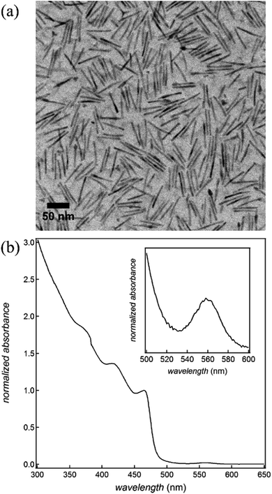
CdSe/CdS dot-in-rods are synthesized according to a procedure described in the literature (see ESI S1† for synthesis details).23 In brief, CdSe quantum dots (QDs) with a wurtzite structure and an average diameter of 2.3 nm are synthesized first. On these core QDs, an anisotropic CdS shell is grown using phosphonic acids as the ligands to obtain CdSe/CdS dot-in-rods, which we will denote as CdSe/CdS nanorods (NRs). Fig. 1 provides an overview of the most important characteristics of the NRs used in this study. Based on the transmission electron micrograph (Fig. 1a), their average diameter and length are estimated at 4.8 and 51.5 nm, respectively. Moreover, their absorbance spectrum (Fig. 1b) indicates that they have a first exciton or band-gap transition at 560 nm, whereas the absorbance by the CdS rod starts dominating at wavelengths below 500 nm.Quantum rod alignment by electric fields
As shown in Fig. 2a, a cell is made by joining two glass substrates with 1 cm2 ITO electrodes with glue containing 20 or 50 μm spacer beads (Sekisui Chemicals) to ensure a uniform cell gap d between the electrodes.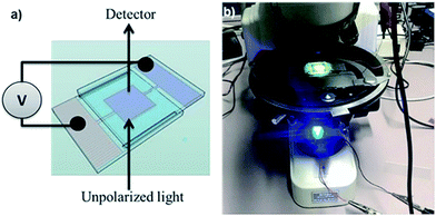 | ||
| Fig. 2 (a) Schematic view of the cell used to align dispersed nanorods by means of electric fields and (b) image of the microscope transmission setup. | ||
The cell is filled with the CdSe/CdS NR suspension by capillary force (see ESI S2†). A function generator (TTi-TG315) and a voltage amplifier are used to apply a high AC voltage V with a frequency between 50 Hz and 40 kHz over the cell. This results in electric fields – estimated as E = V/d – of up to 40 V μm−1 in the dispersion. The transmission of blue (470 nm) and green (560 nm) LED light is measured using a photodetector (FLC electronics-PIN20) mounted on a microscope (Nikon-eclipse E400). Fig. 2b shows part of the setup including the cell and the blue LED.
Theoretical background
Orientation of spheroids in an electric field
As sketched in Fig. 3a, the application of a voltage difference across the cell, and thus an electric field inside the dispersion, will change the random orientation of the long axis of the NRs into a preferential alignment along the electric field. To describe this electric-field driven alignment of NRs dispersed in an apolar liquid, we consider both their permanent and induced (dielectric) dipole moments. Whereas CdSe/CdS NRs have a permanent dipole moment that is related to their non-centro-symmetric wurtzite crystal structure, the induced dipole moment cannot be neglected a priori since semiconductor NRs typically have a considerably higher dielectric constant than the surrounding apolar liquid.To assess the characteristic times determining the motion of NRs under the action of an alternating field, we use a dynamic equation that takes into account both the dielectric and dipolar torques, thermal fluctuations and rotational viscosity of the NRs. When a NR – approximated as a prolate ellipsoid of revolution – is placed in a host medium with dielectric constant εh in which a homogeneous external field E is present, the induced dipole moment pind with respect to the host medium amounts to:
| pind = α∥ε0E∥1∥ + α⊥ε0E⊥1⊥ | (1) |
 | (2) |
In the above expression, V represents the volume of a NR and L∥ and L⊥ are the depolarization factors for fields parallel and perpendicular to the NR long axis, respectively. With a and b the length of the corresponding semi-axes of the ellipsoid (see Fig. 3c), these read:35
 | (3) |
The induced dipole moment leads to a dielectric or induced torque on the NR given by:
 | (4) |
If the NR has a permanent dipole moment p along the long axis of the NR, then the external electric field leads to an additional dipolar torque Tdip:
Tdip = p × E = pE![[thin space (1/6-em)]](https://www.rsc.org/images/entities/char_2009.gif) cos cos![[thin space (1/6-em)]](https://www.rsc.org/images/entities/char_2009.gif) θ1′⊥ θ1′⊥
| (5) |
Including the two torques into the dynamic equation of reorientation yields the following differential equation for the orientation angle θ:
 | (6) |
The first term of eqn (6) contains the moment of inertia I and is usually negligible for small ellipsoids, except at very high frequencies (i.e., MHz range). The second term represents the viscous torque, whereas the first term on the right is the torque due to Brownian motion,36 with kB the Boltzmann constant and T the absolute temperature. In both expressions, γr is the rotational viscosity:32
 | (7) |
Using eqn (6), we can estimate the typical time τon it takes to align an ellipsoid when switching on a sufficiently strong electric field by neglecting the Brownian term, replacing the derivative by the ratio Δθ/τon, and setting Δθ = π/4:
 | (8) |
The typical time for reorientation when switching off the voltage is called the relaxation time τrel, which is usually longer than τon. This time and the relaxation frequency can be estimated using the Debye–Perrin model and eqn (6):
 | (9) |
The excess electrostatic energy Uel of a stationary ellipsoid in an electric field is given by:
 | (10) |
In the quasi-static case, when the frequency of the field is well below frel and fon, the probability P(θ) to find an ellipsoid within a given solid angle making an angle θ with the long axis of the rod is proportional to the Boltzmann distribution:
 | (11) |
Light absorbance by dispersed ellipsoidal particles
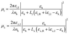
When a light absorbing ellipsoidal nano-object is dispersed in a non-absorbing solvent, the effective absorption coefficient for light depends on the orientation of the particle relative to the incident electric field. Based on the depolarization factors parallel and perpendicular to the long axis of the ellipsoid, we can write down the intrinsic absorption coefficients based on the Maxwell Garnett model37
 | (12) |
In this expression, nh is the refractive index of the host solvent and ε∥,R + iε∥,I and ε⊥,R + iε⊥,I are the complex dielectric constant of the nanorod for the considered wavelength in the directions parallel and perpendicular to the NR long axis, respectively. In the typical situation for semiconductor NRs in an apolar solvent, their magnitude exceeds εh, resulting in a screening of the electric field by the NRs. For a prolate ellipsoid, L∥ is smaller than L⊥ such that the absorption coefficient for parallel orientation is the larger of the two. For an ellipsoid with inclination θ and azimuth φ as shown in Fig. 3c, the absorption coefficient will be an average of μ∥ and μ⊥, weighted by the square of the projection of the electric field:
μ(θ, φ) = μ∥cos2![[thin space (1/6-em)]](https://www.rsc.org/images/entities/char_2009.gif) φ φ![[thin space (1/6-em)]](https://www.rsc.org/images/entities/char_2009.gif) sin2 sin2![[thin space (1/6-em)]](https://www.rsc.org/images/entities/char_2009.gif) θ + μ⊥(1 − cos2 θ + μ⊥(1 − cos2![[thin space (1/6-em)]](https://www.rsc.org/images/entities/char_2009.gif) φ φ![[thin space (1/6-em)]](https://www.rsc.org/images/entities/char_2009.gif) sin2 sin2![[thin space (1/6-em)]](https://www.rsc.org/images/entities/char_2009.gif) θ) θ)
| (13) |
For an ensemble of ellipsoids, the absorption coefficient μ in eqn (13) is obtained by averaging over all orientations of the NR long axis, weighted with the corresponding Boltzmann factor (eqn (11)):
 | (14) |
Finally, the absorbance A of a dispersion of ellipsoidal nano-objects is given by the products of the intrinsic absorption coefficient μ and the volume fraction f of the ellipsoids and the path length d of light through the dispersion, divided by the natural logarithm of 10:
 | (15) |
Results and discussion
Full alignment of colloidal NRs by electric fields
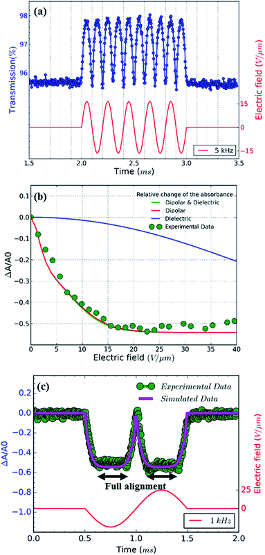
To explore the alignment of dispersed colloidal NRs by electric fields, a dodecane-based dispersion of CdSe/CdS NRs is loaded in a cell as described in the Experimental section. As a fraction of the NRs will carry an electric charge,38 application of a DC field will make the NRs drift to the electrodes. To avoid artefacts due to NR accumulation at the electrodes, we use AC fields with a period shorter than the cell transit time τcell = d/uE where u is the mobility of the NRs. As shown in the ESI,† NRs in a 50 μm cell have a cell transit time of ≈5 ms for fields of 17 V μm−1. Therefore, we use frequencies higher than 200 Hz to study NR alignment.A first measurement involves the optical transmission of a 50 μm cell filled with a 1 μM dispersion of NRs in dodecane at 470 nm in the presence of a sinusoidal AC electric field. An example is given in Fig. 4a, where it can be seen that the two extreme values of the electric field during a single period both correspond to a maximum increase of the transmission (see also the transmission of the cell in presence of a block wave electric field in ESI, Fig. S3†). From these transmission measurements, the absorbance A by the NR dispersion is calculated as:
 | (16) |
In order to eliminate the trivial influence of cell thickness and NR concentration from the measurements, we introduce the relative change of the absorbance ΔA/A0 (usually <0):
 | (17) |
Dynamical properties of colloidal NR alignment
Next to the levelling off of the absorbance change, Fig. 4c also makes clear that the change in absorbance is established without noticeable delay. This indicates that at the fields and frequencies used, the NRs readily flip from a θ = 0° to a θ = 180° orientation when the field changes direction (see Fig. 3c for a definition of the angle θ).Hence, the NR reorientation occurs on a time scale much shorter than the 1 ms period of the AC field, an outcome in line with the dynamical properties of NR (re)orientation. Indeed, using eqn (7) and (9), the rotational relaxation frequency frel in dodecane of the CdSe/CdS NRs used here can be estimated at 13 kHz (see ESI S4, Table S1†).
Hence, fields with a frequency well below 13 kHz, should give the NRs enough time to establish a quasi-equilibrium Boltzmann distribution that follows the variation of the electric field, thus bringing them from random orientation to full alignment. In line with this, increasing the AC frequency from 1 to 10 kHz only changes the frequency at which the transmission changes, without affecting the limiting value corresponding to full alignment (see ESI S5†). Hence, the only difference between a 1 and a 10 kHz field is that the latter makes the NRs flip faster between the θ = 0° to a θ = 180° orientation.
At frequencies above frel, we expect that the distribution will not return to random alignment and the minimum in the transmission will not be as low as the zero-field transmission. Moreover, the NRs will stop reacting to the AC field once the frequency exceeds the turn on frequency fon, which is estimated at ≈100 kHz in this case (see ESI S4, Table S1†). This description of the NR orientation dynamics is further confirmed by the response of the transmission to a single block pulse with an amplitude of 17 V μm−1. As shown in Fig. 5, the regimes of full alignment and de-alignment are reached within less than 50 μs.
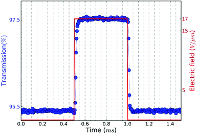 | ||
| Fig. 5 Transmission versus time of a CdSe/CdS NR suspension in dodecane when a pulse with amplitude of 17 V μm−1 is applied. | ||
Permanent versus induced dipole moments
As the absorbance of the CdSe/CdS NRs at 470 nm will be dominated by the CdS rod (Fig. 1b), the bulk optical constants of CdS can be used to estimate the dielectric function of the nanorod in the expressions for the polarizability and the absorption coefficient of dielectric ellipsoids, i.e., eqn (2) and (14), respectively. The thus calculated polarizability and absorption coefficients at 470 nm have been summarized in ESI S4, Table S1.† Using these figures, the degree of orientation and the concomitant relative absorbance change can be calculated if only the dielectric torque were present. The thus predicted dependence of ΔA/A0 on the electric field strength has been added to Fig. 4b, where it follows that fields of more than 40 V μm−1 would be needed to obtain an appreciable alignment of the NRs. We therefore conclude that the (full) alignment of the NRs is indeed due to the permanent dipole moment of the NRs. Considering the NR dipole moment p as an adjustable parameter, the field dependence of ΔA/A0 can again be predicted. Fig. 4b shows that taking p = 1500 D, a typical value for the CdSe/CdS NRs used here, makes the simulated field dependency of ΔA/A0 closely match the experimental data. We stress that this predicted trend depends on a single adjustable parameter, i.e., the dipole moment p, which mainly determines the region of electric fields where the NRs change from random to full alignment. The high-field limit of ΔA/A0 on the other hand only depends on the difference in absorption coefficient of fully aligned (μ⊥) and randomly aligned (μ0) quantum rods:
 | (18) |
Inserting the estimated absorption coefficients (see ESI, Table 1†), a limit of −0.54 is obtained, in line with the experimental findings.
Absorption anisotropy at the band–edge transition
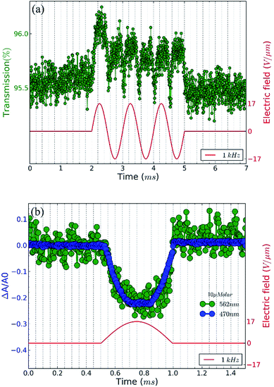
As indicated by eqn (18), the regime of full alignment provides a way to directly determine the absorption anisotropy of colloidal NRs at any given wavelength. We therefore extended the analysis to the NR absorbance at the CdSe/CdS first exciton transition at around 560 nm (see Fig. 1b), which is due to electronic transitions between quantized states in the CdSe core. To adjust for the absorbance difference at 470 and 560 nm of the CdSe/CdS NRs, we had to analyze NR dispersions with a concentration 10 times higher than used for the previous measurements. Hence, we now measure the transmission of green light (≈560 nm) through a 50 μm thick cell filled with a 10 μM NR dispersions in the presence of an AC electric field (17 V μm−1, 1 kHz). Fig. 6a shows that the AC field leads to a similarly oscillating increased transmission – meaning a decrease in absorbance – as observed before at 470 nm. Hence, also the CdSe core transitions exhibit a marked absorption anisotropy. An issue with the more concentrated dispersions used here is that a considerable fraction of the NRs form aggregates that are not oriented by the applied electric field. Fig. 6b therefore compares the relative change of the absorbance determined at 560 nm with that determined at 470 nm for the same dispersion under the same conditions of the applied field. Since this transmission change would reach −0.54 if all rods aligned, the actual plateau value can be used to estimate the fraction of NRs that can be aligned and thus calibrate the transmission changes at 560 nm.Fig. 6b shows that this calibration is actually quite straightforward since the high-field limit of ΔA/A0 (eqn (17)) at 560 nm due to CdSe core absorption is very similar to the one measured at 470 nm, which is due to absorption in the CdS rod. Hence, a quite similar corrected limiting value of ΔA/A0 in the range −0.5 to −0.55 is obtained at the band-gap transition as well. This result may seem surprising since the core is a spherically symmetric object, yet it can be understood by realizing that the dielectric mismatch between the CdSe core and the CdS shell is small.
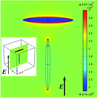
To clarify this point, Fig. 7 shows the electric field distribution within a CdS ellipsoid encompassing a CdSe sphere and surrounded by dodecane as a host. This field has been obtained from a 3D finite element field calculation modelling all materials by means of the real parts of the anisotropic bulk dielectric functions at 560 nm (see ESI S4, Table S2†). Regardless of the orientation of the NR relative to the external field, we find that the internal field in the CdSe core amounts to ≈95% of the field in the CdS host.
Moreover, the electric field in the rod (and thus the sphere) is almost identical to the external electric field when the applied field is parallel to the c-axis of the rod, while it is only about half the applied external field for the perpendicular orientation.
These internal fields closely agree with the internal fields in CdS-only ellipsoids with depolarization factors L∥ = 0.018 and L⊥ = 0.49 dispersed in dodecane. The CdSe core thus experiences the same enhanced or reduced screening of the internal field as the CdS rod for incident optical fields perpendicular to or parallel with the long axis of the NR. Hence the largely similar absorption anisotropy for the quantum-dot band gap transition.
Note that the experimentally determined high-field limit of ΔA/A0 corresponds to a polarization ratio of 64% for the emission (see ESI, S6†), which is similar to the experimentally determined values of up to 75% as determined on single CdSe/CdS NRs.5
Conditions to reach full alignment
According to formula (11), full alignment is obtained when the difference in electrostatic energy Uel between parallel and perpendicular alignment is considerably larger than kT. Because we found that the contribution from the induced dipole moment is relatively small, the difference in electrostatic energy is in good approximation given by −Ep according to eqn (10). Based on the experimental result that a dipole moment of 1500 D requires a threshold field Eth of 17 V μm−1, we can estimate the field necessary to align dipoles with a different dipole moment p by:
 | (19) |
Conclusions
We have shown that colloidal CdSe/CdS NRs can be fully aligned in a colloidal dispersion by the application of AC electric fields with an appropriate field strength. The alignment is monitored by measuring the variation of the transmission concurring with the oscillation of the electric field at wavelengths where the CdS rod absorption dominates. For the rods used, complete alignment parallel with the electric field is obtained for field strengths exceeding 15 V μm−1 and switching back and forth to random orientation occurs within 50 μs. We develop a theoretical description of the relation between the electric field and the alignment of dielectric ellipsoidal nano-objects, considering both a permanent and an induced dipole moment. Doing so, it follows that the experimentally determined alignment as a function of field strength can be attributed to the interaction between the NR permanent dipole and the applied AC field.Since the transmission change in the regime of full alignment only depends on the difference between the NR absorption coefficient for optical fields parallel and perpendicular to the NR long axis, transmission measurements during AC driven full alignment provide an excellent method to measure anisotropic absorption by NRs. Excellent agreement between experiment and theory is obtained for the absorption anisotropy at 470 nm, i.e., wavelengths where the rod absorption dominates. Moreover, we find that band–edge transition exhibits a quite similar absorption anisotropy, a result we attribute to the small dielectric mismatch between the CdSe core and the CdS rod.
Acknowledgements
This research was supported by the Interuniversity Attraction Poles program of the Belgian Science Policy Office, under grant IAP P7-35.References
- E. R. Smith, J. M. Luther and J. C. Johnson, Nano Lett., 2011, 11, 4923–4931 CrossRef CAS PubMed.
- J. Cao, T. Sun and K. T. V. Grattan, Sens. Actuators, B, 2014, 195, 332–351 CrossRef CAS.
- M. Shim and H. McDaniel, Curr. Opin. Solid State Mater. Sci., 2010, 14, 83–94 CrossRef CAS.
- Z. Hens and I. Moreels, J. Mater. Chem., 2012, 22, 10406–10415 RSC.
- F. Pisanello, L. Martiradonna, P. Spinicelli, A. Fiore, J. P. Hermier, L. Manna, R. Cingolani, E. Giacobino, A. Bramati, M. De Vittorio and Ieee, Polarized Single Photon Emission for Quantum Cryptography Based on Colloidal Nanocrystals, Ieee, New York, 2009 Search PubMed.
- R. Krahne, G. Morello, A. Figuerola, C. George, S. Deka and L. Manna, Phys. Rep., 2011, 501, 75–221 CrossRef CAS.
- K. Becker, J. M. Lupton, J. Muller, A. L. Rogach, D. V. Talapin, H. Weller and J. Feldmann, Nat. Mater., 2006, 5, 777–781 CrossRef CAS PubMed.
- W. S. Chang, J. W. Ha, L. S. Slaughter and S. Link, Proc. Natl. Acad. Sci. U. S. A., 2010, 107, 2781–2786 CrossRef CAS PubMed.
- A. Rizzo, C. Nobile, M. Mazzeo, M. De Giorgi, A. Fiore, L. Carbone, R. Cingolani, L. Manna and G. Gigli, ACS Nano, 2009, 3, 1506–1512 CrossRef CAS PubMed.
- M. Fisher, M. Zanella, D. J. Farrell, L. Manna, P. Stavrinou and A. J. Chatten, 2011 37th IEEE Photovoltaic Specialists Conference (PVSC 2011), 2011, pp. 000858–000863 Search PubMed.
- C. Nobile, V. A. Fonoberov, S. Kudera, A. Della Torre, A. Ruffino, G. Chilla, T. Kipp, D. Heitmann, L. Manna, R. Cingolani, A. A. Balandin and R. Krahne, Nano Lett., 2007, 7, 476–479 CrossRef CAS PubMed.
- F. Liu, J. Wang, Z. Ge, K. Li, H. Ding, B. Zhang, D. Wang and H. Yang, J. Mater. Chem. C, 2013, 1, 216–219 RSC.
- A. Persano, M. De Giorgi, A. Fiore, R. Cingolani, L. Manna, A. Cola and R. Krahne, ACS Nano, 2010, 4, 1646–1652 CrossRef CAS PubMed.
- A. Singh, R. D. Gunning, S. Ahmed, C. A. Barrett, N. J. English, J. A. Garate and K. M. Ryan, J. Mater. Chem., 2012, 22, 1562–1569 RSC.
- C. Querner, M. D. Fischbein, P. A. Heiney and M. Drndic, Adv. Mater., 2008, 20, 2308 CrossRef CAS.
- A. Ghezelbash, B. Koo and B. A. Korgel, Nano Lett., 2006, 6, 1832–1836 CrossRef CAS PubMed.
- D. V. Talapin, E. V. Shevchenko, C. B. Murray, A. Kornowski, S. Forster and H. Weller, J. Am. Chem. Soc., 2004, 126, 12984–12988 CrossRef CAS PubMed.
- M. Zanella, R. Gomes, M. Povia, C. Giannini, Y. Zhang, A. Riskin, M. Van Bael, Z. Hens and L. Manna, Adv. Mater., 2011, 23, 2205 CrossRef CAS PubMed.
- J. L. Baker, A. Widmer-Cooper, M. F. Toney, P. L. Geissler and A. P. Alivisatos, Nano Lett., 2010, 10, 195–201 CrossRef CAS PubMed.
- Y. Amit, A. Faust, I. Lieberman, L. Yedidya and U. Banin, Phys. Status Solidi A, 2012, 209, 235–242 CrossRef CAS.
- Z. H. Hu, M. D. Fischbein, C. Querner and M. Drndic, Nano Lett., 2006, 6, 2585–2591 CrossRef CAS PubMed.
- K. M. Ryan, A. Mastroianni, K. A. Stancil, H. T. Liu and A. P. Alivisatos, Nano Lett., 2006, 6, 1479–1482 CrossRef CAS PubMed.
- M. Mohammadimasoudi, L. Penninck, T. Aubert, R. Gomes, Z. Hens, F. Strubbe and K. Neyts, Opt. Mater. Express, 2013, 3, 2045–2054 CrossRef.
- A. Singh, N. J. English and K. M. Ryan, J. Phys. Chem. B, 2013, 117, 1608–1615 CrossRef CAS PubMed.
- D. Baranov, A. Fiore, M. van Huis, C. Giannini, A. Falqui, U. Lafont, H. Zandbergen, M. Zanella, R. Cingolani and L. Manna, Nano Lett., 2010, 10, 743–749 CrossRef CAS PubMed.
- N. Zhao, K. Liu, J. Greener, Z. H. Nie and E. Kumacheva, Nano Lett., 2009, 9, 3077–3081 CrossRef CAS PubMed.
- A. M. Hung, N. A. Konopliv and J. N. Cha, Langmuir, 2011, 27, 12322–12328 CrossRef CAS PubMed.
- A. M. Hung, T. Oh and J. N. Cha, Nanoscale, 2012, 4, 1016–1020 RSC.
- F. Pietra, F. T. Rabouw, P. G. van Rhee, J. van Rijssel, A. V. Petukhov, B. H. Erné, P. C. M. Christianen, C. de Mello Donegá and D. Vanmaekelbergh, ACS Nano, 2014, 8, 10486–10495 CrossRef CAS PubMed.
- L. S. Li and A. P. Alivisatos, Phys. Rev. Lett., 2003, 90, 097402 CrossRef PubMed.
- J. S. Kamal, R. Gomes, Z. Hens, M. Karvar, K. Neyts, S. Compernolle and F. Vanhaecke, Phys. Rev. B: Condens. Matter Mater. Phys., 2012, 85, 035126 CrossRef.
- H. E. Ruda and A. Shik, Nanotechnology, 2010, 21, 235502 CrossRef CAS PubMed.
- R. Krishnan, M. A. Hahn, Z. H. Yu, J. Silcox, P. M. Fauchet and T. D. Krauss, Phys. Rev. Lett., 2004, 92, 216803 CrossRef PubMed.
- L. D. Landau, E. M. Lifshitz and E. Mikhailovich, Electrodynamics of continuous media, Oxford, 1984, p. 331 Search PubMed.
- A. Sihvola, J. Nanomater., 2007, 45090 Search PubMed.
- G. Volpe and D. Petrov, Phys. Rev. Lett., 2006, 97, 210603 CrossRef PubMed.
- D. Ricard, M. Ghanassi and M. C. Schanneklein, Opt. Commun., 1994, 108, 311–318 CrossRef CAS.
- M. Cirillo, F. Strubbe, K. Neyts and Z. Hens, ACS Nano, 2011, 5, 1345–1352 CrossRef CAS PubMed.
Footnote |
| † Electronic supplementary information (ESI) available: Synthesis of CdSe/CdS nanorods; photograph and transmission measurement of CdSe/CdS NR suspension in dodecane; characteristic information and obtained data on CdSe/CdS NRs; rotational relaxation frequency; polarization ratio. See DOI: 10.1039/c6ra02620f |
| This journal is © The Royal Society of Chemistry 2016 |

