Supported Ni catalyst on a natural halloysite derived silica–alumina composite oxide with unexpected coke-resistant stability for steam-CO2 dual reforming of methane
Zhongkui Zhao*,
Panpan Ren and
Weizuo Li
State Key Laboratory of Fine Chemicals, Department of Catalysis Chemistry and Engineering, School of Chemical Engineering, Dalian University of Technology, Dalian 116024, P. R. China. E-mail: zkzhao@dlut.edu.cn; Fax: +86-411-84986354
First published on 12th May 2016
Abstract
The natural halloysite derived silica–alumina composite oxides (SA–H) through calcination at diverse temperatures were employed as supports for synthesizing novel supported Ni catalysts towards steam-CO2 dual reforming of methane (SCRM) for the production of synthesis gas. The effect of calcination temperature on the nature of the as-prepared supports and the supported Ni catalysts was investigated by using various characterization techniques including transmission electron microscopy (TEM), N2 adsorption–desorption (BET), X-ray diffraction (XRD), CO chemisorption, thermogravimetric analysis (TGA), and H2 temperature-programmed reduction (H2-TPR). The supported Ni catalyst on the halloysite derived silica–alumina nanorod (Ni/SANR–H) prepared by calcination at 1000 °C exhibited higher catalytic activity with similar selectivity in comparison with the ones prepared with the other temperatures, ascribed to higher Ni dispersity. More interestingly, the robust Ni/SANR–H catalyst exhibited unexpectedly catalytic stability for a SCRM reaction with much higher coke and Ni-sintering resistance than the supported Ni catalyst on traditional silica alumina prepared by a precipitation method (Ni/SA-P). The unexpected coke-resistant capacity of the Ni/SANR–H catalyst endows it to be a promising candidate for synthesis gas production through a SCRM reaction.
1. Introduction
With the depletion of fossil fuels due to a continuously increasing energy demand, it is urgent to investigate the available alternative resources that can be used to produce synthetic fuels. In particular, natural gas has drawn more and more attention, owning to the discovery of extremely abundant natural gas resources such as shale gas and coal-bed methane. The methane reforming process, as an important utilization method of natural gas, provides an efficient approach to produce clean artificial fuel in connection with the Fischer–Tropsch reaction.1,2Methane representative reforming processes including steam reforming of methane (SRM), carbon dioxide reforming of methane (CRM), and partial oxidation of methane (POM), gives synthesis gas with the H2/CO ratio close to 3, 1 and 2, respectively. However, a ratio of 2 is preferred when the synthesis gas is directly used in the Fischer–Tropsch synthesis. SRM and CRM have some drawbacks because both reforming reactions require an additional process to adjust the H2/CO ratio.3,4 POM process produces synthesis gas with the 2 of the H2/CO ratio, but it has some problems such as the requirement of expensive air separation unit, formation of the hot spot, and explosion dangers.5–7 As an alternative, the steam-CO2 dual reforming of methane (SCRM) can provide a flexible H2/CO by adjusting the molar ratio of steam and carbon dioxide in the feed.8–11 Moreover, coke-resistance of the catalyst in SCRM can be improved due to the introduction of steam.8,12–14
Generally, noble metals such as Rh, Ru, Pd, Ir, or Pt have been found to exhibit highly activity and stability towards methane reforming reaction. More importantly, they are resistant to carbon formation and sintering than the other transition metals.15–19 However, the main drawback that restricts the large scale application of noble metals catalyst is the limited availability and high cost. In this aspect, nickel based catalysts are technically and economically viable for the reforming reaction. Generally, Ni-based catalysts which are cheap and abundant, but with comparable catalytic activity to noble metals have been employed as promising catalysts for reforming of methane.20,21
Carbon deposition and Ni sintering are the fatal drawback of the Ni-based catalysts for reforming of methane.22,23 Numerous studies have been carried out with the aim of synthesizing Ni-based catalysts in the most suitable form for providing high coke and sintering resistant capacity besides high activity. Especially, the high coke-resistance is of very important issue for the industrial application of Ni based catalysts for reforming of methane, owing to thus can lead to high pressure drop and the crush of catalyst besides the decreasing conversion along with the time on stream.
From references, the anti-coke formation and Ni-sintering behaviour can be significantly improved if the Ni precursor is located within a well-defined structure, such as perovskite-type catalysts,24 spine,25 hexaaluminates,13 pyrochlore-structured compounds,26 and solid-solution catalysts.27 Confinement of Ni nanoparticles within channels of ordered mesoporous structures to stabilize and minimize Ni growth is another promising approach to suppress coke deposition and Ni sintering.28–32 Alloy formation between Ni and other metals could also improve the catalytic stability by relieving formation of carbon.33–37 The new method to prepare effective coke-resistant Ni catalysts for the methane reforming reaction like utilization of plasma technology has gained a lot of attention.30,38,39 The last but the most extensively used method is the tuning of supports for the supported Ni catalysts. The type of support plays a significant role in the enhancement of catalytic activity, suppression of carbon deposition, and resistance of Ni sintering for methane reforming. The supported Ni catalysts with strong metal-support interaction (SMSI) could minimize coke formation and sintering of Ni, and in turn improve the catalytic stability.40–43 So it is meaningful to explore an appropriate supporting material exhibiting strong Ni-support interaction for methane reforming reaction.
As a kind of hydrated silica–alumina composite oxide, halloysite nanotubes are naturally occurring clays with nanotubular structures and a general formula Si2Al2O5(OH)4·2H2O. Various features such as nanoscale lumens, high length-to-diameter ratio, and low-hydroxyl-group density on the surface, abundance and low cost enhance their utility. Applications of halloysite include various fields such as electronic components, cosmetic products, pharmaceutics for drug-delivery, adsorbents, nanotemplates or nanoscale reaction vessels, fillers in polymer nanocomposites, catalysts and catalytic supporting materials.44–51 The high availability and the low cost of the natural halloysite allow it to be a promising and practical material for support application.
In this work, the silica–alumina composite oxides derived from natural halloysite (SA–H) by calcination at different temperatures were employed as supports to prepare the supported Ni catalysts, and which were used in synthesis gas production through steam-CO2 dual reforming of methane. Various characterization techniques including TEM, BET, XRD, CO chemisorption, TGA, and H2-TPR were employed to investigate the effect of calcination temperature (TC) for preparing SA–H supports on the nature of supports and the supported Ni catalysts. Results show that the catalytic activity of Ni/SA–H catalysts is strong dependent on the TC towards the preparation of halloysite derived silica–alumina composite oxide supports, and the appropriate preparation temperature is required to obtain high active catalyst for SCRM. More interestingly, the developed supported Ni catalyst on the silica–alumina nanorod derived from natural halloysite by calcination at 1000 °C (Ni/SANR–H) demonstrates unexpected catalytic stability with much higher coke and Ni sintering resistance in comparison with the supported Ni catalyst on the traditional silica–alumina composite oxide by precipitation method (SA-P), ascribed to the much stronger Ni-support interaction. From the TGA and TEM of the spent Ni/SANR–H catalyst after suffering from the severe reaction conditions of SCRM for more 30 h, no visible coke can be observed. The unexpected coke resistance of Ni/SANR–H catalyst allows it to be a promising candidate for synthesis gas production through SCRM process.
2. Experimental
2.1. Preparation of SA–H supports and supported Ni catalysts
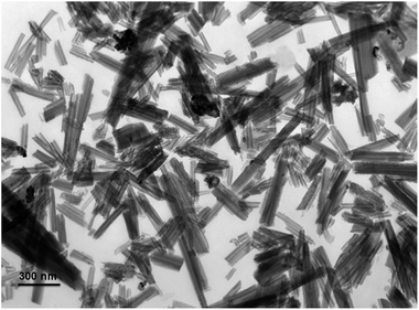
The natural halloysite nanotubes (halloysite nanotubes, SBET = 83.3 m2 g−1, Vpore = 0.33 cm3 g−1) was purchased from Zhengzhou Jinyangguang Chinaware Co. Ltd., Henan, China. The morphology of halloysite nanotubes was characterized by TEM analysis. Fig. 1 reveals that the natural halloysite clay possesses a hollow tubular structure with an open-ended lumen along the nanotubes. Concerning the high reaction temperature for SCRM process, the halloysite derived silica–alumina composite oxides were prepared by the calcination process. Typically, prior to use, the halloysite nanotubes were purified by refluxing with HNO3.52 The purchased halloysite nanotubes were firstly milled and sieved, then 20 g of halloysite nanotubes were treated with 150 mL 3.0 M HNO3 at 80 °C with constant stirring for 8 h. After being cooled to room temperature, the samples were filtered and washed with deionized water several times until the pH was neutral. After that, the halloysite nanotubes were dried at 105 °C for 12 h, and subsequently were calcined at 800 °C for 6.0 h, and the halloysite derived silica–alumina composite oxide support with 800 °C of TC was prepared. By adjusting the calcination temperature, a series of SA–H supports with diverse TC values (900 °C, 1000 °C, and 1100 °C) were synthesized. The traditional silica–alumina composite oxide was prepared by precipitation method (SA-P), which was used for a comparison. Typically, 3.6 g of tetraethyl orthosilicate (TEOS) and 6.5 g of Al(NO3)3·9H2O were dissolved in 100 mL of ethanol, after stirring for 1 h, 20 g of 25 wt% ammonia solution was dropwise added into above solution with rapid stirring. After THE ammonia solution was added, the suspension was stirred for another 5 h. After cooled to ambient temperature, the resulting suspension was filtered and washed with deionized water several times until the pH was neutral. Finally, the obtained powder was dried at 105 °C for 12 h and subsequently calcined at 1000 °C for 6 h in muffle, then the traditional SA-P support was obtained.The supported Ni catalysts (10% of nominal Ni loading) on the SA–H with diverse TC and on the SA-P were prepared by homogeneous deposition–precipitation by using urea as precipitant. Typically, 0.9 g of support powder was suspended in 150 mL of deionized water, and then the 0.5 g of nickel nitrate (Ni(NO3)2·6H2O) and 1.0 g of urea were added into the above suspended solution. After that, the resulting suspension was heated upto 90 °C with vigorously stirring and then kept at this temperature for 10 h. After cooled to room temperature, the suspension was filtered and washed with deionized water several times until the pH became neutral. Finally, the obtained sample was dried at 105 °C for 12 h and subsequently calcined at 800 °C for 6 h in muffle, and then the 10 wt% Ni/SA–H with diverse TC and the 10 wt% Ni/SA-P were obtained.
2.2. Characterization of supports and catalyst
The transmission electron microscopy (TEM) images were obtained by using a Tecnai F30 HRTEM instrument (FEI Corp.) at an acceleration voltage of 300 kV. Nitrogen adsorption–desorption experiments were carried out at −196 °C on a Beishide apparatus of model 3H-2000PS1 system. The specific surface area was calculated by the Brunauer–Emmett–Teller (BET) method, and the pore size distribution was calculated by BJH model from the desorption branch of the isotherms. The XRD patterns were collected from 10 to 90° at a step width of 0.02° using Rigaku Automatic X-ray Diffractometer (D/Max 2400) equipped with a CuKα source (λ = 1.5406 Å). The average crystallite sizes were estimated on the basis of Scherrer formula over the multiple characteristic diffraction peaks by the MDI Jade 5 software. The Ni dispersion of the samples was measured by CO titration at 50 °C using Builder Chemisorption instrument (PCA-1200). The sample (∼100 mg) was reduced in situ with a H2–Ar mixture by heating up to 800 °C at a ramp rate of 10 °C min−1 for 1.0 h, then flushed at 800 °C with Ar for 30 min. After prereduction, the sample was cooled to 50 °C and CO chemisorption was carried out. The total metal dispersion of Ni metal was calculated from eqn (1), where DM, VS, SF, SW, and MW are dispersion of metal (%), volume of active gas chemisorbed (cm3 at STP), stoichiometry factor, sample weight (g), and molecular weight of active metal (g mol−1), respectively:
 | (1) |
H2-TPR experiments were performed in Builder Chemisorption instrument (PCA-1200). 50 mg of catalyst pretreated in Ar (30 mL min−1) at 300 °C for 30 min and then was cooled down to ambient temperature in Ar. After that, the sample was reduced with a 10 vol% H2–Ar mixture (30 mL min−1) by heating up to 800 °C at a ramp rate of 10 °C min−1. The TGA analysis was conducted to study the amount of coke deposited on the spent Ni/SANR–H and Ni/SA-P catalysts using a Perkin-Elmer STA 6000 with a heating rate of 10 °C min−1 from 30 to 800 °C in an air stream.
2.3. Catalytic performance measurement
The catalytic performance measurement of the prepared catalysts was performed in a quartz tube fixed-bed continuous reactor (6 mm O.D.) at atmospheric pressure. Typically, 50 mg of catalyst with the 60–80 mesh particle size was loaded between two quartz wool plugs. The temperatures were measured by using K-type thermocouples and controlled by a PID controller. Before the reaction, the catalyst was reduced at 800 °C for 1 h under the mixture of 20% H2 in N2 at a flow rate of 30 mL min−1. The reaction feed contained the CH4, CO2, H2O, and N2 (N2 was used as internal standard gas, CH4![[thin space (1/6-em)]](https://www.rsc.org/images/entities/char_2009.gif) :
:![[thin space (1/6-em)]](https://www.rsc.org/images/entities/char_2009.gif) CO2
CO2![[thin space (1/6-em)]](https://www.rsc.org/images/entities/char_2009.gif) :
:![[thin space (1/6-em)]](https://www.rsc.org/images/entities/char_2009.gif) H2O
H2O![[thin space (1/6-em)]](https://www.rsc.org/images/entities/char_2009.gif) :
:![[thin space (1/6-em)]](https://www.rsc.org/images/entities/char_2009.gif) N2 = 1
N2 = 1![[thin space (1/6-em)]](https://www.rsc.org/images/entities/char_2009.gif) :
:![[thin space (1/6-em)]](https://www.rsc.org/images/entities/char_2009.gif) 0.4
0.4![[thin space (1/6-em)]](https://www.rsc.org/images/entities/char_2009.gif) :
:![[thin space (1/6-em)]](https://www.rsc.org/images/entities/char_2009.gif) 0.8
0.8![[thin space (1/6-em)]](https://www.rsc.org/images/entities/char_2009.gif) :
:![[thin space (1/6-em)]](https://www.rsc.org/images/entities/char_2009.gif) 1.2) at 40 mL min−1 of the total flow rate (gas hourly space velocity, GHSV, 48
1.2) at 40 mL min−1 of the total flow rate (gas hourly space velocity, GHSV, 48![[thin space (1/6-em)]](https://www.rsc.org/images/entities/char_2009.gif) 000 mL g−1 h−1), which was controlled by the mass flow controllers. The reforming reaction was performed at 700 °C, and the N2 was used an internal standard to calculate the CH4 and CO2 conversions. The effluent gas was passed through a trap to condense the residual steam and then analyzed by using a gas chromatograph online with a molecular sieve column and a Porapaq Q column.
000 mL g−1 h−1), which was controlled by the mass flow controllers. The reforming reaction was performed at 700 °C, and the N2 was used an internal standard to calculate the CH4 and CO2 conversions. The effluent gas was passed through a trap to condense the residual steam and then analyzed by using a gas chromatograph online with a molecular sieve column and a Porapaq Q column.
The CH4 conversion, CO2 conversion, CO selectivity, and H2 selectivity (eqn (2)−(5)) were calculated on the basis of the following equations. Where, FCH4,in, FCO2,in, and FH2O,in are the flow rate of each component (CH4, CO2, and H2O, respectively) in the feed; the FCH4,out, FCO2,out, and FH2O,out, FH2,out, and FCO,out are the flow rate of each component (CH4, CO2, H2O, H2, and CO, respectively) in the effluent. In eqn (4) for H2 selectivity, the section of FH20,in–FH2O,out is denoted as the produced hydrogen by the steam reforming of methane, which was actually calculated on the basis of the transformed CH4 in steam reforming reaction. On the basis of the amount of transformed CO2, the transformed CH4 in dry reforming reaction can be calculated. The transformed CH4 in steam reforming reaction can be calculated by the total transformed CH4 minus the transformed CH4 in dry reforming reaction. That is to say, although the steam was not analyzed by GC, the section of FH20,in–FH2O,out can be indirectly calculated by the combination of FCH4,in, FCO2,in, FCH4,out, and FCO2,out.
CH4 conversion:
 | (2) |
CO2 conversion:
 | (3) |
H2 selectivity:
 | (4) |
CO selectivity:
 | (5) |
3. Results and discussion
3.1. Characterization of the as-prepared SA–H supports
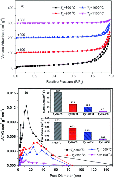
Fig. 2 presents N2 adsorption–desorption isotherms and pore size distributions from desorption branch of SAH supports with diverse preparation temperatures. From Fig. 2(a), N2 adsorption–desorption isotherms of silica–alumina composite oxide with diverse preparation temperatures belong to type IV with H3 hysteresis loops. Fig. 2(b) shows three primary pore populations, appeared around approximately 3.8 nm, 9.3–13 nm, and 20–40 nm. The 3.8 nm mesopores might be attributed the newly formed mesopores during dehydration of tubular halloysite.51 The 9.3–13 nm mesopores might be identified as the lumens of halloysite. The 20–40 nm mesopores might be assigned to interparticular porosity between particles in bundles.53 The pore volume of all the three kinds of mesopores decreased as the increase of calcination temperature, which may be ascribed to the possible progressively collapse of the tubular structure during these calcination processes. Inset in Fig. 2(b) is BET specific surface (SBET) and total pore volume (Vtotal) of SA–H supports prepared with diverse TC values. The decreased SBET and Vtotal as the increase of also demonstrate the possible progressively collapse of the tubular structure of halloysite.51In order to confirm the possible progressively collapse of the tubular structure of halloysite as the increase of TC, TEM analysis was carried out. Fig. 3 shows the typical TEM images of SA–H supports (TC = 800 °C and 1000 °C). From Fig. 3(a), the silica–alumina composite oxide prepared at 800 °C basically remains the tubular morphology, while, visible collapse could be observed in comparison with the raw halloysite (Fig. 1). From Fig. 3(b), the substantial changes could be observed in morphology and the tubular structure of halloysite is completely collapsed. The halloysite derived silica–alumina nanorod (SANR–H) can be obtained. The significant decrease in specific surface area and pore volume of the SA–H with 1000 °C of TC in comparison with the one with 800 °C of TC from the N2 adsorption–desorption results shown in Fig. 2 presents a further evidence for the change in morphology led by higher calcination temperature, owing to the resulting collapse of halloysite. The change in the morphology and textural properties of the as-prepared SA–H supports led by the different calcination temperatures may strongly affect the nature of the supported Ni catalysts on SA–H, which subsequently affects the catalytic performance of the Ni/SA–H catalysts for SCRM reaction.
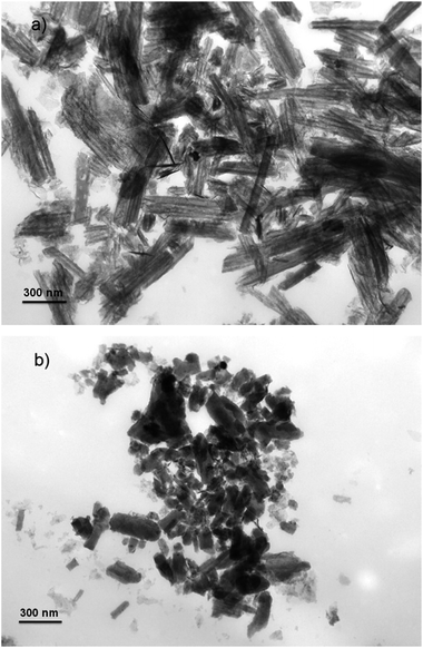 | ||
| Fig. 3 TEM images of as-prepared silica–alumina composite oxides derived from natural halloysite through calcination with different temperatures. (a) TC = 800 °C and (b) TC = 1000 °C. | ||
3.2. Characterization of Ni/SA–H catalysts
The N2 adsorption–desorption, XRD, and CO chemisorption experiments were performed to explore the effect of morphology and textural properties led by TC on the nature of supported Ni catalysts. The results for specific surface area and total pore volume of the Ni/SA–H catalysts with diverse TC values are listed in Table 1. It is understandable that the specific surface area and total pore volume sequentially decreases as the TC rises from 800 to 1100 °C. Correlated to the results in Fig. 2, the increased specific surface area and total pore volume can be obtained after supporting Ni on SA–H supports, which may be ascribed to the possible formation of accumulating pores on the supports in the process of Ni precipitation process.| TC (°C) | SBETa (m2 g−1) | Vtotalb (cm3 g−1) | DNic (nm) | Ni dispersityd (%) |
|---|---|---|---|---|
| a BET specific surface area from N2 adsorption–desorption.b Total pore volume.c Average crystallite size of metallic Ni calculated from the Scherrer equation according to the characteristic peaks toward the Ni (111) plane.d Ni dispersity from CO chemisorption calculated on the basis of eqn (1). | ||||
| 800 | 98.3 | 0.45 | 14.7 | 0.17 |
| 900 | 44.0 | 0.23 | 13.8 | 0.27 |
| 1000 | 31.3 | 0.19 | 9.2 | 0.60 |
| 1100 | 10.8 | 0.08 | 14.9 | — |
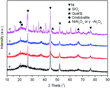
XRD patterns of reduced Ni/SA–H catalysts with diverse TC for the preparation process of SA–H supports are demonstrated in Fig. 4. The average crystalline size of Ni estimated based on the full width at half maximum (FWHM) of Ni (111) plane by the Scherrer equation and Ni dispersity by CO chemisorption are presented in Table 1. From Fig. 4, all samples show the diffraction peaks of impurity quartz and cristobalite.56 The broad reflection centered at approximately 21.1° is attributed to the dissociative amorphous SiO2 that segregated from halloysite calcined at temperature above 600 °C.53,57 Three peaks located at approximately 37.0°, 45.6°, and 66.6° emerged in all the spectrums, which can be attributed to either γ-Al2O3 (JCPDS card no. 10-0425) or NiAl2O4 spinel (JCPDS card no. 10-0339) as the diffraction peaks of these phases are overlapped. Since no γ-Al2O3 might emerge when halloysite undergoes thermal treatment below 950 °C,53,58 above mentioned diffraction peaks of reduced Ni/SA–H catalysts with support calcined at 800 °C and 900 °C should be related to NiAl2O4 spinel. For reduced sample with support calcined at 1000 °C and 1100 °C, the NiAl2O4 spinel phase has a higher possibility to exist owing to the calcination temperature used in the present study.59,60 And the formation of NiAl2O4 spinel under calcination process is essential for the following stability performance of the robust Ni/SA–H catalyst. Furthermore, the typical reflections of metallic Ni phase at 44.4°, 51.7°, and 76.5° are identified (JCPDS no. 03-1051). From Table 1, the average crystalline size of Ni decreases and Ni dispersity increases as the TC for supports preparation increases from 800 °C to 1000 °C, while the average crystalline size of Ni increases and Ni dispersity decreases when the temperature further rises up to 1100 °C. The Ni/SA–H catalyst with 1000 °C of TC owns the smallest average crystalline size of Ni and the highest Ni dispersity, which is favorable for high activity towards SCRM reaction. Moreover, the decreased crystalline size of Ni might efficiently strengthen the interaction between Ni and support, which may improve the catalytic stability of Ni-based catalyst for reforming process by suppressing the Ni sintering and coke deposition.40–43
Moreover, the Ni dispersion of Ni/SA–H catalysts decreases with increasing calcination temperature from 800 to 1000 °C. However, the further increase of calcination temperature results in the decrease of Ni dispersion. From the results for the surface area and pore volume of the as-prepared silica–alumina composite oxides derived from natural halloysite through calcination with diverse temperatures presented in Fig. 2, the increasing calcination temperature leads to obvious decrease in both surface area and pore volume. Especially, as the calcination temperature was increased from 1000 to 1100 °C, the surface area sharply decreases from 17.0 to 4.0 m2 g−1, as well as the pore volume sharply decrease from 0.15 to 0.03 cm3 g−1. The decrease in either surface area or pore volume may worsened the Ni dispersion on the as-synthesized supports. The 4.0 m2 g−1 of such low surface area and the almost disappeared pores of the SA–H prepared at 1100 °C make the Ni accumulate on support, and the Ni dispersity is too low to be determined by CO chemisorption, although the average Ni crystalline size of the supported Ni catalyst on SA–H (1100 °C) is similar to that of the supported Ni catalyst on SA–H (800 °C). However, from Table 1, the increasing Ni dispersity can be observed as the calcination temperature is increased from 800 to 1000 °C, which can be ascribed to the change in the morphology from tubular shape to nanorod, now that the surface area and pore volume also decrease.
3.3. Catalytic performance of Ni/SA–H catalysts for steam-CO2 dual reforming of methane
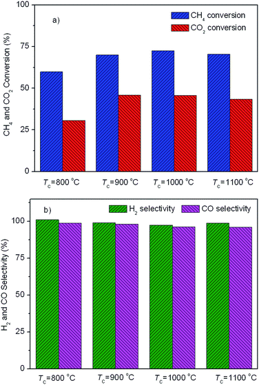
Fig. 5 displays the catalytic activity of the as-prepared Ni/SA–H catalysts for SCRM reaction. From Fig. 5, the catalytic activity of Ni/SA–H catalysts is dependent on the morphology and textural properties of the SA–H supports strongly affected by the calcination temperature for their preparation process. The supported Ni catalyst on the halloysite derived SA–H with nanorod feature prepared by calcination at 1000 °C demonstrates the highest catalytic activity. Correlating the catalytic activity to the nature of catalysts, the catalytic activity of the supported Ni catalysts is directly dependent on Ni dispersity but not on their specific surface area. The higher surface area doesn't lead to higher activity, which is inconsistent with previous report that higher surface results in higher activity.54,55 Although the increasing calcination temperature from 800 to 1000 °C leads to the decrease in surface area and pore volume, the increasing catalytic activity can be observed, which can be ascribed to the change in the morphologies of SA–H supports from tubular shape to nanorod. Moreover, from Fig. 5b, the Ni/SA–H catalysts own the similar H2 and CO selectivity. Moreover, towards all of the as-synthesized catalysts, the H2 selectivity is a little higher than CO selectivity, which is contrary to the previously reported results for the H2 and CO selectivity over the supported Ni catalysts on ZrO2.61 This might be ascribed to the support effect or to the different methods for Ni loading. By using halloysite derived silica–alumina composite oxide as support, the steam reforming of methane might be efficiently enhanced by its abundant surface hydroxyl group. In comparison with our previously results, the developed supported Ni catalyst on SANR–H that is prepared by calcining halloysite at 1000 °C exhibits much higher catalytic activity. It can be considered as a promising candidate for SCRM reaction. Interestingly, although the Ni dispersity of the Ni/SA–H (1100 °C) from CO chemisorption analysis is almost 0%, the supported Ni catalyst on SA–H prepared by calcining at 1100 °C exhibits high initial catalytic activity for this reaction, and the activity is even higher than that of the supported Ni catalyst on the SA–H prepared at 800 °C. In order to reveal this abnormal phenomenon, we did H2-TPR experiments on the supported Ni catalysts on the SA–H prepared with diverse calcination temperatures, and the H2-TPR profiles are presented in Fig. 6. From Fig. 6, the H2-TPR profiles of four supported Ni catalysts present obviously different features. From references,61–64 The peaks appearing below 400 °C can be assigned to the reduction of free NiO. The peaks appearing 400–600 °C and 600–800 °C can be attributed to the reduction of the weak and strong Ni-support interaction. The reduction peak above 800 °C is attributed to the reduction of crystalline NiAl2O4 spinel. From Fig. 6, the increasing calcination temperature leads to the increase in the amount of the free NiO or the one with weak Ni-support interaction. All of NiO for the Ni/SA–H (1100 °C) almost exists in a bulk NiO form, and no Ni-support interaction appears on this sample. This is also an evidence to confirm the almost 0% of Ni dispersity although it has a similar average Ni crystalline size to Ni/SA–H (800 °C). Although the Ni dispersity is very low, the Ni/SA–H (1100 °C) still exhibits higher initial activity than the Ni/SA–H (800 °C), ascribed to the existence of a large amount of free reducible NiO.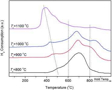 | ||
| Fig. 6 H2-TPR profiles of the as-prepared supported Ni catalysts on the silica–alumina composite oxides derived from natural halloysite through calcination with diverse temperatures. | ||
3.4. Catalytic stability of the developed Ni/SANR–H catalyst
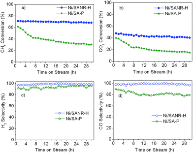
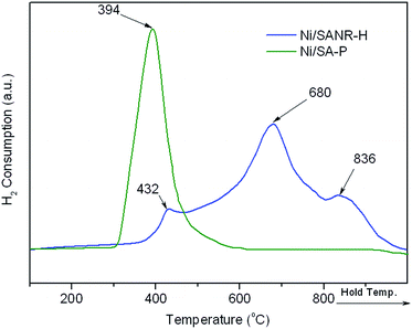
It is generally accepted that the deactivation by coke still is a bottleneck problem for the industrial application of Ni-based catalysts for synthesis gas production from reforming of methane. Therefore, the development of stable and coke-resistant catalysts is of a, important concern. Herein, the long-term stability of the developed Ni/SANR–H catalyst was measured, and the results are displayed in Fig. 7. For comparison, the supported Ni catalyst on the traditional silica–alumina prepared by precipitation (SA-P) was also included. From Fig. 7, the developed Ni/SANR–H catalyst demonstrates the unexpected catalytic stability, and no obvious decrease in the CH4 and CO2 conversions can be observed as the time on stream is extended to 30 h. The much higher catalytic stability of Ni/SANR–H catalyst than that of Ni/SA-P can be observed. The outstanding catalytic activity and stability of Ni/SANR–H catalyst allows it to be a promising candidate for SCRM reaction. Herein, the origin of the much higher stability of Ni/SANR–H catalyst in comparison with Ni/SA-P was investigated by employing various characterization techniques including XRD, H2-TPR, TGA, and TEM.Fig. 8 depicts the XRD patterns of the fresh and spent Ni/SANR–H and Ni/SA-P catalysts. The Ni crystalline phase can be identified based on the three peaks appearing at around 44.4°, 51.7°, and 76.5° (JCPDS no. 03-1051). From Fig. 8, the peaks towards Ni for both of the two spent catalysts are much sharper in comparison with those for the two fresh catalysts, implying the Ni growth in the SCRM process. The average Ni crystalline sizes of the two catalysts are estimated by the Scherrer equation based on Ni (111) plane. The Ni slightly grows from 9.2 to 10.1 nm for Ni/SANR–H catalyst but significant increases from 24.7 to 32.5 nm for Ni/SA-P. The developed Ni/SANR–H catalyst demonstrates much higher Ni-sintering resistance than Ni/SA-P catalyst, which is one reason for the much higher catalytic stability of the former in comparison with the latter. Then H2-TPR experiments were performed to explore the reason for the higher Ni-sintering resistance of Ni/SANR–H than Ni/SA-P. From Fig. 9, the H2-TPR profiles of two catalysts show notably different features. Based on references,61–64 the peaks at temperature lower than 400 °C on the two catalysts is indicative for the reduction of free NiO. The reduction peaks appearing from 600 to 800 °C on the Ni/SANR–H catalyst can be assigned to the reduction of “NiO·Al2O3” (surface NiAl2O4 spinel or defeated NiAl2O4 spinel), and the reduction peak above 800 °C is attributed to the reduction of crystalline NiAl2O4 spinel. However, no reduction peak above 600 °C for Ni/SA-P can be observed. The surface NiAl2O4 spinel and crystalline NiAl2O4 spinel for the developed Ni/SANR–H catalysts show the existence of very strong interaction between Ni species and the support, which is favorable for high Ni-sintering resistance and strong suppression on coke deposition.65,66
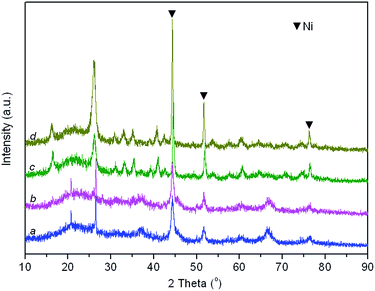 | ||
| Fig. 8 XRD patterns of fresh and spent catalysts. (a) fresh Ni/SANR–H catalyst, (b) spent Ni/SANR–H catalyst, (c) fresh Ni/SA-P catalyst, and (d) spent Ni/SA-P catalyst. | ||
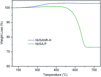
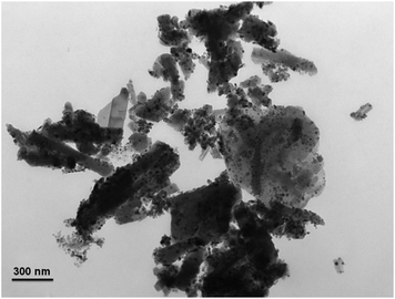
Coke deposition is one of the most important reasons for the deactivation of catalyst in methane reforming. Moreover, the large amount of coke deposition also leads to high pressure drop and the crash of catalysts. Therefore, TGA experiment was carried out to investigate the coke deposition behaviour on both catalysts, and the TGA curves of the two spent catalysts are presented in Fig. 10. From the TGA curves, the weight gain phenomenon in the initial heating stage can be seen on both catalysts, ascribed to the re-oxidation of metallic Ni on the spent catalysts. After the weight gain stage, tremendous difference appears in the weight loss stage on the two curves. For the spent Ni/SANR–H catalyst, no visible weight loss can be observed, indicating the absence of the coke on the spent Ni/SANR–H catalyst. However, the spent Ni/SA-P catalyst shows approximately 27% of weight loss, ascribed to the heavy coke deposition. Generally, visible coke on Ni-based catalysts can be presented for reforming process of methane. However, we cannot see visible weight loss on the TGA curve of the developed Ni/SANR–H catalyst. In order to further confirm this observation, we perform TEM analysis, and Fig. 10 depicts the typical TEM image of the spent Ni/SANR–H catalyst. From Fig. 11, no visible coke on the spent Ni/SANR–H catalyst can be observed, which further verifies the TGA results. From above, the developed Ni/SANR–H catalyst demonstrates unexpected coke resistant capacity in the SCRM process, ascribed to the much stronger Ni-support interaction confirmed by H2-TPR result. This is another important reason for the outstanding catalytic stability for SCRM reaction. The unexpected coke-resistance of Ni catalyst is of great importance for its industrial application for SCRM process.
From above analysis, the stronger Ni-support interaction of Ni/SANR–H catalyst in comparison with that of supported Ni catalyst on traditional silica–alumina composite oxide endows it to exhibit much higher Ni-sintering and coke deposition resistance, which results in its much higher catalytic stability for SCRM reaction. The outstanding catalytic performance of Ni/SANR–H catalyst allows it to be considered as promising candidate for synthesis gas production through SCRM reaction.
4. Conclusions
In summary, the halloysite derived silica–alumina composite oxides with different morphology and textural properties have been prepared by calcination with different temperatures. It has been found that the catalytic performance of the supported Ni catalysts on the as-synthesized SA–H composite oxides is dependent on the Ni dispersity that is significantly affected by the morphology and textural properties of supports. The halloysite derived silica–alumina composite oxide with nanorod feature (SANR–H) prepared by calcination at 1000 °C can be considered as a promising carrier, and the supported Ni catalyst on the SANR–H has demonstrated expected catalytic performance for steam-CO2 dual reforming of methane with outstanding resistance towards both Ni-sintering and coke deposition. In combination of outstanding catalytic performance of the Ni/SANR–H catalyst and the abundance reserves and low cost of halloysite, the developed the Ni/SANR–H can be considered as a promising practical catalyst for steam-CO2 dual reforming of methane for synthesis gas production.Acknowledgements
This work is financially supported by the Joint Fund of Coal, set up by National Natural Science Foundation of China and Shenhua Co., Ltd. (grant no. U1261104), and the National Natural Science Foundation of China (grant no. 21276041), and also sponsored by the Chinese Ministry of Education via the Program for New Century Excellent Talents in University (grant no. N8, 12-14CET-12-0079), the Natural Science Foundation of Liaoning Province (grant no. 2015020200) and the Fundamental Research Funds for the Central Universities (grant no. DUT15LK41).Notes and references
- Y. J. Lee, S. I. Hong and D. J. Moon, Catal. Today, 2011, 174, 31–36 CrossRef CAS.
- H. S. Roh, K. Y. Koo, U. Joshi and W. L. Yoon, Catal. Lett., 2008, 125, 283–288 CrossRef CAS.
- M. Pen, J. Gomez and J. G. A. Fierro, Appl. Catal., A, 1996, 144, 7–57 CrossRef.
- E. F. Sousa-Aguiar, F. B. Noronha and A. Faro Jr, Catal. Sci. Technol., 2011, 1, 698–713 Search PubMed.
- A. C. Koh, L. Chen, W. K. Leong, B. F. Johnson, T. Khimyak and J. Lin, Int. J. Hydrogen Energy, 2007, 32, 725–730 CrossRef CAS.
- S. Rabe, T.-B. Truong and F. Vogel, Appl. Catal., A, 2005, 292, 177–188 CrossRef CAS.
- H. S. Roh, K. W. Jun, W. S. Dong, S. E. Park and Y. S. Baek, Catal. Lett., 2001, 74, 31–36 CrossRef CAS.
- K. Y. Koo, H. S. Roh, Y. T. Seo, D. J. Seo, W. L. Yoon and S. B. Park, Appl. Catal., A, 2008, 340, 183–190 CrossRef CAS.
- K. Y. Koo, H. S. Roh, Y. T. Seo, D. J. Seo, W. L. Yoon and S. B. Park, Int. J. Hydrogen Energy, 2008, 33, 2036–2043 CrossRef CAS.
- H. S. Roh, K. Y. Koo, J. H. Jeong, Y. T. Seo, D. J. Seo, Y. S. Seo, W. L. Yoon and S. B. Park, Catal. Lett., 2007, 117, 85–90 CrossRef CAS.
- Q. H. Zhang, Y. Li and B. Q. Xu, Catal. Today, 2004, 98, 601–605 CrossRef CAS.
- M. Danilova, Z. Fedorova, V. Zaikovskii, A. Porsin, V. Kirillov and T. Krieger, Appl. Catal., B, 2014, 147, 858–863 CrossRef CAS.
- T. H. Gardner, J. J. Spivey, E. L. Kugler and D. Pakhare, Appl. Catal., A, 2013, 455, 129–136 CrossRef CAS.
- S. K. Ryi, S. W. Lee, J. W. Park, D. K. Oh, J. S. Park and S. S. Kim, Catal. Today, 2014, 236, 49–56 CrossRef CAS.
- C. Carrara, J. Munera, E. Lombardo and L. Cornaglia, Top. Catal., 2008, 51, 98–106 CrossRef CAS.
- P. Ferreira-Aparicio, C. Marquez-Alvarez, I. Rodrıguez-Ramos, Y. Schuurman, A. Guerrero-Ruiz and C. Mirodatos, J. Catal., 1999, 184, 202–212 CrossRef CAS.
- J. Kehres, J. G. Jakobsen, J. W. Andreasen, J. B. Wagner, H. Liu, A. Molenbroek, J. Sehested, I. Chorkendorff and T. Vegge, J. Phys. Chem. C, 2012, 116, 21407–21415 CAS.
- K. Sutthiumporn and S. Kawi, Int. J. Hydrogen Energy, 2011, 36, 14435–14446 CrossRef CAS.
- Z. Zhang, X. E. Verykios, S. M. MacDonald and S. Affrossman, J. Phys. Chem., 1996, 100, 744–754 CrossRef CAS.
- D. Li, Y. Nakagawa and K. Tomishige, Appl. Catal., A, 2011, 408, 1–24 CrossRef CAS.
- Ş. Özkara-Aydınoğlu and A. E. Aksoylu, Int. J. Hydrogen Energy, 2011, 36, 2950–2959 CrossRef.
- M. Bradford and M. Vannice, Catal. Rev., 1999, 41, 1–42 CAS.
- C. J. Liu, J. Ye, J. Jiang and Y. Pan, ChemCatChem, 2011, 3, 529–541 CrossRef CAS.
- A. Mishra, N. Galinsky, F. He, E. E. Santiso and F. Li, Catal. Sci. Technol., 2016 10.1039/c5cy02186c.
- L. Xu, J. Zhang, F. Wang, K. Yuan, L. Wang, K. Wu, G. Xu and W. Chen, RSC Adv., 2015, 5, 48256–48268 RSC.
- D. Pakhare, V. Schwartz, V. Abdelsayed, D. Haynes, D. Shekhawat, J. Poston and J. Spivey, J. Catal., 2014, 316, 78–92 CrossRef CAS.
- R. Zanganeh, M. Rezaei and A. Zamaniyan, Int. J. Hydrogen Energy, 2013, 38, 3012–3018 CrossRef CAS.
- L. Xu, H. Song and L. Chou, ACS Catal., 2012, 2, 1331–1342 CrossRef CAS.
- N. Wang, K. Shen, L. Huang, X. Yu, W. Qian and W. Chu, ACS Catal., 2013, 3, 1638–1651 CrossRef CAS.
- N. Wang, K. Shen, X. Yu, W. Qian and W. Chu, Catal. Sci. Technol., 2013, 3, 2278–2287 CAS.
- S. Zhang, S. Muratsugu, N. Ishiguro and M. Tada, ACS Catal., 2013, 3, 1855–1864 CrossRef CAS.
- K. Jabbour, N. El Hassan, A. Davidson, S. Casale and P. Massiani, Catal. Sci. Technol., 2016 10.1039/c6cy00032k.
- J. Ashok and S. Kawi, ACS Catal., 2013, 4, 289–301 CrossRef.
- H. Wu, G. Pantaleo, V. La Parola, A. M. Venezia, X. Collard, C. Aprile and L. F. Liotta, Appl. Catal., B, 2014, 156, 350–361 CrossRef.
- X. You, X. Wang, Y. Ma, J. Liu, W. Liu, X. Xu, H. Peng, C. Li, W. Zhou and P. Yuan, ChemCatChem, 2014, 6, 3377–3386 CrossRef CAS.
- L. Li, L. Zhou, S. Ould-Chikh, D. H. Anjum, M. B. Kanoun, J. Scaranto, M. N. Hedhili, S. Khalid, P. V. Laveille and L. D'Souza, ChemCatChem, 2015, 7, 819–829 CrossRef CAS.
- S. A. Theofanidis, V. V. Galvita, H. Poelman and G. B. Marin, ACS Catal., 2015, 5, 3028–3039 CrossRef CAS.
- X. Tu and J. Whitehead, Appl. Catal., B, 2012, 125, 439–448 CrossRef CAS.
- N. Rahemi, M. Haghighi, A. A. Babaluo, M. F. Jafari and S. Allahyari, Catal. Sci. Technol., 2013, 3, 3183–3191 CAS.
- D. Liu, X. Y. Quek, W. N. E. Cheo, R. Lau, A. Borgna and Y. Yang, J. Catal., 2009, 266, 380–390 CrossRef CAS.
- Y. H. Wang, H. M. Liu and B. Q. Xu, J. Mol. Catal. A: Chem., 2009, 299, 44–52 CrossRef CAS.
- J. L. Ewbank, L. Kovarik, F. Z. Diallo and C. Sievers, Appl. Catal., A, 2015, 494, 57–67 CrossRef CAS.
- F. Wang, L. Xu, J. Zhang, Y. Zhao, H. Li, H. X. Li, K. Wu, G. Q. Xu and W. Chen, Appl. Catal., B, 2016, 180, 511–520 CrossRef CAS.
- C. Aguzzi, P. Cerezo, C. Viseras and C. Caramella, Appl. Clay Sci., 2007, 36, 22–36 CrossRef CAS.
- A. Carrillo and J. Carriazo, Appl. Catal., B, 2015, 164, 443–452 CrossRef CAS.
- D. Fix, D. V. Andreeva, Y. M. Lvov, D. G. Shchukin and H. Möhwald, Adv. Funct. Mater., 2009, 19, 1720–1727 CrossRef CAS.
- G. Liu, F. Kang, B. Li, Z. Huang and X. Chuan, J. Phys. Chem. Solids, 2006, 67, 1186–1189 CrossRef CAS.
- P. Luo, Y. Zhao, B. Zhang, J. Liu, Y. Yang and J. Liu, Water Res., 2010, 44, 1489–1497 CrossRef CAS PubMed.
- Y. M. Lvov, D. G. Shchukin, H. Mohwald and R. R. Price, ACS Nano, 2008, 2, 814–820 CrossRef CAS PubMed.
- N. F. A. Sharif, Z. Mohamad, A. Hassan and M. U. Wahit, J. Polym. Res., 2012, 19, 1–10 CrossRef.
- Z. Zhao, J. Ran, Y. Jiao, W. Li and B. Miao, Appl. Catal., A, 2016, 513, 1–8 CrossRef CAS.
- Y. Zhang, J. Pan, M. Gan, H. Ou, Y. Yan, W. Shi and L. Yu, RSC Adv., 2014, 4, 11664–11672 RSC.
- P. Yuan, D. Tan, F. Annabi-Bergaya, W. Yan, M. Fan, D. Liu and H. He, Clays Clay Miner., 2012, 60, 561–573 CrossRef CAS.
- A. D. Ballarini, S. R. de Miguel, E. L. Jablonski, O. A. Scelza and A. A. Castro, Catal. Today, 2005, 107, 481–486 CrossRef.
- L. Xu, H. Zhao, H. Song and L. Chou, Int. J. Hydrogen Energy, 2012, 37, 7497–7511 CrossRef CAS.
- M. Smith, G. Neal, M. Trigg and J. Drennan, Appl. Magn. Reson., 1993, 4, 157–170 CrossRef CAS.
- S. Kadi, S. Lellou, K. Marouf-Khelifa, J. Schott, I. Gener-Batonneau and A. Khelifa, Microporous Mesoporous Mater., 2012, 158, 47–54 CrossRef CAS.
- H. D. Glass, Am. Mineral., 1954, 39, 193–207 CAS.
- S. M. Morris, P. F. Fulvio and M. Jaroniec, J. Am. Chem. Soc., 2008, 130, 15210–15216 CrossRef CAS PubMed.
- Q. Zhang, T. Wu, P. Zhang, R. Qi, R. Huang, X. Song and L. Gao, RSC Adv., 2014, 4, 51184–51193 RSC.
- W. Z. Li, Z. K. Zhao, F. S. Ding, X. W. Guo and G. R. Wang, ACS Sustainable Chem. Eng., 2015, 3, 3461–3476 CrossRef CAS.
- X. Huang, N. Sun, G. Xue, C. Wang, H. Zhan, N. Zhao, F. Xiao, W. Wei and Y. Sun, RSC Adv., 2015, 5, 21090–21098 RSC.
- M. Zangouei, A. Z. Moghaddam and M. Arasteh, Chem. Eng. Res. Bull., 2010, 14, 97–102 CrossRef CAS.
- X. Huang, G. Xue, C. Wang, N. Zhao, N. Sun, W. Wei and Y. Sun, Catal. Sci. Technol., 2016 10.1039/c5cy01171j.
- T. Wu and S. Li, Chin. J. Catal., 2001, 22, 501–504 CAS.
- L. Zhou, L. Li, N. Wei, J. Li and J. M. Basset, ChemCatChem, 2015, 7, 2508–2516 CrossRef CAS.
| This journal is © The Royal Society of Chemistry 2016 |

