A comprehensive review: electrospinning technique for fabrication and surface modification of membranes for water treatment application
Saikat Sinha Ray
a,
Shiao-Shing Chen
*a,
Chi-Wang Li
b,
Nguyen Cong Nguyen
ac and
Hau Thi Nguyen
ac
aInstitute of Environmental Engineering and Management, National Taipei University of Technology, 1, Sec. 3, Zhongxiao E. Rd, Taipei-10608, Taiwan. E-mail: f10919@ntut.edu.tw
bDepartment of Water Resources and Environmental Engineering, TamKang University, 151 Yingzhuan Road, Tamsui District, New Taipei City 25137, Taiwan, Republic of China
cFaculty of Environment and Natural Resources, Da Lat University, Viet Nam
First published on 8th September 2016
Abstract
In this world of nanotechnology, nanofibrous structures offer specialized features, such as mechanical strength and a large surface area, which makes them attractive for many applications. Their large surface area to volume ratio also makes them highly efficient. Among all the techniques for generating nanofibers, electrospinning is an emerging and efficient process. Additionally, the electrospinning technique allows a uniform pore size, which is considered to be one of the important characteristics of membranes. Therefore, electrospun nanofibrous membranes have been used in water purification applications. Furthermore, the technique is widely utilized for generating membranes for membrane distillation and nanofiltration processes, for the removal of contaminants. However, in this review paper, more emphasis is given to the optimization of specific parameters and the preparation of polymeric solutions for fabricating specialized nanofibrous non-woven membranes, and surface modification for application in water treatment technology. Other issues, such as technology limitations, research challenges, and future perspectives, are also discussed.
1. Introduction
An increase in population and urbanization in the 21st century has led to water scarcity on earth and, simultaneously, a larger amount of waste water has been generated. As the population of the whole world rises dramatically, this could result in a more serious environmental crisis, i.e. water resource pollution, which could lead to serious health problems among human beings.1 As per recent research, there will be almost 9 billion people inhabiting the earth by 2050, and one of the crucial challenges will be how to supply fresh water to this huge population.2 Therefore, the need for technological innovation to enable novel desalination, water reclamation, and water/wastewater treatments cannot be ignored. Recently, nanotechnology combined with nano-engineered membranes has held great potential in advancing water reclamation and wastewater treatment processes.3–7 From this point of view, the electrospinning technique for fabricating nanofibrous membranes has emerged as a versatile technique for generating durable and efficient membranes for future applications. The main focus of this review paper is to develop an efficient electrospun nanofibrous membrane through surface modification. Another aspect of the paper is the exploration of the potential for fabrication of electrospun nanofibrous membranes.1.1 Brief history
Before going into the details of electrospinning techniques, it is important to know the evolution of the concept for electrospun nanofibrous membranes.8 A number of milestones were achieved in developing the electrospinning technique. The term “electrospinning” was coined by Raleigh in 1897.9 The Taylor cone concept was then introduced by Geoffrey Ingram Taylor and his team from 1925–1931.10 Anton Formhals filed the first patent for the electrospinning process in 1934.11 From 1944–2000, around 50 patents were filed based on electrospinning techniques.12 As far as the recent scenario is concerned, the electrospinning process gained more popularity in the 1980's due to interest in nanotechnology.13 Therefore, a great deal of research activity is going on in this area, especially since electrospun nanofibers were found to be relevant to applications including tissue engineering, energy storage, and wastewater treatment. More studies and research work are also focused on upscaling and extending the application areas of electrospun fibers and fibrous materials.141.2 Background
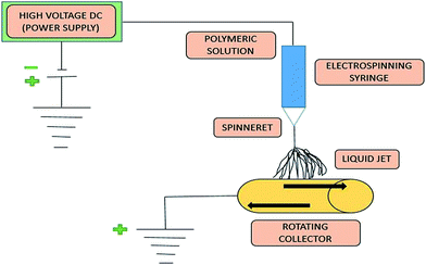
As far as application is concerned, electrospun nanofibrous membranes have become a basis for direct filtration; electrospun polymeric interconnected webs can also be used as a support layer for the new generation and fabrication of thin film composites (TFCs), ultrafiltration (UF)/nanofiltration (NF)/reverse osmosis (RO) membranes and membrane distillation (MD) membranes.15 TFC membranes comprise three fundamental layers, including the top ultrathin selective layer, a middle porous support layer, and a bottom non-woven fabric layer. Recently, the application of electrospun nanofibers as a support layer for TFC membranes has attracted worldwide attention.16 In the past few years, the electrospinning technique has gained much more interest and attention with respect to its application to MD (membrane distillation) membranes.17–20 This review paper will also focus on the recent development of a nanofibrous membrane fabricated by electrospinning for MD application.A schematic block diagram is shown in Fig. 1 to illustrate the electrospinning technique for polymeric solutions. Basically, the set-up consists of three components: (1) a high-voltage supply device, (2) a syringe/capillary tube with needles, and (3) a metal collecting screen/roller.21,22 In the electrospinning technique, a high voltage is used to create an electrically charged jet of polymer solution or melt out of the pipette, so that, just before reaching the collecting screen/roller, the solution jet evaporates and simultaneously solidifies, and is then collected as an interconnected web of small fibers.23,24 During this electrospinning technique, as the intensity of the electric field is increased, the hemispherical surface of the fluid at the tip of the needle/capillary tube elongates to form a conical shape known as the Taylor cone, as previously mentioned.25 Subsequently, the polymer solution discharged from the needle (jet) undergoes elongation, which allows the jet to become very thin and long. Next, the solvent evaporates, and then solidifies as it travels through the air.26,27
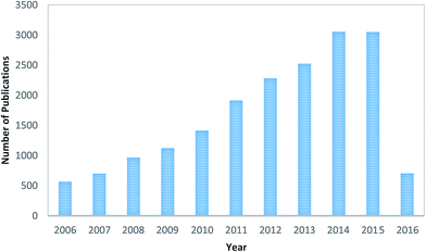
Since the 1990's and especially in recent years, the electrospinning technique, essentially similar to that described by Baumgarten,28 has regained much attention, probably due to the high interest in nanotechnology, as ultrafine fibers or fibrous structures of various polymers with diameters down to submicrons or nanometers can be easily fabricated with this versatile technique (electro + spinning).29 A survey has been done of peer-reviewed publications related to “electrospinning” of the last 10 years, which is shown in Fig. 2. Furthermore, contributions of research work based on the electrospinning technique from different countries, in terms of publications, are shown in Fig. 3; it was found that China is leading the table as per the database of the Scopus search. This database was obtained from the Scopus-based advanced scholar search system. The data clearly indicates that the electrospinning technique has attracted much attention in recent research and the development of membrane technology. As per the database, it is believed that a few hundred polymers are available, of which most can be dissolved in solvents and some can be heated to melting, and finally the electrospinning technique has been used for generating nanofibrous membranes, but only half of them can be found in the open literature as well as the scholar system.29 Furthermore, it has been found that there has been an increase in research on “membrane and wastewater treatment” since the last decade. In this review paper, a systematic analysis is made on the current research and development based on electrospun nanofibrous membranes, including preparation of solutions, study of the structures, characterization, optimization of the parameters, and applications. It is crucial to discuss other issues regarding the limitations, research challenges, and future perspectives of this research topic.
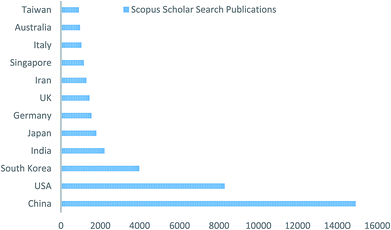 | ||
| Fig. 3 Contribution of different countries to the electrospinning technique (database obtained from Scopus scholar search). | ||
Typically, selectivity is determined by the pore size and pore size distribution across the membrane, such that only particles smaller than the pore size are allowed to pass through it. Fig. 4 shows the size of particles rejected in different membrane processes. The control of pore size, pore size distribution, and mechanical strength is essential for efficient MF (microfiltration), NF (nanofiltration), and UF (ultrafiltration) membranes. Generally, micro-porous membranes are utilized in membrane distillation (MD) processes. Combined with the correct choice of material, electrospinning offers control over these parameters, making electrospun membranes a strong candidate for MD processes.30,31 Typically, in membrane filtration, a solvent is passed through a semi-permeable membrane. The membrane's permeability can be easily determined by the size of the pores, and the membrane acts as a barrier to particulates that are larger than its pores, while the rest of the solvent can pass freely through the membrane. The result is a cleaned and filtered fluid on one side of the membrane, with the removed solute on the other. Thus, it can be concluded that membrane processes depend on selectivity based on pore sizes. Moreover, Fig. 4 also indicates the nominal pore size of different membrane-based processes.
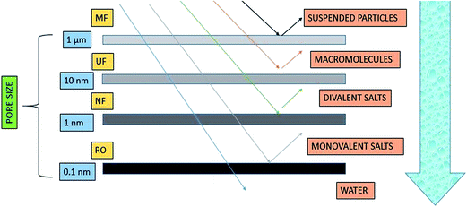 | ||
| Fig. 4 Size of different particulates rejected by various membrane processes.32 | ||
As per Shin et al.,33 the fabrication of desired electrospun nanofibrous membranes depends upon three factors, namely, process parameters, solution parameters, and environmental conditions. Table 1 summarises all the parameters and this is finally discussed in the later part of this paper.
| Process parameters | Solution parameters | Environmental conditions |
|---|---|---|
| Applied potential | Molecular weight | Temperature |
| Electric field strength | Concentration | Humidity |
| Feed rate | Viscosity | Pressure |
| Working distance | Surface tension | Atmospheric composition |
| Electrostatic field shape | Conductivity |
The utilization of electrospun nanofibrous membranes as a support layer for desalination by NF and MD has been well reviewed by Sundarrajan et al.34 Their research group previously reviewed the selectivity of electrospun membranes for air and water filtration applications. Recently, Kaur et al.35 presented a review on electrospun nanofibers, focusing on modifications to membrane characterization methodology as well as post-treatment methods for enhancing their structural integrity. Much research is taking place, and advances are rapidly being made in the preparation and modification of electrospun nanofibrous membranes for water treatment applications. Thus, there is a need to review this research and development in order to explore directions for future studies. In this review paper, we reported on recent advances in the application of electrospun nanofibrous membranes as a barrier layer for waste water treatment, with more emphasis on the reinforcement and post-treatment of electrospun membranes.
2. Comparison of different techniques for membrane fabrication
In this section, various types of membrane fabrication techniques have been discussed. However, the selection of a technique for polymer membrane fabrication depends on the polymer type and the desired structure and application of the membrane. The most commonly used techniques for preparation of polymeric membranes include phase inversion, interfacial polymerization, stretching, track-etching and electrospinning.36 Table 2 describes the methodology and benefits of all the techniques for membrane fabrication.| Membrane fabrication technique | Methodology | Water treatment process & average pore size | Disadvantages | References |
|---|---|---|---|---|
| Phase inversion technique | This is a demixing process whereby the initially homogeneous polymer solution is transformed in a controlled manner from a liquid to a solid state | Reverse osmosis (RO); 3–5 Å | Problems with residual solvent limited range of pore sizes | 37 and 38 |
| Interfacial polymerization | Interfacial polymerization (IP) is the most prominent technique for commercial fabrication of thin-film composite (TFC) RO and NF membranes | Nanofiltration (NF); 0.001–0.01 μm | Residual porogens | 39 and 40 |
| Stretching | This is a solvent-free technique, in which the polymer is heated above the melting point and converted into thin sheet forms, followed by stretching to make it porous in nature | Membrane distillation (MD); 0.1–1 μm | Lack of mechanical strength residual porogens | 41 and 42 |
| Track-etching | In this technique, a nonporous polymeric film is irradiated with energetic heavy ions, leading to the formation of linear damaged tracks across the irradiated polymeric film | Microfiltration (MF); 0.1–10 μm | Problems with residual solvent residual porogens | 43 |
However, there are certain advantages that make the electrospinning technique viable and reliable, as compared to others, for the fabrication of nanofibrous membranes. Thus, Table 3 shows some prominent advantages of the electrospinning technique and it also explains the potential for fabricating desired membranes. Moreover, detailed information will be given regarding techniques and applications based on wastewater treatment.
| Advantages | Description | References |
|---|---|---|
| High surface area to volume ratio | The nano-dimensions of nanofibers provide a high surface area to volume ratio. This makes electrospinning attractive in applications where a large surface area is desirable, such as in membranes | 44 and 45 |
| Variety of polymers and materials utilized | Electrospinning has been used to produce nanofibers from all major classes of materials and polymers | 46 and 47 |
| Low start-up cost | Electrospinning technique setup is generally cheaper. For use in a laboratory, a setup can be self-assembled from off-the-shelf components or else be purchased fully assembled | 48 and 49 |
| Fiber deposition onto other substrates | Electrospun fibers have been successfully deposited on surfaces such as metal, glass, microfibrous mats, and membranes | 50 and 51 |
| Fiber functionalization | Functionalization of electrospun nanofibers can be easily achieved through simple processes, such as blending of polymer solution prior to spinning, post-spinning surface functionalization, or using a core–shell electrospinning setup | 52 and 53 |
| Commercial applications | Air filtration membrane, face mask and water filtration membrane | 54 and 55 |
3. Electrospinning technique
The electrospinning technique is comparatively a versatile technique to fabricate nanofibrous porous membranes for various applications, including filtration, desalination, and wastewater treatment.36,56–583.1 Operation of electrospinning technique
Basically, operation of the electrospinning technique is based upon 4 major steps, which are shown in Fig. 5. This starts from the applied high voltage, and ends with solidification of the jet into fine fibers.In this technique, a high potential (14–16 kV) is applied between the polymer solution droplet and the metal collector. When the electrostatic potential becomes sufficiently high and overcomes the surface tension of the polymer droplet, a charged liquid jet is formed, which usually elongates to form a Taylor cone, as previously mentioned and shown in Fig. 6. The unique features of these fibrous membranes are controllable aspect ratios (aspect ratio = L/d; L—length of the fiber and d—diameter of the fiber), which can be further optimized by changing various parameters, and the morphology of the micro/nanofibrous membrane, which is achieved by varying the polymer solution viscosity, applied electric potential, flow rate of the polymer solution, and environmental conditions.9 The pore size distribution, porosity, hydrophobicity, and surface area of the electrospun membrane are controlled by the fiber diameter and its morphology. Due to the operational control on their fiber size, shape, and morphology, electrospun nanofibrous membranes have been used for wastewater filtration and membrane distillation (MD) processes.59–62 Furthermore, thermal treatment of the electrospun membranes increased their surface roughness. An increase in the surface roughness of the fiber further increases the contact angle to ∼145°, which indicates the high hydrophobicity of the membrane, which can be further used in membrane distillation (MD) processes.36
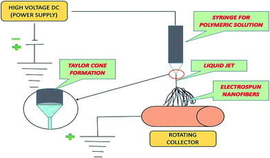 | ||
| Fig. 6 Diagram shows the formation of Taylor cone in electrospinning technique.63 | ||
3.2 Electrospinning parameters
It is very important to understand the electrospinning working parameters, as these may affect fiber morphologies. Typically, there are certain parameters governing the electrospinning process, which are as follows:(1) Solution parameters
(2) Process parameters
(3) Ambient parameters
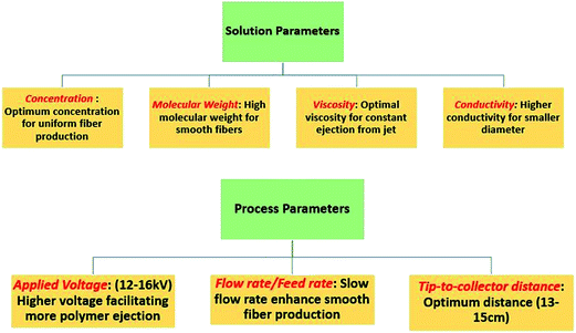
Fig. 7 shows the prominent parameters that may affect the electrospun nanofibrous membranes, along with a brief discussion of the optimal conditions required for running the electrospinning technique for improved performance of the membrane. Typically, working parameters are crucial to understanding not only the nature and optimum conditions of electrospinning, but also the conversion of polymeric solutions into nanofibers through the electrospinning technique. Each of these parameters may affect the quality of the fibers, and by proper control of these parameters, one can fabricate electrospun fibers with desired morphologies and diameters. In Fig. 7, a concise introduction of optimal conditions that may influence the fiber quality and properties is presented.
However, there is another parameter that may affect the properties of electrospun nanofibrous membranes, i.e. the ambient parameter. This includes humidity and temperature, which can affect the fiber diameter and morphology. Increasing the temperature leads to generation of fibers with a decreased diameter, while lower humidity may dry the solvent completely. Also, increased humidity results in the appearance of small pores on the fiber surface. So, optimum conditions must be maintained for better and improved fiber production.64 Thus, Table 4 shows some of the prominent parameters that may influence the electrospinning process. This information may help researchers to optimize the conditions for fabricating a desired membrane.
| Parameters | Influences | References |
|---|---|---|
| Jet initiation | The jet initiation is the total combination of introducing charges to the electrospinning solution and subjecting it to an electric applied field | 65 |
| Applied voltage | As far as applied voltage is concerned, stretching of the solution droplet may increase with a higher applied voltage; however, the high voltage may also lead to faster acceleration towards the substrate collector, due to the increased potential difference, leading to a lower time of flight for the jet to stretch prior to deposition. Thus, this results in a larger fiber diameter | 66 |
| Solution properties | The solution properties that may significantly affect electrospinning are as follows: | 67 |
| (1) Conductivity | ||
| (2) Viscosity | ||
| (3) Surface tension | ||
| (4) Solvent volatility | ||
| Solution feed rate | At the optimum solution feed-rate, the distribution of fiber diameters will be the narrowest and hence any deviation may result in greater fiber diameter spreading | 68 |
| Solution temperature | It is well understood that a higher solution temperature may decrease the viscosity of the solution. Thus, it is expected that the fiber diameter will be reduced with decreased viscosity | 69 |
| Nozzle diameter | An increase in the nozzle diameter eventually increased the fiber diameter, distribution and productivity. This can be due to a higher mass being available for the electro-spinning technique | 70 |
| Salt additives | The incorporation of salt may influence the electrospinning technique/process in the following ways: | 71 |
| (1) Increased stretching of the spinning jet (due to increased conductivity), therefore producing thinner fibers | ||
| (2) Much more consistent distribution of charges may lead to greater fiber uniformity | ||
| (3) Reduction of surface tension of the solution | ||
| (4) Reducing the formation of beads during electrospinning | ||
| Environment | Particularly, the electrospinning process and the physical characteristics of the fibers are affected by the temperature and humidity of the environment, due to its effect on the rate of vaporization of the solvent and solution sensitivity to humidity | 72 |
4. Polymer solution
Typically, preparation of the polymer solution is the most important part of fabricating an electrospun nanofibrous membrane. However, there are certain factors that may influence the electrospun nanofibrous membrane, such as the average molecular weight and concentration of the polymer, and the utilization of a compatible solvent for dissolving the polymer. In this section, the preparation as well as the properties of the polymeric solution will be discussed.4.1 Preparation of polymer solution
The most commonly used polymers that are successfully electrospun into superfine fibers for waste water applications are cited in Table 5. Moreover, different solvents for the preparation of polymer solution are mentioned in the table.| Polymer/average molecular weight | Solvent | Reference |
|---|---|---|
Polyacrylonitrile, PAN (Mw-150![[thin space (1/6-em)]](https://www.rsc.org/images/entities/char_2009.gif) 000) 000) |
Dimethyl formamide | 73 |
Polyvinyl alcohol, PVA (Mw-177![[thin space (1/6-em)]](https://www.rsc.org/images/entities/char_2009.gif) 000) 000) |
Distilled water | 54 |
Polylactic acid, PLA (Mw-109![[thin space (1/6-em)]](https://www.rsc.org/images/entities/char_2009.gif) 000) 000) |
Dimethyl formamide | 74 |
| Polymethylmethacrylate (PMMA)/tetrahydroperfluorooctylacrylate (TAN) | Dimethyl formamide![[thin space (1/6-em)]](https://www.rsc.org/images/entities/char_2009.gif) : :![[thin space (1/6-em)]](https://www.rsc.org/images/entities/char_2009.gif) toluene (1 toluene (1![[thin space (1/6-em)]](https://www.rsc.org/images/entities/char_2009.gif) : :![[thin space (1/6-em)]](https://www.rsc.org/images/entities/char_2009.gif) 9) 9) |
75 |
Polyethylene oxide, PEO (Mw-400![[thin space (1/6-em)]](https://www.rsc.org/images/entities/char_2009.gif) 000) 000) |
Distilled water | 65 |
Poly(vinylidene fluoride), PVDF (Mw-107![[thin space (1/6-em)]](https://www.rsc.org/images/entities/char_2009.gif) 000) 000) |
DMAc, DMF, NMP, tetrahydrofuran (THF), dimethylsulfoxide (DMSO) | 76 |
However, in the next section, the relationship between the concentration of polymeric solution and the fiber diameter distribution and fiber quality will be discussed. In most of the polymeric electrospun nanofibers, it was found that there was a sharp increase in the fiber diameter when the concentration of the polymer increased. However, the quality of fibers decreases as the concentration declines. Table 6 indicates the effect of the concentration of the polymeric solution on the fiber diameter.
4.2 Properties of polymeric solution
A recent study reveals that the membrane characteristics are highly dependent on the chemical and physical properties of the solution. So, the selection of the proper polymer depends on the following properties:(1) Conductivity
(2) Viscosity
(3) Solvent volatility
(4) Surface tension properties
It has been seen that increasing the conductivity of the solution improves the quality of the fibers. Using near-field electrospinning79 showed that, as the conductivity increases, the deposited fibers change from beaded to straight to curly. The transition from straight fibers to curly may be evidence that the electrospinning jet speed increases with higher conductivity.
For the preparation of the polymer solution for electrospinning, it is required to evaluate whether the solution has sufficient viscosity to be stretched into fibers or not. The entanglement number for the polymeric solution may be used to evaluate the formation of fibers in electrospinning, where the entanglement number can be mathematically denoted as:
Previously, a study showed that, where ne is more than 3.5, smooth fibers were formed for polystyrene, polylactic acid, and polyethylene oxide dissolved in the corresponding proper solvent. However, below 3.5, a mixture of beads and fibers is produced and below 2, no fibers were formed.80
5. Electrospun membrane fabrication procedures
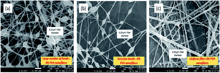
Recently, electrospun membranes were successfully fabricated by surface modification or by incorporating chemical groups in the polymeric solution. Before going into the details of fabrication of electrospun nanofibrous membranes, a study of the morphology is one of the crucial steps. The morphology of the electrospun nanofibrous membrane can be easily analysed by using microscopy, such as scanning electron microscopy (SEM) and transmission electron microscopy (TEM). In addition to that, the fiber diameter distribution and average fiber diameter can be easily measured using software (ImageJ). Thus, SEM images of PVA nanofibers have been shown, where the fiber diameter and quality changes as the concentration of PVA solution is increased. Typically, the optimum concentration should be maintained as a lower concentration may lead to ejection of droplets and substantial bead formation, whereas a higher concentration results in a high solution viscosity, which could mean that the electrical charges cannot generate sufficient strength to stretch the solution to form fibers. The SEM micrographs in Fig. 8 demonstrate the effect of concentration on the quality of fibers. Furthermore, Wang et al.84 investigated the capability of a hybrid polyacrylonitrile (PAN)/PET electrospun nanofibrous membrane for microfiltration. It has been shown that hybrid electrospun nanofibrous membrane could reject microbes like E. coli and produce high flux. In the next section, more relevant discussion has been provided based on hybrid electrospun nanofibers for waste water treatment application.The scanning electron microscopy images not only analyse the morphology; they also indicate the diameter distribution of the superfine fibers. However, the average diameter and the diameter distribution can be obtained by using a custom code image analysis program to analyse the SEM images.85 In this part, various types of fabrication and surface modification techniques will be discussed in detail, which may enhance future research work in water purification technology.
5.1 Functionalization of electrospun fibrous membrane
Typically, functionalization allows the incorporation of other properties into a (single) material nanofibrous membrane. However, a material with improved mechanical properties and chemical stability may be doped with other desirable characteristics, such as anti-microbial, biocompatibility, catalytic, or chemical sensing. Thus, the ability to incorporate another functional property into the nanofiber will significantly enhance the performance and versatility for specific applications. As shown in Table 7, there are two prominent methods of functionalization of electrospun fibrous membranes with varying degrees of versatility.| Method of functionalization | Reactive/functional group | Material chemical group | Location of functionalization | Improved mechanical strength |
|---|---|---|---|---|
| a Note: reactive or functional groups are represented as carboxyl or amino groups, which are utilized for further bonding of other molecules, whereas a material chemical group is represented as the addition of a secondary group to the principal fibrous material. | ||||
| Multi-component electrospinning | Yes | Yes | Surface/core | Yes |
| Mineralization | Yes | — | Surface | Yes |
5.2 Layer-by-layer method
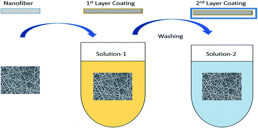
In recent years, chemical blending or coating of functional molecules into/onto the polymers were significantly developed by attempting some new techniques, such as self-assembly and the layer-by-layer method. The layer-by-layer technique is based on the adhesion of both positively and negatively charged macromolecules on the surface of the material. This technique especially makes it much more convenient to physically immobilize some charged molecules on the polymer surface. Fig. 9 illustrates the layer-by-layer method and shows how it can be utilized for fabricating various membranes for membrane-based processes.Recently, it was found that cellulose acetate, with its negatively charged surface, is an attractive material for this purpose. Alternatively, the incorporation of oppositely charged macro-molecules is used to build up the layers. Subsequently, charged organic as well as inorganic molecules have been incorporated into electrospun nanofibrous material.
Basically, the advantage of this technique is that the layers of functional molecules incorporated can be selected either to enhance a single feature or to introduce multiple properties. The high surface area of electrospun nanofibrous membranes has prompted many researchers to explore the possibility of fabricating highly versatile membranes using the layer-by-layer assembly technique.86,87 The incorporation of nanoparticles on the surface of the fiber has been shown to increase its surface roughness and, subsequently, a final layer of fluoroalkylsilane was used to fabricate a superhydrophobic membrane.88 Mostly, the layer-by-layer coating is achieved by the use of oppositely charged organic molecules; however, positively charged inorganic nanoparticles may also be incorporated on negatively charged organic molecules.
5.3 Surface adhesion by electrospraying technique
Surface adhesion originates from secondary forces, such as hydrogen bonding and van der Waals forces, or through partial melting of deposited particles onto the nanofiber surface of the membrane. However, the simplest form of surface adhesion involves dipping the electrospun fibers into a particular solution or suspension of conductive material, such that the conductive material becomes attached to the surface of the fibers. However, simultaneous electrospinning and electrospraying can be used to incorporate nanoparticles on the surface of the nanofibrous membrane. In this case, the sprayer may be directed at the electrospinning jet, such that the particles adhere onto the surface of the fiber prior to deposition on the collector substrate or at the opposite side of a rotating collector. Recent research and development reveals that any type of nanoparticle can be introduced onto the surface of nanofibers using this method. Titanium dioxide (TiO2), magnesium oxide (MgO), and aluminium oxide (Al2O3) nanoparticles have been coated uniformly across the thickness of the membrane using the simultaneous electrospinning and electrospraying technique.895.4 Solution blending process
The solution blending process is probably the most commonly used and simplest method for introducing alternative properties or functions to the core material. This method involves the mixing of two parts in a solution followed by electrospinning, for which only one part of the solution is required to be electrospinnable. There are three possible solution blending processes that are commonly encountered; the first process is where the materials for mixing are soluble in a common solvent, the second is where there is no common solvent to dissolve both materials, and the third is where one material is insoluble.90However, a major drawback is the potential leaching of the added material, since there is no chemical bonding between this and the base. But, if the material is lost very slowly or if the amount is insignificant, the benefits may overcome the loss/drawbacks of this technique.
5.5 Wet chemical treatment technique
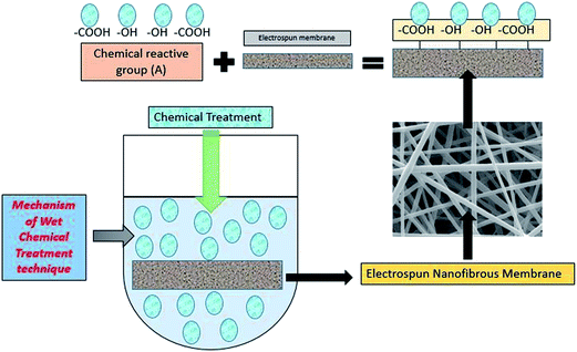
Typically, in wet chemical treatment, the inert polymer nanofiber is treated with a chemical reagent to introduce reactive/functional groups, such as carboxylic, amine or hydroxyl, depending on the presence of sites compatible to electrophilic or nucleophilic attack on the polymeric molecules. Thus, the nanofiber is soaked in an alkaline medium, which is often used to generate carboxylic and/or hydroxyl groups on the nanofiber surface. A cross-linking or bonding agent, such as glutaraldehyde or 1-ethyl-3-(3-dimethylaminopropyl) carbodiimide hydrochloride, can also be used for attachment of molecules onto the nanofiber surface.91 A typical diagrammatic representation of wet chemical treatment, which can be used for the functionalization of electrospun fibrous membrane, is shown in Fig. 10.The zeta potential is found to be another crucial property for analysing the membrane surface chemistry. For instance, membranes with a negative zeta potential repulse negatively charged particles and macromolecules. In order to analyse a fibre's surface charge, the zeta potential is often evaluated by streaming potential measurements as a function of pH. These properties are generated by the electrochemical double layer (EDL), which exists at the phase boundary between a solid and a solution containing ionic moieties. Typically, the zeta potential indicates the electro-kinetic properties at that position of the solid/liquid interface, which is accessible for interactions. Moreover, the zeta potential indicates the fouling tendency of the membrane, based on electrostatic interactions.92
6. Water treatment application by electrospun membrane
Recently, much more attention has been given to the membrane distillation (MD) process, especially for desalination, water reclamation and water/wastewater treatment purposes, but unfortunately this method has not yet been utilized on an industrial scale. The most crucial reason for not introducing this on a large scale is the lack of novel and specific membranes for the membrane distillation (MD) process.93,94 However, before examining the details of wastewater treatment applications, the criteria for the membrane selection must be emphasised.6.1 Criteria for membrane selection
To ensure the efficiency of the filtration process, the selection of a suitable membrane is essential. There are some key parameters related to the membrane, which are dependent on the characteristics of the feed stream used in the system. Primarily, this depends upon the pore size, porosity, surface energy, and also on the nature of the membrane, whether it is hydrophobic or hydrophilic. Fig. 11 shows a typical flowchart of the selection of a proper membrane for further application in waste-water treatment. However, chemical compatibility, pore size, and contact angle are considered to be the primary criteria for selecting membranes for application.When a liquid is dropped on a solid surface, two extreme cases are considered, while measuring the contact angle. The contact angle ranges from 0° to 180°. If the droplet is strongly attached to a hydrophilic solid, the liquid is completely spread out on the solid surface, and the contact angle is equal to 0–30°, or a liquid film is formed on the solid surface, (means highly hydrophilic).97 However, less hydrophilic solids will have a contact angle of about 90°. On the other hand, if the droplet is weakly attached to the solid surface, the contact angle will be above 120°, or the liquid forms a sphere on the solid surface, which may be referred as highly hydrophobic. For better performance of a membrane based on contact angle, Table 8 summarises the variation in contact angle with hydrophobicity/hydrophilicity.97,98
| Contact angle | Nature | Surface energy | Effect | Application |
|---|---|---|---|---|
| 0–30° | Highly hydrophilic | Increases | Water droplet spreads out and finally permeates | — |
| ≥90° | Hydrophilic | Increases | Water droplet spread out only | FO-membrane |
| 90–120° | Hydrophobic | Decreases | Water droplet beads up | MD-membrane |
| ≤120° | Highly hydrophobic | Decreases | Water droplet in spherical form (repelled) | MD membrane |
| Membrane pore size | Removal/retain | Application | References |
|---|---|---|---|
| 0.1 μm to 0.01 μm | Proteins, endotoxins, viruses and silica | Ultrafiltration (UF) | 102 |
| 0.001 μm to 0.01 μm | Multivalent ions, synthetic dyes, sugars and specific salts | Nanofiltration (NF) | 103 |
| 0.0001 μm to 0.001 μm | Mostly all molecules (except water) | Reverse osmosis (RO) | 104 |
Nevertheless, most of the membranes used for membrane distillation (MD) are commercially fabricated for membrane filtration (MF: microfiltration) applications and made up of hydrophobic polymers. In this regard, electrospun nanofibrous membranes have shown convincing features that can be used in a membrane distillation (MD) process.32 Nanofibrous membranes can be used in membrane distillation directly, as the nanofibrous mats generally exhibit a high surface hydrophobicity.
| Membrane | Membrane category | Thickness (μm) | Specific surface area ×107 m−1 | Porosity (%) |
|---|---|---|---|---|
| CA | Electrospun membrane | 406 | 2.020 | 87 |
| Filter paper | Commercial membrane | 79 | 0.025 | 48 |
Surface roughness is another secondary factor that can be considered for membrane selection criteria. An increase in surface roughness influences the hydrophobicity characteristics of the membrane. Recently, it was shown that a PVDF/G (incorporated graphene) electrospun nanofibrous membrane had a higher surface roughness as compared to PVDF nanofibers. A higher surface roughness influences the hydrophobicity of the membrane by increasing the contact angle to around 150°.108
Typically, these were investigated for water filtration application only in the 2000's. Nevertheless, many studies have demonstrated the feasibility and selectivity of electrospun membranes as stand-alone filtration materials. Various materials [e.g. polyethersulfone (PES), cellulose, and polyvinylidene fluoride (PVDF)] commonly used for water filtration membranes have been electrospun to form non-woven nanofibrous membranes. However, the requirements of the electrospun membrane depend on the targeted liquid filtration application.109
However, in this review paper, a thorough study has been presented based on some crucial wastewater treatment techniques and it has been shown how electrospun membranes play a key role in water purification technology.
6.2 Desalination
Desalination is an effective process for overcoming the higher demand for water worldwide. Various desalination technologies have emerged, which include reverse osmosis (RO), membrane distillation (MD), freeze desalination (FD), ion exchange and nanofiltration (NF). Nanofibrous membranes are currently being investigated as potential membranes for desalination due to their improved flux.109–111Previously, the conventional middle layer has been replaced with electrospun nanofibrous membranes; it was then coated with different layers and, finally, thin film nanocomposite (TFNC) membranes were formed.112 It has been observed that the flux rate and oil rejection percentage (oil in water emulsion) of the TFNC membranes were higher than those for commercially available NF membranes.113 For a better performance of electrospun nanofibrous membranes as direct filtration media, electrospun polymeric membranes can be easily utilized as a support layer for the next generation of thin film composite (TFC) (UF/NF/RO) membranes. Thin film composite (TFC) membranes comprise three fundamental layers, which include the top ultra-thin selective layer, the middle porous support layer, and finally the bottom nonwoven fabric layer.16 Recently, the application of electrospun fibers as the support layer of TFC membranes has attracted worldwide attention.
Recently, Su, Shih et al.115 demonstrated the efficiency of electrospun membranes in terms of salt rejection%. Table 11 shows the salt rejection% of desalination. The data indicates the salt rejection of PVDF-co-HFP (HFP: hexafluoropropylene) and the PVDF electrospun membrane was found to give 99.9901% and 99.9888%. The salt rejection of PTFE was evaluated as 99.9951%. The salt rejection of PVDF-co-HFP was better than that of the PVDF electrospun membrane, and was almost the same as that of the PTFE commercial membrane.115
| Membrane | Categories | Salt rejection% |
|---|---|---|
| PVDF-co-HFP | Electrospun membrane | 99.99% |
| PVDF | Electrospun membrane | 99.98% |
| PTFE | Commercial | 99.99% |
When an electrospun membrane is used in membrane distillation, it should be able to maintain separation between the feed and permeate. Therefore, a super-hydrophobic membrane is preferred as it is considered best for maintaining water separation. In recent research, beaded fibers were shown to exhibit higher water contact angles compared to a smooth fibrous membrane. The electrospun poly(vinylidene fluoride) (PVDF) nanofibrous membrane is commonly analysed for water filtration efficiency. The authors have116 investigated the properties of PVDF from beaded to smooth fibers for the purpose of the membrane distillation (MD) process. However, beaded fibers showed a higher water contact angle, while the flux from smooth fibers was better than that from beaded fibers, which may be because of the smaller void volume fraction of beaded fibers.
Typically, a drawback of electrospun membranes is their low liquid entry pressure of water, which may result in pore wetting over time. In order to overcome this issue of pore wetting, Prince et al.117 used a triple-layer membrane consisting of a hydrophilic nanofiber base (alongside with the permeate), a cast membrane middle layer, and an electrospun PVDF top layer (alongside with the feed).117 As far as the MD process is concerned, especially for desalination and wastewater treatment applications, this technique has not yet been utilized on an industrial scale. The most prominent reason for this is the lack of novel and specific membranes for MD applications. The membranes utilized in the MD process must ensure some important specifications before they can be used, e.g. they must be hydrophobic in nature, highly porous, have a high liquid entry pressure (LEP), good thermal/chemical/mechanical stability, and durability.94
Recently, a new concept has been introduced of a three-tier composite membrane by K. Yoon et al.,118 containing a ‘nonporous’ hydrophilic coating that is water permeable (chitosan), an electrospun nanofibrous support (PAN), and a non-woven microfibrous substrate (PET). This concept is systematically represented in Fig. 12. The applied fabricated membrane seems to be efficient in ultrafiltration techniques because of high water flux and low membrane fouling in nature.118
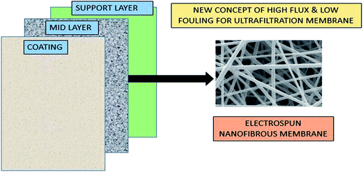 | ||
| Fig. 12 Three-tier concept to fabricate high flux and low-fouling ultrafiltration membrane. [Note: plotted and modified by taking the figure from ref. 118.] | ||
The ultrafiltration membrane may be fabricated by cast-coating with the separation material on the electrospun membrane. Wang et al.113 used electrospinning to fabricate a polyvinyl alcohol (PVA) base substrate, followed by cross-linking to improve the structural stability and mechanical strength of the membrane.113
Quantification of pore size and pore size distribution is one of the critical factors in assessing the rejection% from feed water. In other words, the pore size distribution indicates whether a membrane has the potential to remove microorganisms/heavy metals/particulates/chemicals from the feed stream. However, there is another criterion based on the surface charge of the membrane and the charge distribution of the feed stream. For instance, when negatively charged membranes are used for the rejection of negatively charged molecules, charge interactions between the membrane and solute may play a major role in solute rejection. Therefore, the nominal molecular weight cut-off (MWCO) of a membrane under these conditions is no longer an indicator of solute rejection. Typically, nominal MWCO values of various membranes are provided by the manufacturers, which are generally calculated by rejection tests with a PEG with an average relative molecular mass.119 In Fig. 13, various membranes have been differentiated in terms of rejection%, where this clearly indicates the higher salt rejection% of electrospun mid layer PAN: polyacrylonitrile (3 tier membrane) as compared to commercial NF fiber and PAN membranes.
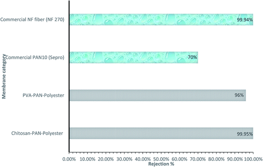 | ||
| Fig. 13 Comparative study of rejection% of various membranes. [Note: mid layer of 3 tier membrane system is PAN (electrospun membrane), feed solution: mixture of vegetable oil (1350 ppm), surfactant (150 ppm, Dow Corning 193 fluid) and deionized water. Plotted the figure by using the data.118] | ||
Beyond rejection%, flux is another crucial criterion for its application. Yoon et al.118 demonstrated that after 24 h operation, the permeate flux for the electrospun-based membrane remains stable, whereas a commercial ultrafiltration membrane (PAN 10) experiences severe flux decline. Table 12 shows a comparative flux study of various membranes, where it has been observed that the flux for the electrospun-based membrane is twelve times higher than that of the commercial membrane.118
| Membrane | Membrane category | Feed solution material | Flux (LMH per psi) |
|---|---|---|---|
| Chitosan coating, electrospun PAN mid-layer and nonwoven polyester | 3 tier membrane | Deionized water | 1.3 |
| Polyvinyl (PVA) alcohol coating, electrospun PAN mid-layer and nonwoven polyester | 3 tier membrane | 100k–200k dextran | 28.5 |
| PAN 10 (Sepro) | Commercial | 100k–200k dextran | 3.94 |
| NF fiber (NF 270) | Commercial | Deionized water | 0.6 |
6.3 Ion exchange membrane
The use of electrospun nanofibers in ion exchange is still emerging. As per the study, polystyrene nanofibers were able to achieve a maximum ion-exchange capacity of 3.74 mmol g−1.121 It has been found that these are comparable with commercially available ion-exchange membranes. The research suggests that ion-exchange membranes can be produced using nanofibers and that there is good potential to increase their performance further.105 Recently, the ion-exchange capability of electrospun cellulose acetate (CA) fibers containing zeolite nanoparticles was reported by Daniel N. Tran et al.122 In this new concept, solid and porous CA fibers were used to make a zeolite-embedded filter paper, which was then used to ion exchange Na+ with Cu2+ and Pb2+. Fig. 14 represents the concept of using the electrospun nanofibrous membrane for removal of toxic heavy metal by means of the ion-exchange technique. Thus, the fibrous membrane could provide a potential method for heavy metal ion removal in water.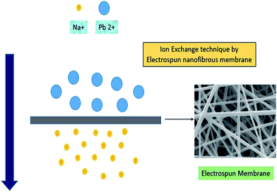 | ||
| Fig. 14 Ion-exchange technique by utilizing the electrospun fibrous membrane. [Note: plotted and modified by taking the figure from ref. 122]. | ||
6.4 Adsorption of pollutants
A major class of pollutants in the river system is heavy and toxic metals, which mainly come from industrial discharge. The large surface area of nanofibers enables more functional groups to be exposed to the contaminants for their removal. Where the base material does not contain an appropriate functional group, a functionalization method, such as blending and chemical treatment, can also be used. Thus, a wide range of functional molecules has been doped into electrospun nanofibers for pollutant adsorption.Polymethylmethacrylate (PMMA) loaded with rhodanine (Rhd) through a blending process was tested for removal of Ag(I) and Pb(II) ions through dead-end filtration methodology. In this study, the highest adsorptivity value was found to be 65.1% and 60.4% of the initial silver ion and lead ion concentration, respectively, for a duration of 10 s.123 After adsorption of the pollutants, the membrane can be recovered by washing in nitric acid solution. Table 13 shows the viability of electrospun membranes used for adsorption of organic pollutants and toxic metals.
| Material of the membrane | Chemical adsorption | Adsorption capacity | References |
|---|---|---|---|
| PVA/zeolite nanofibers | Cd2+ | 838.7 mg g−1 | 124 |
| PVA/zeolite nanofibers | Ni2+ | 342.8 mg g−1 | 124 |
| Rhodanine/PMMA | Ag+ | 125.7 mg m−2 | 123 |
| Rhodanine/PMMA | Pb2+ | 140.2 mg m−2 | 123 |
| Polyvinylidene fluoride (PVDF) blend (m-PEI/PVDF) | Methyl orange | 633.3 mg g−1 | 125 |
| Vinyl-modified mesoporous poly(acrylic acid)/SiO2 | Malachite green | 240.49 mg g−1 | 126 |
6.5 Other applications
There are a few other water treatment applications that can be effectively carried out by utilizing the electrospun membranes. These include microbial removal and heavy metal removal.| Microbes | PHA fibrous material (removal%) | PHA with sorbent (removal%) |
|---|---|---|
| B. subtilis | 81.9% | 87.9% |
| M. luteus | 63.7% | 61.1% |
| E. coli | 32.1% | 55.5% |
| S. cerevisiae | 74.2% | 75.5% |
It has even been shown that electrospun polyurethane nanofibers on polypropylene substrate are able to eradicate E. coli from waste water, indicating that the nanofibrous membrane provides a physical barrier to bacteria/microbes.
Recently, Senthamizhan et al.129 have shown that dithiothreitol-capped gold nanoclusters (AuNCs) are successfully incorporated into cavities in the form of pores in electrospun porous cellulose acetate fibers (pCAFs), and their assembly creates a “nanotrap” for effective adsorption of Pb2+ metal ions.129 Table 15 shows the removal efficiency% of different toxic metal ions while using the pCAFM/AuNC electrospun membrane.
| Toxic metal ions | Removal efficiency% |
|---|---|
| Lead (Pb) | 99.9 |
| Nickel (Ni) | 80.1 |
| Manganese (Mn) | 77.5 |
| Cadmium (Cd) | 91.2 |
| Zinc (Zn) | 95.8 |
| Mercury (Hg) | 56.5 |
In addition to this, currently, 1D nanostructures in the form of fibers, wires, rods, belts, and tubes have attracted plenty of attention due to their novel properties and diverse applications. Advanced techniques have been developed in order to fabricate 1D nanostructures with well-controlled morphology, quality, and chemical composition. Comparatively, 1D nanostructures and nanofibers exhibit a high specific surface area due to their small diameter and porosity. Thus, electrospinning was found to be a promising technique for producing ultrathin nanofibers. Recently, iron oxide–alumina nanocomposite fibers were prepared by an electrospinning technique for the removal of heavy metal ions from aqueous solution.130 Electrospun membranes are even highly efficient in separating a complex emulsion system of water, glycerol, biodiesel, un-reacted oil, soap, and catalyst, with the water, soap and pollutants forming agglomerates that are larger than the pore size of the membrane. Thus, the electrospun membrane is able to remove the agglomerates according to the size-exclusion principle.
7. Research challenges and limitations
In spite of so many advantages of electrospun nanofibrous membranes, there are some drawbacks that influence the membrane structure. The research challenges must be discussed so that these can be controlled in future by optimizing the parameters. The recent limitations of the electrospun nanofibrous membrane are as follows:• Other limitations include micro-cracking, corner rounding and temperature-induced problems.
• Fabrication of electrospun membranes on an industrial scale.
• Additionally, precise control of membrane uniformity, pore size distribution, and the barrier layer and support layer thicknesses must be achieved by the electrospinning technique on an industrial scale.
• Typically, the selection of suitable materials and proper incorporation routes to introduce the desired functionality, during or after electrospinning, is critical to generate a suitable nanofibrous membrane to meet specific needs.
• To provide the electrospinning technique with cost effective filtration and separation technology.
7.1 Future perspectives
Compared to the conventional technique for producing polymeric and composite membranes, electrospun nanofibrous membranes seem to be more effective due to their uniform pore size, interconnectivity of the pores and mechanical behaviour. Thus, there are some applications that can be further investigated to ensure the potential of the electrospinning technique:The electrospun nanofibrous membrane plays a key role in the field of water treatment, but more investigation can be done with respect to ultrafiltration and nanofiltration (reverse osmosis).
The practical use of electrospun nanofibrous membranes in reverse osmosis (RO) can be further studied.
To render the membrane distillation (MD) process effective, a high surface hydrophobicity membrane can be generated.
For the removal of hazardous and toxic components from water by adsorption, metal oxides or nanoparticles can be incorporated in the electrospun nanofibrous membrane.
Even partially hydrophilic membranes can be fabricated by using electrospinning techniques that can be further utilized in forward osmosis (FO) processes.
The general characteristics of the ideal membrane, such as uniform pore size, interconnectivity of the pores, tensile strength, and mechanical behaviour, must be improved by utilizing techniques such as post-thermal treatment and chemical treatment.
Durability and longevity should be one of the important areas of research and development while generating membranes by the electrospinning technique.
8. Conclusion
The research and development of electrospun nanofibrous membranes has gained a lot of attention from researchers because of its high versatility. The generation of non-woven nanofibrous membranes via the electrospinning technique has emerged as one of the crucial processes in membrane technology in the field of environmental application. The electrospinning technique is capable of producing membranes with high surface area, high surface area to volume ratio, uniform pore size, and high pore interconnectivity, which enhances the performance of the nanofibrous membrane. Additionally, in recent research, nanoparticles have been incorporated into the electrospun membranes to improve the performance. Furthermore, the electrospinning process is a reliable technique that may optimize the membrane structure. Electrospun membranes play a key role in the removal of small particles, by utilizing the membrane filtration (MF) process, and in desalination by membrane distillation (MD). Electrospun nanofibrous membranes can also be modified by considering the properties, such as pore size, hydrophobicity, tensile strength, and mechanical behaviour. In order to increase the permeation and water flux, properties such as pore size and thickness can be optimized. Despite all the advantages, there are some limitations, such as upgrading the technique to a large industrial scale for commercialization. Thus, special focus has been given to the high durability and stability of the electrospun membranes in order to overcome this issue. In the recent era, the electrospinning technique became one of the crucial processes that influenced the research and development on water treatment applications. Therefore, it can be concluded that the electrospinning technique is the most promising candidate for future membrane fabrication because electrospun nanofibrous membranes, as the next generation of filtration media, have promising features with respect to advanced filtration. In order to enhance the morphological and topographical features of electrospun nanofibers, various methodologies, including molecular bonding, in situ polymerization, and addition of molecular dopants, can be coupled with electrospinning technology. Moreover, strategies for surface modification, e.g. nanoparticle coating, treatment with chemicals or heat, grafting, and interfacial polymerization, are found to be suitable techniques to alter the surface characteristics and improve the filtration performance. Additionally, electrospun nanofibers were also effectively used in oily wastewater treatment. In recent years, many groups have paid more attention to the functionalities of electrospun nanofibers and have improved their application at an industrial scale.Acknowledgements
The authors would like to express gratitude for the financial support from the Ministry of Science and Technology, Republic of China (Taiwan) under grant number: 104-2221-E-027-004MY3 and also to the Institute of Environmental Engineering & Management (IEEM), National Taipei University of Technology, for supporting related research management activities.References
- S. Ramakrishna and M. M. A. Shirazi, Desalination, 2013, 308, 198–208 CrossRef.
- A. Kargari and M. M. A. Shirazi, in Encyclopedia of Energy Engineering and Technology, CRC Press, 2014, vol. 4 Search PubMed.
- F. Mushtaq, M. Guerrero, M. S. Sakar, M. Hoop, A. M. Lindo, J. Sort, X. Chen, B. J. Nelson, E. Pellicer and S. Pané, J. Mater. Chem. A, 2015, 3, 23670–23676 CAS.
- K. R. Reddy, K. Nakata, T. Ochiai, T. Murakami, D. A. Tryk and A. Fujishima, J. Nanosci. Nanotechnol., 2011, 11, 3692–3695 CrossRef CAS PubMed.
- K. R. Reddy, B. C. Sin, K. S. Ryu, J.-C. Kim, H. Chung and Y. Lee, Synth. Met., 2009, 159, 595–603 CrossRef CAS.
- K. R. Reddy, V. G. Gomes and M. Hassan, Mater. Res. Express, 2014, 1, 015012 CrossRef.
- K. R. Reddy, M. Hassan and V. G. Gomes, Appl. Catal., A, 2015, 489, 1–16 CrossRef CAS.
- K. R. Reddy, K. Nakata, T. Ochiai, T. Murakami, D. A. Tryk and A. Fujishima, J. Nanosci. Nanotechnol., 2010, 10, 7951–7957 CrossRef CAS PubMed.
- N. Bhardwaj and S. C. Kundu, Biotechnol. Adv., 2010, 28, 325–347 CrossRef CAS PubMed.
- O. Castaño, M. Eltohamy and H.-W. Kim, Nanotechnology in Regenerative Medicine: Methods and Protocols, 2012, 127–140 Search PubMed.
- F. Anton, US Pat., US1975504 A, 1934.
- S. Ramakrishna, K. Fujihara, W.-E. Teo, T. Yong, Z. Ma and R. Ramaseshan, Mater. Today, 2006, 9, 40–50 CrossRef CAS.
- R. Barhate and S. Ramakrishna, J. Membr. Sci., 2007, 296, 1–8 CrossRef CAS.
- T. Mokhena, V. Jacobs and A. Luyt, eXPRESS Polym. Lett., 2015, 9, 839–880 CrossRef CAS.
- K. R. Reddy, H. M. Jeong, Y. Lee and A. V. Raghu, J. Polym. Sci., Part A: Polym. Chem., 2010, 48, 1477–1484 CrossRef CAS.
- S. Subramanian and R. Seeram, Desalination, 2013, 308, 198–208 CrossRef CAS.
- M. Essalhi and M. Khayet, J. Membr. Sci., 2013, 433, 167–179 CrossRef CAS.
- S. S. Ray, S.-S. Chen, N. C. Nguyen, H. T. Nguyen, C.-W. Li, J. Wang and B. Yan, Chem. Eng. J., 2016, 304, 962–969 CrossRef CAS.
- N. C. Nguyen, H. T. Nguyen, S.-T. Ho, S.-S. Chen, H. H. Ngo, W. Guo, S. S. Ray and H.-T. Hsu, Sci. Total Environ., 2016, 557, 44–50 CrossRef PubMed.
- N. C. Nguyen, S.-S. Chen, H. T. Nguyen, S. S. Ray, H. H. Ngo, W. Guo and P.-H. Lin, Water Res., 2016, 91, 305–313 CrossRef CAS PubMed.
- C. Shao, H. Guan, Y. Liu, J. Gong, N. Yu and X. Yang, J. Cryst. Growth, 2004, 267, 380–384 CrossRef CAS.
- D. Aussawasathien, C. Teerawattananon and A. Vongachariya, J. Membr. Sci., 2008, 315, 11–19 CrossRef CAS.
- J. Deitzel, J. Kleinmeyer, J. Hirvonen and N. B. Tan, Polymer, 2001, 42, 8163–8170 CrossRef CAS.
- H. Fong and D. H. Reneker, Electrospinning and the formation of nanofibers, chapter, 2001 Search PubMed.
- G. Taylor, Proc. R. Soc. London, Ser. A, 1969 DOI:10.1098/rspa.1969.0205.
- A. Yousef, N. A. Barakat, T. Amna, A. R. Unnithan, S. S. Al-Deyab and H. Y. Kim, J. Lumin., 2012, 132, 1668–1677 CrossRef CAS.
- C. Feng, K. C. Khulbe, T. Matsuura, S. Tabe and A. F. Ismail, Sep. Purif. Technol., 2013, 102, 118–135 CrossRef CAS.
- P. K. Baumgarten, J. Colloid Interface Sci., 1971, 36, 71–79 CrossRef CAS.
- Z.-M. Huang, Y.-Z. Zhang, M. Kotaki and S. Ramakrishna, Compos. Sci. Technol., 2003, 63, 2223–2253 CrossRef CAS.
- M. M. A. Shirazi, D. Bastani, A. Kargari and M. Tabatabaei, Desalin. Water Treat., 2013, 51, 6003–6008 CrossRef CAS.
- A. Alkhudhiri, N. Darwish and N. Hilal, Desalination, 2012, 287, 2–18 CrossRef CAS.
- L. D. Tijing, J.-S. Choi, S. Lee, S.-H. Kim and H. K. Shon, J. Membr. Sci., 2014, 453, 435–462 CrossRef CAS.
- Y. Shin, M. Hohman, M. Brenner and G. Rutledge, Polymer, 2001, 42, 09955–09967 CrossRef CAS.
- S. Sundarrajan, R. Balamurugan, S. Kaur and S. Ramakrishna, Drying Technol., 2013, 31, 163–169 CrossRef CAS.
- S. Kaur, S. Sundarrajan, D. Rana, R. Sridhar, R. Gopal, T. Matsuura and S. Ramakrishna, J. Mater. Sci., 2014, 49, 6143–6159 CrossRef CAS.
- B. S. Lalia, V. Kochkodan, R. Hashaikeh and N. Hilal, Desalination, 2013, 326, 77–95 CrossRef CAS.
- J. Mulder, Basic principles of membrane technology, Springer Science & Business Media, 2012 Search PubMed.
- E. Drioli and L. Giorno, Membrane operations: innovative separations and transformations, Wiley-VCH, 2009 Search PubMed.
- J. Cadotte, R. Petersen, R. Larson and E. Erickson, Desalination, 1980, 32, 25–31 CrossRef.
- J. Cadotte, R. Forester, M. Kim, R. Petersen and T. Stocker, Desalination, 1988, 70, 77–88 CrossRef CAS.
- F. Sadeghi, Developing of microporous polypropylene by stretching, PhD Thesis, Ecole Polytechnique de Montreal, Canada, 2007.
- K. Trommer and B. Morgenstern, J. Appl. Polym. Sci., 2010, 115, 2119–2126 CrossRef CAS.
- C. R. Martin, M. Nishizawa, K. Jirage and M. Kang, J. Phys. Chem. B, 2001, 105, 1925–1934 CrossRef CAS.
- X. Wang, C. Drew, S.-H. Lee, K. J. Senecal, J. Kumar and L. A. Samuelson, Nano Lett., 2002, 2, 1273–1275 CrossRef CAS.
- M. M. Demir, I. Yilgor, E. Yilgor and B. Erman, Polymer, 2002, 43, 3303–3309 CrossRef CAS.
- A. Frenot and I. S. Chronakis, Curr. Opin. Colloid Interface Sci., 2003, 8, 64–75 CrossRef CAS.
- P. Gibson, H. Schreuder-Gibson and D. Rivin, Colloids Surf., A, 2001, 187, 469–481 CrossRef.
- N. Wang, Y. Zhao and L. Jiang, Macromol. Rapid Commun., 2008, 29, 485–489 CrossRef CAS.
- F. Cengiz, I. Krucińska, E. Gliścińska, M. Chrzanowski and F. Goektepe, Fibres Text. East. Eur., 2009, 17, 72 Search PubMed.
- D. Li, Y. Wang and Y. Xia, Adv. Mater., 2004, 16, 361–366 CrossRef CAS.
- Q. Peng, X.-Y. Sun, J. C. Spagnola, G. K. Hyde, R. J. Spontak and G. N. Parsons, Nano Lett., 2007, 7, 719–722 CrossRef CAS PubMed.
- H. S. Yoo, T. G. Kim and T. G. Park, Adv. Drug Delivery Rev., 2009, 61, 1033–1042 CrossRef CAS PubMed.
- E. Formo, E. Lee, D. Campbell and Y. Xia, Nano Lett., 2008, 8, 668–672 CrossRef CAS PubMed.
- B. Ding, H. Y. Kim, S. C. Lee, C. L. Shao, D. R. Lee, S. J. Park, G. B. Kwag and K. J. Choi, J. Polym. Sci., Part B: Polym. Phys., 2002, 40, 1261–1268 CrossRef CAS.
- P. Gibson, H. Schreuder-Gibson and C. Pentheny, J. Ind. Text., 1998, 28, 63–72 CrossRef CAS.
- J. Prince, G. Singh, D. Rana, T. Matsuura, V. Anbharasi and T. Shanmugasundaram, J. Membr. Sci., 2012, 397, 80–86 CrossRef.
- B. S. Lalia, E. Guillen-Burrieza, H. A. Arafat and R. Hashaikeh, J. Membr. Sci., 2013, 428, 104–115 CrossRef CAS.
- R. Gopal, S. Kaur, Z. Ma, C. Chan, S. Ramakrishna and T. Matsuura, J. Membr. Sci., 2006, 281, 581–586 CrossRef CAS.
- C. Feng, K. Khulbe, T. Matsuura, R. Gopal, S. Kaur, S. Ramakrishna and M. Khayet, J. Membr. Sci., 2008, 311, 1–6 CrossRef CAS.
- M. Khayet and T. Matsuura, Membrane Distillation: Principles and Applications, Elsevier, Amsterdam, 1st edn, 2011 Search PubMed.
- S. Kaur, D. Rana, T. Matsuura, S. Sundarrajan and S. Ramakrishna, J. Membr. Sci., 2012, 390, 235–242 CrossRef.
- Z. Zhao, J. Zheng, M. Wang, H. Zhang and C. C. Han, J. Membr. Sci., 2012, 394, 209–217 CrossRef.
- S. Sukigara, M. Gandhi, J. Ayutsede, M. Micklus and F. Ko, Polymer, 2003, 44, 5721–5727 CrossRef CAS.
- M. Yanilmaz, F. Kalaoglu, H. Karakas and A. S. Sarac, J. Appl. Polym. Sci., 2012, 125, 4100–4108 CrossRef CAS.
- J. Deitzel, J. Kleinmeyer, D. Harris and N. B. Tan, Polymer, 2001, 42, 261–272 CrossRef CAS.
- S. Tan, R. Inai, M. Kotaki and S. Ramakrishna, Polymer, 2005, 46, 6128–6134 CrossRef CAS.
- W. K. Son, J. H. Youk, T. S. Lee and W. H. Park, Polymer, 2004, 45, 2959–2966 CrossRef CAS.
- M. F. Hossain, R. H. Gong and M. Rigout, J. Text. Inst., 2016, 107, 1–11 CrossRef CAS.
- M. Nangrejo, F. Bragman, Z. Ahmad, E. Stride and M. Edirisinghe, Mater. Lett., 2012, 68, 482–485 CrossRef CAS.
- P. Heikkilä and A. Harlin, Eur. Polym. J., 2008, 44, 3067–3079 CrossRef.
- B. Ding, M. Wang, X. Wang, J. Yu and G. Sun, Mater. Today, 2010, 13, 16–27 CrossRef CAS.
- H. Fashandi and M. Karimi, Polymer, 2012, 53, 5832–5849 CrossRef CAS.
- Y. Dzenis and Y. Wen, MRS Proceedings, 2001 DOI:10.1557/PROC-702-U5.4.1.
- X. Zong, K. Kim, D. Fang, S. Ran, B. S. Hsiao and B. Chu, Polymer, 2002, 43, 4403–4412 CrossRef CAS.
- J. Deitzel, W. Kosik, S. McKnight, N. B. Tan, J. DeSimone and S. Crette, Polymer, 2002, 43, 1025–1029 CrossRef CAS.
- G.-d. Kang and Y.-m. Cao, J. Membr. Sci., 2014, 463, 145–165 CrossRef CAS.
- A. F. Ismail and T. Matsuura, Sustainable membrane technology for energy, water, and environment, John Wiley & Sons, 2012 Search PubMed.
- K. Popat, Nanotechnology in Tissue Engineering and Regenerative Medicine, CRC Press, 2010 Search PubMed.
- J. Xue, M. He, H. Liu, Y. Niu, A. Crawford, P. D. Coates, D. Chen, R. Shi and L. Zhang, Biomaterials, 2014, 35, 9395–9405 CrossRef CAS PubMed.
- S. L. Shenoy, W. D. Bates, H. L. Frisch and G. E. Wnek, Polymer, 2005, 46, 3372–3384 CrossRef CAS.
- C. Mit-uppatham, M. Nithitanakul and P. Supaphol, Macromol. Symp., 2004 DOI:10.1002/masy.200451227.
- H. Fong, I. Chun and D. Reneker, Polymer, 1999, 40, 4585–4592 CrossRef CAS.
- J. Zhang, H. Liu, H. Xu, J.-X. Ding, X.-L. Zhuang, X.-S. Chen, F. Chang, J.-Z. Xu and Z.-M. Li, RSC Adv., 2014, 4, 41696–41704 RSC.
- R. Wang, Y. Liu, B. Li, B. S. Hsiao and B. Chu, J. Membr. Sci., 2012, 392, 167–174 CrossRef.
- M. S. Khil, D. I. Cha, H. Y. Kim, I. S. Kim and N. Bhattarai, J. Biomed. Mater. Res., Part B, 2003, 67, 675–679 CrossRef PubMed.
- X. Wang, Y.-G. Kim, C. Drew, B.-C. Ku, J. Kumar and L. A. Samuelson, Nano Lett., 2004, 4, 331–334 CrossRef CAS.
- B. Ding, C. Li, Y. Miyauchi, O. Kuwaki and S. Shiratori, Nanotechnology, 2006, 17, 3685 CrossRef CAS.
- T. Ogawa, B. Ding, Y. Sone and S. Shiratori, Nanotechnology, 2007, 18, 165607 CrossRef.
- A. Jaworek, A. Krupa, M. Lackowski, A. Sobczyk, T. Czech, S. Ramakrishna, S. Sundarrajan and D. Pliszka, J. Electrost., 2009, 67, 435–438 CrossRef CAS.
- J.-F. Zhang, D.-Z. Yang, F. Xu, Z.-P. Zhang, R.-X. Yin and J. Nie, Macromolecules, 2009, 42, 5278–5284 CrossRef CAS.
- L. Ghasemi-Mobarakeh, M. P. Prabhakaran, M. Morshed, M. H. Nasr-Esfahani and S. Ramakrishna, Mater. Sci. Eng., C, 2010, 30, 1129–1136 CrossRef CAS.
- D. Breite, M. Went, A. Prager and A. Schulze, Polymers, 2015, 7, 2017–2030 CrossRef CAS.
- E. Curcio and E. Drioli, Sep. Purif. Rev., 2005, 34, 35–86 CrossRef CAS.
- M. M. A. Shirazi, A. Kargari and M. Tabatabaei, Chemical Engineering and Processing: Process Intensification, 2014, 76, 16–25 CrossRef CAS.
- V. Gurau, M. J. Bluemle, E. S. De Castro, Y.-M. Tsou, J. A. Mann and T. A. Zawodzinski, J. Power Sources, 2006, 160, 1156–1162 CrossRef CAS.
- W. Zhang and B. Hallström, Desalination, 1990, 79, 1–12 CrossRef CAS.
- G. Hurwitz, G. R. Guillen and E. M. Hoek, J. Membr. Sci., 2010, 349, 349–357 CrossRef CAS.
- A. Al-Amoudi, P. Williams, A. Al-Hobaib and R. W. Lovitt, Appl. Surf. Sci., 2008, 254, 3983–3992 CrossRef CAS.
- M. Khayet, J. Mengual and T. Matsuura, J. Membr. Sci., 2005, 252, 101–113 CrossRef CAS.
- C. Jönsson and A.-S. Jönsson, J. Membr. Sci., 1995, 108, 79–87 CrossRef.
- L. Defrance and M. Jaffrin, J. Membr. Sci., 1999, 152, 203–210 CrossRef CAS.
- M. Sarbolouki, Sep. Sci. Technol., 1982, 17, 381–386 CrossRef CAS.
- W. R. Bowen and J. S. Welfoot, Chem. Eng. Sci., 2002, 57, 1393–1407 CrossRef CAS.
- K. D. Hughes, Google Patents, 2007.
- V. Thavasi, G. Singh and S. Ramakrishna, Energy Environ. Sci., 2008, 1, 205–221 CAS.
- J. Phattaranawik, R. Jiraratananon and A. Fane, J. Membr. Sci., 2003, 215, 75–85 CrossRef CAS.
- W. Zhou, J. He, S. Cui and W. Gao, Open Mater. Sci. J., 2011, 5, 51–55 CrossRef CAS.
- R. Moradi, J. Karimi-Sabet, M. Shariaty-Niassar and M. A. Koochaki, Polymers, 2015, 7, 1444–1463 CrossRef CAS.
- S. A. A. N. Nasreen, S. Sundarrajan, S. A. S. Nizar, R. Balamurugan and S. Ramakrishna, Membranes, 2013, 3, 266–284 CrossRef PubMed.
- N. Daels, S. De Vrieze, I. Sampers, B. Decostere, P. Westbroek, A. Dumoulin, P. Dejans, K. De Clerck and S. Van Hulle, Desalination, 2011, 275, 285–290 CrossRef CAS.
- N. Daels, S. De Vrieze, B. Decostere, P. Dejans, A. Dumoulin, K. De Clerck, P. Westbroek and S. W. Van Hulle, Desalination, 2010, 257, 170–176 CrossRef CAS.
- X. Wang, X. Chen, K. Yoon, D. Fang, B. S. Hsiao and B. Chu, Environ. Sci. Technol., 2005, 39, 7684–7691 CrossRef CAS PubMed.
- X. Wang, D. Fang, K. Yoon, B. S. Hsiao and B. Chu, J. Membr. Sci., 2006, 278, 261–268 CrossRef CAS.
- Y.-J. Kim, C. H. Ahn and M. O. Choi, Eur. Polym. J., 2010, 46, 1957–1965 CrossRef CAS.
- C.-I. Su, J.-H. Shih, M.-S. Huang, C.-M. Wang, W.-C. Shih and Y.-s. Liu, Fibers Polym., 2012, 13, 698–702 CrossRef CAS.
- M. Essalhi and M. Khayet, J. Membr. Sci., 2014, 454, 133–143 CrossRef CAS.
- J. Prince, D. Rana, G. Singh, T. Matsuura, T. J. Kai and T. Shanmugasundaram, Chem. Eng. J., 2014, 242, 387–396 CrossRef CAS.
- K. Yoon, K. Kim, X. Wang, D. Fang, B. S. Hsiao and B. Chu, Polymer, 2006, 47, 2434–2441 CrossRef CAS.
- S. Lee, G. Park, G. Amy, S.-K. Hong, S.-H. Moon, D.-H. Lee and J. Cho, J. Membr. Sci., 2002, 201, 191–201 CrossRef CAS.
- K. Yoon, B. S. Hsiao and B. Chu, J. Mater. Chem., 2008, 18, 5326–5334 RSC.
- H. An, C. Shin and G. Chase, J. Membr. Sci., 2006, 283, 84–87 CrossRef CAS.
- D. N. Tran, A. M. Marti and K. J. Balkus, Fibers, 2014, 2, 308–317 CrossRef.
- C.-H. Lee, C.-L. Chiang and S.-J. Liu, Sep. Purif. Technol., 2013, 118, 737–743 CrossRef CAS.
- L. R. Rad, A. Momeni, B. F. Ghazani, M. Irani, M. Mahmoudi and B. Noghreh, Chem. Eng. J., 2014, 256, 119–127 CrossRef CAS.
- Y. Ma, B. Zhang, H. Ma, M. Yu, L. Li and J. Li, Sci. China Mater., 2016, 1, 38–50 CrossRef.
- R. Xu, M. Jia, Y. Zhang and F. Li, Microporous Mesoporous Mater., 2012, 149, 111–118 CrossRef CAS.
- Y. y. Duan, J. Jia, S. h. Wang, W. Yan, L. Jin and Z. y. Wang, J. Appl. Polym. Sci., 2007, 106, 1208–1214 CrossRef CAS.
- I. Marova, V. Kundrat, P. Benesova, P. Matouskova and S. Obruca, Nanotechnology (IEEE-NANO), 2015 IEEE 15th International Conference on, 2015 Search PubMed.
- A. Senthamizhan, B. Balusamy, A. Celebioglu and T. Uyar, J. Mater. Chem. A, 2016 10.1039/C5TA09166G.
- A. Mahapatra, B. Mishra and G. Hota, J. Hazard. Mater., 2013, 258, 116–123 CrossRef PubMed.
| This journal is © The Royal Society of Chemistry 2016 |


