
Synthesis of Sn(1−x)Fex@FeySn(1−y)Oz nanohybrids via a simple programmed microfluidic process
Jugang Ma†
a,
Junmei Wang†a,
Xiaodi Zhong†b,
Getian Li†a and
Yujun Song*a
aCenter for Modern Physics Technology, Department of Applied Physics, School of Mathematics and Physics, University of Science & Technology Beijing, Beijing 100083, China. E-mail: songyj@ustb.edu.cn
bSchool of Materials Science and Engineering, Beihang University, Beijing 100191, China
First published on 19th August 2016
Abstract
Core–shell Sn(1−x)Fex@FeySn(1−y)Oz nanohybrids are synthesized via a simple programmed microfluidic process. Characterization by high resolution transmission electron microscopy, energy dispersion X-ray spectroscopy and X-ray diffraction indicates that their sizes, shapes, compositions and crystal structures can be conveniently tuned by reaction temperatures. Different from the orientated growth to rod shaped Sn(1−x)Fex@FeySn(1−y)Oz nanorods (x ≪ 0.1, y < 0.5) with tin-rich crystalline cores and amorphous shells mixing with tiny Fe@FeOx nanoparticles at a low reaction temperature (e.g., 30 °C), the Sn(1−x)Fex@FeySn(1−y)Oz nanospheres (x < 0.5, 0.5 < y < 1) with crystalline tin-rich FeSn alloy cores and surface oxidized tin ferrite shells can be formed at an elevated reaction temperature (e.g., 90 °C). A blue-shift was found in the photoluminescence spectrum due to the existence of Fe in Sn(1−x)Fex@FeySn(1−y)Oz nanospheres compared with those Sn@SnO2 nanohybrids. The superparamagnetic property observed in the nanospheres can be attributed to the SnFe alloy cores and amorphous tin ferrite shells. As to the portion of Fe doping of Sn@SnO2 nanorods mixed with Fe@FeOx nanoparticles formed at 30 °C, they exhibit paramagnetic properties with increased saturated magnetic fields.
1. Introduction
Hybrid nanomaterials (nanohybrids) with multi-functionalities have been intensively studied due to their potential application in many technological fields.1–6 Among them, the metal–metal oxide nanohybrids can be used in the next generation of optoelectronics, highly efficient catalysts, ultra-sensitive sensing systems and toxicological research.7–9 Sn nanoparticles grown on graphene by adding tin powder to the reaction of graphite oxide during thermal reduction both have a high energy and power density for supercapacitors.10 Nanocrystalline FeSn2 alloys, as negative electrodes, exhibit a much better electrochemical behavior and electrode stability.11 Pure or modified SnO2 nanocrystals have been used as ultra-sensitive gas sensors,12,13 solar cells, light emitting diodes, transparent electromagnetic shielding materials, etc.14 SnO2 also offers a high theoretical lithium storage capacity to improve the battery storage capability and durability.15,16By tuning the thermodynamic (reduction potential, activation energy, electronegativity, compatibility) and kinetic (temperature, time, concentration, solvent, diffusion coefficient) parameters, many new processes have been developed for the large-scale synthesis of varieties of nanohybrids, such as magneto-plasmonics, plasmonic-dielectrics, plasmonic-semiconductors, magneto-semiconductors, magneto-dielectrics, antiferromagnetism–ferromagnetism.17–26 Hybrid Co@CdSe nanoparticles have been synthesized by a multi-step reactive deposition epitaxial growth process invented by Klimov et al.27 Kumar et al. have developed multi-step seed synthesis and displacement methods to prepare Co@Au, Au@TiO2 and porous Cu@MnO2 nanoparticles.28,29 Fe@Au and Fe@Ag nanoparticles can be synthesized via a multi-step feeding salt reduction reaction in one pot.30,31 Halas et al. prepared Au@FexO nanohybrids by directly coating the second component on the preformed nanocluster.32 Based on the shell formation mechanism, these methods can be classified as the epitaxial growth, the displacement process and the direct deposition process. Among them, it is difficult for the epitaxial growth and displacement process to address the lattice mismatch among components and the interfacial stress caused by the large curvature at the nanoscale.6 Even though the direct deposition process can easily control the shell thickness, it is not easy to achieve a uniform growth of shells.32 For the preparation of some more complex nanoparticles (e.g., metal–semiconductor, Au–ZnO), both a solvothermal method and a hydrothermal method have to be used together or a complicated sol–gel phase transition process and in situ reduction have to be used simultaneously.18 Therefore, it is crucial to develop new methods for interface controlled nanohybrid synthesis.6,17,18
Lots of work has been done to resolve these issues. Beer et al. developed anion coordination and reduction methods for the shell thickness controlled synthesis of core–shell bimetallic nanoparticles (e.g., Pd@Au).33 Ouyang and Zhang developed a nonepitaxial growth method based on the ion substitution growth mechanism for addressing the large lattice mismatches in core–shell nanoparticles, and have prepared Au@CdSe nanohybrids successfully.6 Wang and Zhang further expanded their solvothermal method to the interface control of nanohybrids.17 Hou and Sun also developed a multi-step liquid precipitation-reduction to successfully prepare Fe3O4@Au@Ag multi-layered nanohybrids.34 Tian and Wang developed an atom-layer deposition and coating process to obtain ultra-thin layers (e.g., 2 nm thick Al2O3) on Au nanoclusters.26 Recently, Peng et al. invented a modified epitaxial growth method to successfully synthesize flower-like Au–Ni–ZnO nanohybrids and regulated their hybrid structures and properties.35 While Zheng and Fu et al. developed a high-temperature reduction–oxidization process to fabricate Pt–FeNi(OH)x nanohybrids with intertwined structures.36
Using the above methods, part of the above issues can be alleviated. Through in-depth analysis of key steps in the above methods, we found that regulation of the kinetic parameters in each stage of the nanoparticle formation is one of the keys to optimize their morphology and interfacial structure, which is also a required step to realize their industrial application. Usually, it is not easy for conventional batch-bottle methods to control the spatiotemporal kinetic parameters of each stage in the formation of nanohybrids during controlled scaling up. Thereby, the large-scale morphological and interfacial structure controlled synthesis of nanohybrids is still facing great challenges.
Among the different synthesis methods, microfluidic processes (MPs) have attracted great attention due to their precise spatial and temporal reaction control, and efficient mass and heat transfer, endowing the microstructure controlled synthesis of nanomaterials.4,21,37,38 Specifically, MPs have achieved success in control of the sizes, shapes, compositions and crystal phases of nanohybrids, which greatly affect their physicochemical properties.21,37,39,40 In this article, a simple programmed microfluidic process (SPMP) with stage-controlled reaction temperatures is utilized for the synthesis of Sn(1−x)Fex@FeySn(1−y)Oz nanohybrids of different sizes, shapes and compositions, which can be controlled simply by reaction temperatures. Sequenced reduction and co-precipitation reactions result in a core–shell structure where Fe is well-dispersed in Sn-rich metallic cores and Sn3O4 in Fe2O3 oxide shells at high temperature. And a superparamagnetic property of Sn(1−x)Fex@FeySn(1−y)Oz nanospheres can be observed just above 2 K (the lowest temperature during the measurement), indicating SnFe alloy cores surrounded by an amorphous layer of Sn3O4 doping Fe2O3 shells (or tin ferrite shells). They also show photoluminescence, unique from non-doping Sn@SnO2 nanohybrids.
2. Experimental section
2.1. Materials
SnCl2·2H2O (≥99.7%), FeCl2·4H2O (≥99.7%), NaBH4 (≥99.7%), polyvinylpyrrolidone (PVP, ≥99.7%, Mw = 10![[thin space (1/6-em)]](https://www.rsc.org/images/entities/char_2009.gif) 000), N-methyl-2-pyrrolidone (NMP, ≥99.7%) were used as purchased. Millipore ultrapure water with a resistivity of 18.2 MΩ cm was used throughout the experiments.
000), N-methyl-2-pyrrolidone (NMP, ≥99.7%) were used as purchased. Millipore ultrapure water with a resistivity of 18.2 MΩ cm was used throughout the experiments.
2.2. Synthesis of Sn(1−x)Fex@FeySn(1−y)Oz nanohybrids
For the setup of the simple programmed microfluidic process refer to our previous publication.41 The typical synthesis procedure is as follows. SnCl2·2H2O (0.14 mmol), FeCl2·4H2O (0.12 mmol) and PVP (0.088 g) were dissolved in 20 ml NMP. The reducing agent was prepared by dissolving 0.032 g NaBH4 in 20 ml NMP under N2 flow. The reaction temperature was controlled at 30 °C or 90 °C and the product was collected in a 3-necked glass bottle under N2 flow protection at the ambient temperature. After the synthesis was completed, nanohybrids were precipitated using a centrifuge at 15000 rpm for 30 min. The slurry was re-dispersed into the same volume of NMP and the centrifugation and re-dispersion processes were repeated twice. The final black slurry in the bottle was dried under vacuum and kept in desiccators for future use.
2.3. Characterization
The size, shape and morphologies of the nanohybrids were characterized by high resolution transmission electron microscopy (HR-TEM; JOEL 2100F, 200 kV). Chemical compositions at the center and edge locations of the nanohybrids were examined by energy dispersive X-ray spectroscopy (EDS) coupled to the HR-TEM. Powder X-ray diffraction (XRD) data of samples were collected on a D/max 2200 PC diffractometer (Cu Kα radiation, λ = 1.54056 Å, Rigaku, Japan). The photoluminescence (PL) was characterized by an FLS980 Edinburgh instrument which contains a xenon lamp and the excitation wavelength was set as 300 nm (room temperature). Their magnetic properties were evaluated by a room temperature hysteresis loop (RMHL) and thermal-magnetism (ZFC: zero-field cooling; FC: field cooling) curves measured by MPPS (SQUID, Quantum design) using an applied magnetic field of 100 Oe.3. Results and discussions
Facile control over the sizes, shapes and crystal structures of the nanohybrids can be achieved by SPMP.22,40 One of the most important kinetic parameters in nanohybrid formation is the synthesis temperature, which controls the reaction rate and determines the nucleation and growth process of nanoparticles.42,43 Here, nanohybrids synthesized at different temperatures show significant differences in sizes, shapes and compositions. As shown in Fig. 1a and d, nanohybrids synthesized at 30 °C give rod shapes, while nanohybrids of spherical shape can be obtained at 90 °C. The diameter and length of the nanorods (Fig. 1c) are 24.7 ± 5.6 nm and 57.8 ± 10.5 nm and the size of the nanospheres (Fig. 1f) is 15.9 ± 7.6 nm calculated from more than one hundred randomly selected nanohybrids. The high resolution TEM (HRTEM) images (Fig. 1b and e) clearly reveal a core–shell structure in both kinds of nanohybrids. The lattice spacing of the rod-shaped core is 0.278 nm, corresponding to the (101) plane of tetragonal tin (0.279 nm, PDF no. 04-0673). The lattice spacing of 0.355 nm in the core of the nanosphere (Fig. 1e) can be assigned as the (111) plane of α-tin (PDF no. 86-2266), less than the standard grey tin (0.375 nm) possibly due to the heavy alloying of Fe in nanoparticles at high reaction temperature.44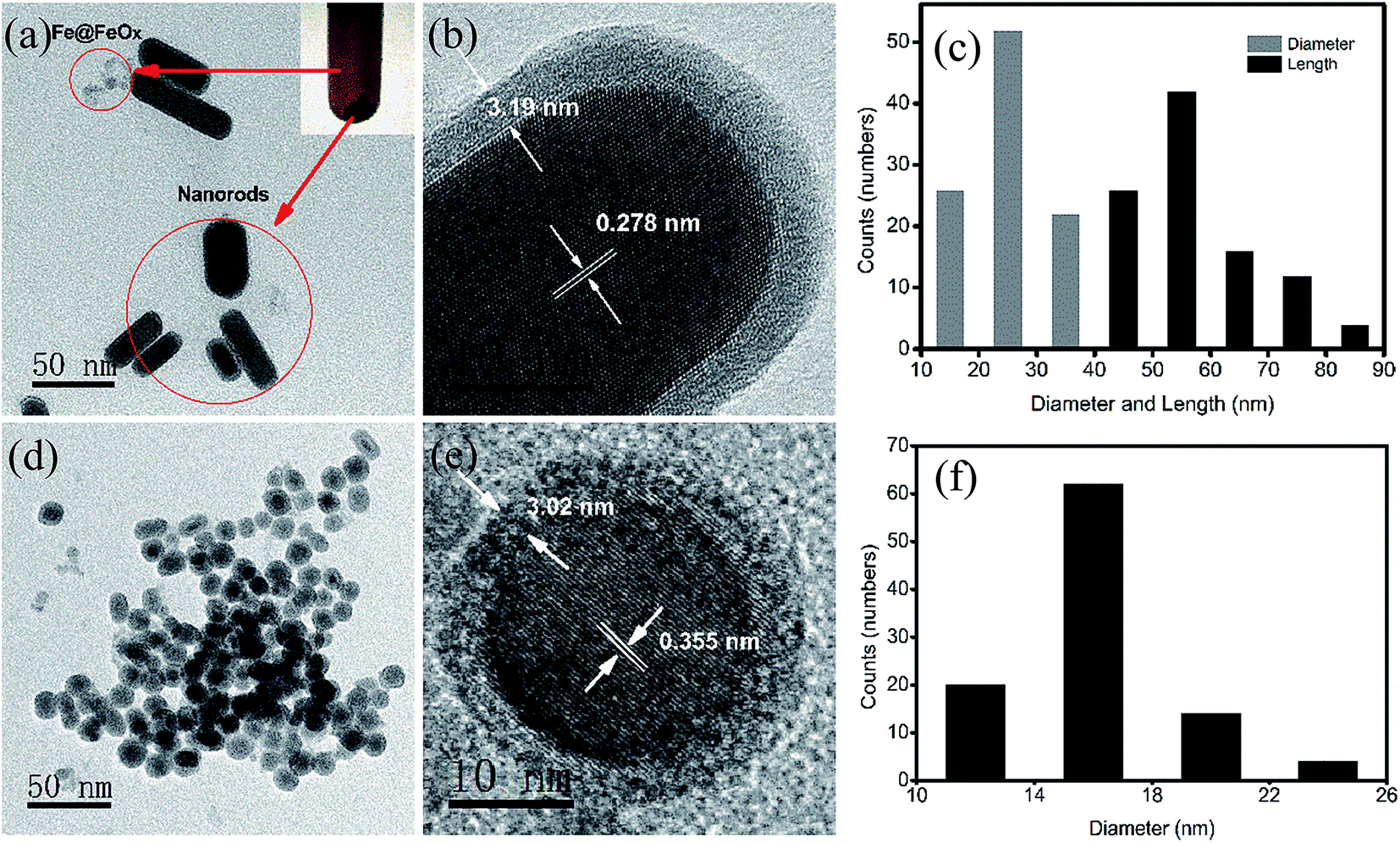 | ||
| Fig. 1 Wide view TEM image (a), HR-TEM image (b) and distribution histograms of the diameter and length (c) of Sn(1−x)Fex@FeySn(1−y)Oz core–shell nanorods synthesized at 30 °C. Wide view TEM image (d), HR-TEM image (e) and distribution histogram of diameter (f) of Sn(1−x)Fex@FeySn(1−y)Oz core–shell nanospheres synthesized at 90 °C. | ||
The amorphous phase of the shell in both kinds of nanohybrids can be clearly identified by the absence of lattice fringes. Clearly, the shell thickness decreases at high reaction temperatures, suggesting that the reducing reaction can be relatively enhanced compared with the redox and precipitation reactions. It is also interesting that the orientated growth direction ((101) plane) of the nanorods is quite similar to that of the Sn@SnO2 nanorods in our previous work.21
The compositions of the nanohybrids were further characterized by EDS and XRD. The scanning transmission electron microscope (STEM) images and the EDS spectra of the relative Fe and Sn distributions in the center and edge of the nanohybrids are illustrated in Fig. 2, further confirming the core shell structure and the related composition. The EDS of the nanorod shows that the core is mainly composed of Sn and the shell is composed of Sn, O and trace Fe (Fig. 2b and c). For the nanosphere, the core is mainly made of Sn and a distinct amount of Fe, as shown by the strong Sn peaks and the discernable Fe peaks (Fig. 2e and f). In the shell, the Fe signal is significantly higher than that in the core. But Sn still mainly serves as the main element (due to the metallic Sn cores and the probe resolution), suggesting that the oxide shell is very thin, as observed by the HR-TEM image (Fig. 1e). The XRD spectrum of nanorods in Fig. 3a suggests that all the main peaks at 30.6°, 32.8°, 43.8°, 44.9°, 55.3°, 62.5°, 63.7°, 64.5°, 72.4°, 73.1° and 79.4° can be indexed as the (200), (101), (220), (211), (301), (112), (400), (321), (420), (411) and (312) planes of tetragonal tin according to the standard tin sample (PDF no. 04-0673), and the weak peaks at 26.9° and 83.9° correspond to the (112) and (319) planes of SnO2 (PDF no. 78-1063). The XRD pattern of nanospheres (in Fig. 3b) has the strongest peak appearing at 24.7° and the other two peaks at 29.8° and 32.7°, which can be assigned to Fe2O3 (PDF no. 21-0920). Weak peaks at 18.3°, 31.6° and 32.9° correspond to the (100), (021) and (003) planes of Sn3O4 (PDF no. 20-1293). Peaks at 23.7°, 39.2°, 46.3° and 62.3° correspond to the (111), (220), (311) and (331) planes of α-tin (PDF no. 86-2266). Peaks at 30.6°, 32.0°, 44.9° and 62.5° of the XRD pattern correspond to the (200), (101), (211) and (112) planes of β-Sn (PDF no. 04-0673). While peaks at 41.4°, 45.8° and 58.5° can be assigned as the (002), (102) and (300) planes of Fe3Sn. Peaks of the pure crystalline iron phase cannot be identified in the nanospheres, further confirming the formation of FeSn alloys.
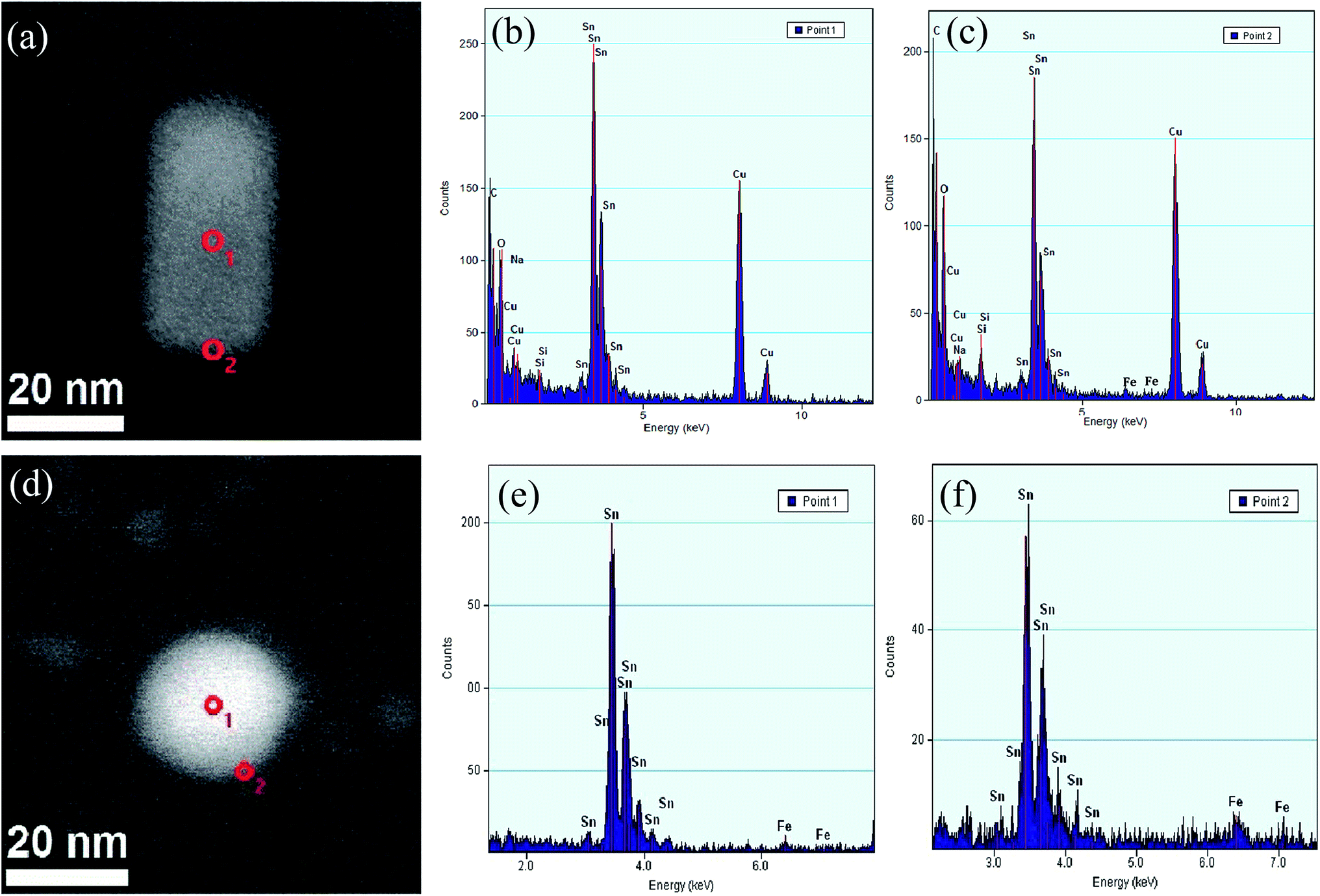 | ||
| Fig. 2 Bright-field image of one typical nanorod (a) and its EDS spectra in point 1 ((b) center area) and point 2 ((c) shell area). Bright-field image of one typical nanosphere (d) and its EDS spectrums in point 1 ((e) center area) and point 2 ((f) shell area). | ||
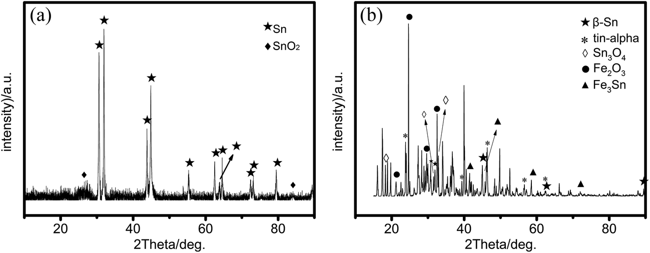 | ||
| Fig. 3 XRD patterns of Sn(1−x)Fex@FeySn(1−y)Oz nanorods (a) and the Sn(1−x)Fex@FeySn(1−y)Oz nanospheres (b). | ||
All of the above characterizations can help us depict the growth process of Sn(1−x)Fex@FeySn(1−y)Oz nanohybrids. In the competition of ion reduction, Sn2+ ions are preferentially reduced to Sn0 due to the relatively higher electrode potential (−0.13 V vs. SHE) compared with Fe2+ (−0.44 V vs. SHE).45 At a low temperature, the slow overall rate of reaction results in the preferred reduction of Sn2+ ions than of Fe2+ ions. The nucleation and growth of Sn atoms preferred rod shapes, and then the concentration of the reducing agent decreased before Fe2+ ions were reduced to Fe@FeOx. Since the Fe@FeOx nanoparticles were too small to be precipitated centrifugally (Fig. 1a), the XRD pattern in Fig. 3a does not show their peaks. At high temperature, Sn nuclei can be formed during this process more rapidly than Fe nuclei. Consequently, the growth of Sn nanocrystals consumed more Sn2+ ions, leading to a reduced Sn2+ ion concentration and relatively higher Fe2+ ion concentration that will gradually reduce more rapidly than tin ions. Thus, more Fe atoms will be included into the Sn nanoparticles to form an FeSn alloy, with the Fe content gradually increasing from the inner part to the outer part of the nanoparticles (reaction (1)). This is confirmed by our characterization that cores of the nanohybrids are mainly composed of Sn and the Fe concentration is much higher in the shells than in the cores. At the same time, the precipitation reactions to form metal hydroxides occur simultaneously with the reduction reaction because of the existence of dissolved oxygen and lots of H2O (the crystallization water from the Fe salt and some absorbed water in SnCl2 during the preparation of the reactant solution) and the alkalinity in the reaction solution increases as the NaBH4 is consumed, as shown in reactions (2) and (3) below. These metal hydroxides can deposit on the pre-formed metallic cores to form metal hydroxide shells that can change to metal oxides after drying to powder. In addition, some surface atoms of the pre-formed metallic cores can be re-oxidized again to form surface metal oxides to increase the shell thickness (reaction (4)). Some metal ions (e.g., Sn2+, Fe2+) in the solution can be oxidized to higher valence (e.g., Sn4+, Fe3+) as the reducing agent is consumed; these can be included in the surface oxides to form the complex shell as confirmed by EDS, XRD and HR-TEM measurements. The formation of the processes of gradient core–shell nanostructures by a coupled competitive reducing–precipitation reaction at different temperatures was shown in scheme 1.
| Fe2+ (trace) + Sn2+ + BH4− + H2O → [Sn(1−x)Fex]colloid·PVP + BO2− + H2 | (1) |
| Sn2+ + 2BH4− + 2H2O → Sn(OH)2 + 2BH3 + 2H2 | (2) |
| Fe2+ + 2BH4− + 2H2O → Fe(OH)2 + 2BH3 + 2H2 | (3) |
| [Sn(1−x)Fex]colloid·PVP + Sn(OH)2 + Fe(OH)2 → [Sn(1−x)Fex]@[FeySn(1−y)Oz]·PVP + H2O | (4) |
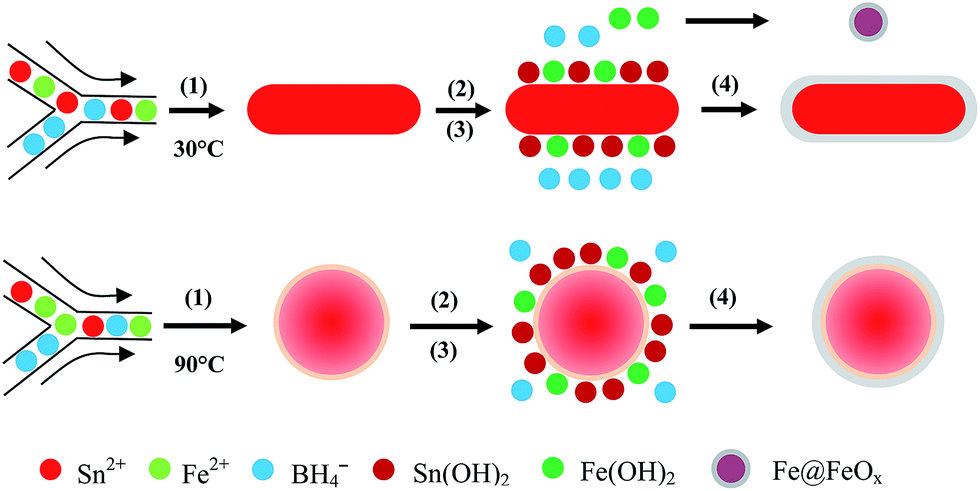 | ||
| Scheme 1 Cartooned formation of the processes of core–shell nanostructures by a coupled competitive reducing–precipitation reaction at different temperatures. | ||
The crystal structures and shapes of tin-based nanohybrids were thermodynamically controlled during their growth. The nanorods with a tetragonal phase synthesized at low temperature can be formed based on the orientated growth of the tin core along the plane with a high surface energy (e.g., (101) plane), satisfying the need to minimize the total system energy.46 While at elevated temperature, a large amount of Sn nuclei can be formed in the Y-shaped micro-connector and rapidly grow to grey tin, and the orientated growth along the high energy surface plane is not favorable. While the relative low energy surface (111) plane can be formed at high temperatures, as confirmed by the high probability (101) plane in the nanorods with tetragonal tin cores and the (111) plane in the spherical nanohybrids.22 Consequently, nanospheres are formed.
Both kinds of nanohybrid present special room temperature photoluminescence properties (Fig. 4). The emission spectrum of nanorods exhibits one main peak and four little peaks, as shown in Fig. 4a. The peak at 345 nm reveals a strong ultra-violet (UV) emission, and can be attributed to the direct bandgap of SnO2, suggesting that the dipole-forbidden rule (the band-edge radiative transition) was overcome in the Sn@SnO2 nanorods, which shows a slight blue shift compared with Sn@SnO2 due to the slight doping of Fe in SnO2. The other four peaks or shoulders can be ascribed to the effects of oxygen vacancies, tin interstitials or dangling,47 which are different from those in the non-doping Sn@SnO2 nanorods.21 In Fig. 4b, the emission of nanospheres is centered at 417 nm (2.98 eV), showing a significant blue shift (58 nm) compared to the nanohybrids in our previous work,21 mainly due to the combined effect of size reduction and compressive stress caused by the heavy Fe doping.48
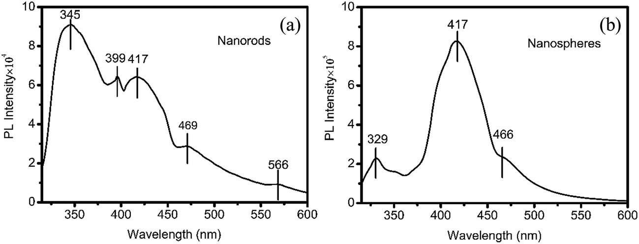 | ||
| Fig. 4 Photoluminescence spectra of Sn(1−x)Fex@FeySn(1−y)Oz nanorods (a) and Sn(1−x)Fex@FeySn(1−y)Oz nanospheres (b). | ||
The paramagnetic and superparamagnetic nature of the synthesized nanohybrids are revealed in Fig. 5. Their magnetic parameters are summarized in Table 1. The low coercivity in Fig. 5a and the ZFC and FC curves in Fig. 5c confirm the paramagnetic nature of the nanorods. The ZFC and FC curves in Fig. 5d suggest the superparamagnetic nature of the nanospheres. The non-zero coercivity in Fig. 5a (black line) can be attributed to the enhanced magnetic surface anisotropy and the dipole interaction among nanoparticles. The emerging temperature of ZFC and FC curves suggests that its Tb is less than the starting temperature (2 K). According to the simple expression on the Tb for magnetic NPs without interaction, Tb should be proportional to their volumes.43,49,50 This low Tb value can be ascribed to the tiny Sn1−xFex cores surrounded by the amorphous tin ferrites (mixture of tin oxides and iron oxides). In the hysteresis loop, a much reduced value of Ms compared with Fe nanoparticles synthesized via the same method can be observed, which indicates the lower content of iron in the particles compared with Fe nanoparticles in our previous work.50 The poor crystallinity of oxide shells can also contribute to their reduced Ms.
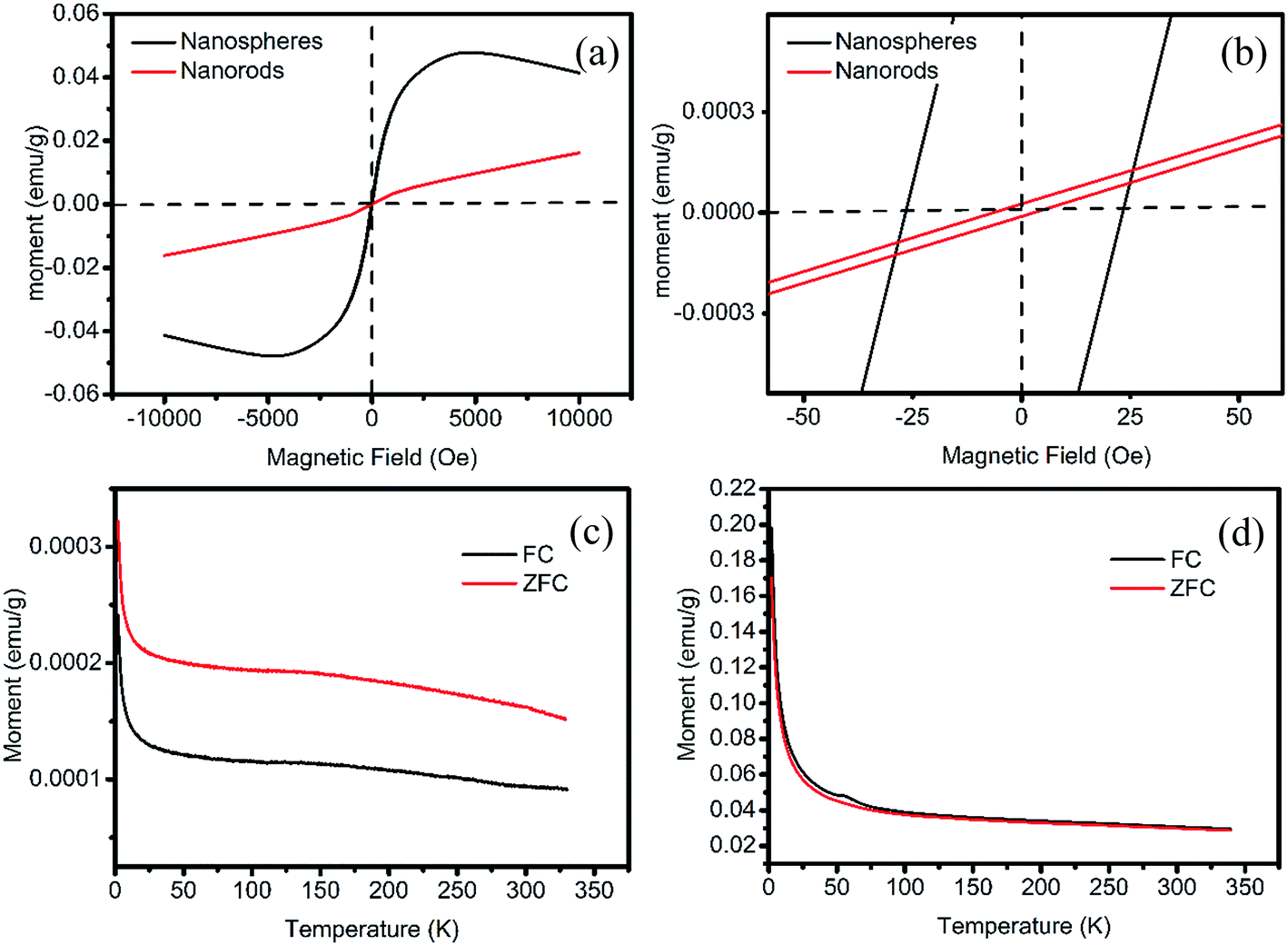 | ||
| Fig. 5 The full range (a) and the magnified central part (b) of room temperature hysteresis loops of the Sn(1−x)Fex@FeySn(1−y)Oz nanohybrids and the thermal-magnetism curves (ZFC: zero-field cooling; FC: field cooling) of nanorods (c) and nanospheres (d). | ||
| Sample | Hc, Oe | M0, emu g−1 | ||
|---|---|---|---|---|
| Left | Right | M0,t | M0,b | |
| Nanorods | −4.1 | 5.6 | 2.2 × 10⁻⁵ | −9.3 × 10⁻⁵ |
| Nanospheres | −26.6 | 23.2 | 1.2 × 10⁻³ | −1.0 × 10⁻³ |
4. Conclusion
Sn(1−x)Fex@FeySn(1−y)Oz nanohybrids of different shapes (nanorods or nanospheres) and oriented crystal planes have been successfully synthesized via a simple programmed microfluidic process (SPMP) by simply tuning the reaction temperatures. Unique optical and magnetic properties were observed due to the Fe-doping. A blue-shift of about 58 nm can be achieved in hybrid nanospheres doped with Fe and/or iron oxides compared with that of pure Sn@SnO2. Superparamagnetic property can also be realized in the nanohybrids synthesized at high temperature with a Tb just above the starting measured temperature (2 K).Acknowledgements
This work was supported by NSFC (Grant no. 51371018 & 50971010), the Fundamental Research Funds for the Central Universities (FRF-BR-15-027A & FRF-BR-14-001B).References
- P. D. Cozzoli, T. Pellegrino and L. Manna, Chem. Soc. Rev., 2006, 35, 1195–1208 RSC
.
- Y. Song, Y. Wang, B. Li, C. Fernandes and H. E. Ruda, Nanoscale, 2013, 5, 6779–6789 RSC
- J. A. Farmer and C. T. Campbell, Science, 2010, 329, 933–936 CrossRef CAS PubMed
- A. J. Demello, Nature, 2006, 442, 394 CrossRef CAS PubMed
- K. J. Carroll, D. M. Hudgins, S. R. Spurgeon, K. M. Kemner, B. Mishra, M. I. Boyanov, L. W. Brown, M. L. Taheri and E. E. Carpenter, One-Pot Aqueous Synthesis of Fe and Ag Core/Shell Nanoparticles, 2010 Search PubMed
- J. Zhang, Y. Tang, K. Lee and M. Ouyang, Science, 2010, 327, 1634–1638 CrossRef CAS PubMed
- J. Junyi, Z. Guanghui, C. Hongyu, L. Yang, Z. Guoliang, Z. Fengbao and F. Xiaobin, J. Mater. Chem., 2011, 21, 14498–14501 RSC
- Y. Cheng, Y. Fan, Y. Pei and M. Qiao, Catal. Sci. Technol., 2015, 5, 3903–3916 CAS
- N. B. Saleh, A. Afrooz, J. H. Bisesi, N. Aich, J. Plazas-Tuttle and T. Sabo-Attwood, Nanomaterials, 2014, 4, 372–407 CrossRef
- Z. Qin, Z. J. Li, M. Zhang, B. C. Yang and R. A. Outlaw, J. Power Sources, 2012, 217, 303–308 CrossRef CAS
- U. G. Nwokeke, R. Alcantara, J. L. Tirado, R. Stoyanova and E. Zhecheva, J. Power Sources, 2011, 196, 6768–6771 CrossRef CAS
- M. Epifani, J. Arbiol, E. Pellicer, E. Comini, P. Siciliano, G. Faglia and J. R. Morante, Cryst. Growth Des., 2008, 8, 1774–1778 CAS
- Z. Li, Q. Zhao, W. Fan and J. Zhan, Nanoscale, 2011, 3, 1646–1652 RSC
- H. Hartnagel, A. L. Dawar, A. K. Jain and C. Jagadish, Semiconducting transparent thin films, Institute of Physics Pub, 1995 Search PubMed
- H. B. Wu, J. S. Chen, H. H. Hng and X. W. Lou, Nanoscale, 2012, 4, 2526–2542 RSC
- L. Chen, P. Wu, H. Wang, Y. Ye, B. Xu, G. Cao, Y. Zhou, T. Lu and Y. Yang, J. Power Sources, 2014, 247, 178–183 CrossRef CAS
- Z. Zhang, B. Xu and X. Wang, Chem. Soc. Rev., 2014, 43, 7870–7886 RSC
- R. Jiang, B. Li, C. Fang and J. Wang, Adv. Mater., 2014, 26, 5274–5309 CrossRef CAS PubMed
- Y. Song, J. Ding and Y. Wang, J. Phys. Chem. C, 2012, 116, 11343–11350 CAS
- R. Wang, W. Yang, Y. Song, X. Shen, J. Wang, X. Zhong, S. Li and Y. Song, Sci. Rep., 2015, 5, 9189 CrossRef PubMed
- S. Li, X. Zhong, Y. Song, X. Shen, J. Sun, Y. Song, R. Wang, M. Zhu, H. Zhong and A. Zheng, Controlled hybridization of Sn–SnO2 nanoparticles via simple-programmed microfluidic processes for tunable ultraviolet and blue emissions, 2014 Search PubMed
- Y. Song, S. Ji, Y.-J. Song, R. Li, J. Ding, X. Shen, R. Wang, R. Xu and X. Gu, J. Phys. Chem. C, 2013, 117, 17274–17284 CAS
- Y. Song, W. Yin, Y.-H. Wang, J.-P. Zhang, Y. Wang, R. Wang, J. Han, W. Wang, S. V. Nair and H. E. Ruda, Sci. Rep., 2014, 4 DOI:10.1038/srep04991
- J. Liu, W. Liu, Q. Sun, S. Wang, K. Sun, J. W. Schwank and R. Wang, Chem. Commun., 2014, 50, 1804–1807 RSC
- S. L. Zhang, Y. Liu, L. J. Collins-Mclntyre, T. Hesjedal, J. Y. Zhang, S. G. Wang and G. H. Yu, Sci. Rep., 2013, 3 DOI:10.1038/srep02087
- J. F. Li, Y. F. Huang, Y. Ding, Z. L. Yang, S. B. Li, X. S. Zhou, F. R. Fan, W. Zhang, Z. Y. Zhou, D. Y. Wu, Z. L. Wang and Z. Q. Tian, Nature, 2010, 464, 392 CrossRef CAS PubMed
- H. Kim, M. Achermann, L. Balet, J. A. Hollingsworth and V. I. Klimov, J. Am. Chem. Soc., 2005, 127, 544–546 CrossRef CAS PubMed
- N. Subramanian, J. Moreno, J. J. Spivey and C. S. S. R. Kumar, J. Phys. Chem. C, 2011, 115 DOI:10.1021/jp202215k
- F. Mohammad, J. Phys. Chem. Lett., 2010, 1 DOI:10.1021/jz101202a
- K. J. Carroll, D. M. Hudgins, S. Spurgeon, K. M. Kemner, B. Mishra, L. W. Brown and E. E. Carpenter, Chem. Mater., 2010, 22, 6291–6296 CrossRef CAS
- S. Cho, J. C. Idrobo, J. Olamit, K. Liu, N. D. Browning and S. M. Kauzlarich, Chem. Mater., 2005, 17, 3181–3186 CrossRef CAS
- C. S. Levin, C. Hofmann, T. A. Ali, A. T. Kelly, E. Morosan, P. Nordlander, K. H. Whitmire and N. J. Halas, ACS Nano, 2009, 3, 1379–1388 CrossRef CAS PubMed
- C. J. Serpell, J. Cookson, D. Ozkaya and P. D. Beer, Nat. Chem., 2011, 3, 478 CAS
- Z. Xu, Y. Hou and S. Sun, J. Am. Chem. Soc., 2007, 129, 8698 CrossRef CAS PubMed
- Y. Chen, D. Zeng, M. B. Cortie, A. Dowd, H. Guo, J. Wang and D. Peng, Small, 2015, 11, 1460–1469 CrossRef CAS PubMed
- G. Chen, Y. Zhao, G. Fu, P. N. Duchesne, L. Gu, Y. Zheng, X. Weng, M. Chen, P. Zhang, C. W. Pao, J. F. Lee and N. Zheng, Science, 2014, 344, 495–499 CrossRef CAS PubMed
- R. Wang, W. Yang, Y. Song, X. Shen, J. Wang, X. Zhong, S. Li and Y. Song, Sci. Rep., 2015, 5, 9189 CrossRef PubMed
- Y. Song, Y. Wang, S. Ji and J. Ding, Nano-Micro Lett., 2012, 4, 235–242 CrossRef CAS
- Y. Song and L. L. Henry, Nanoscale Res. Lett., 2009, 4, 1130 CrossRef CAS PubMed
- Y. Song, L. L. Henry and W. Yang, Langmuir, 2009, 25, 10209–10217 CrossRef CAS PubMed
- J. Wang, K. Zhao, X. Shen, W. Zhang, S. Ji, Y. Song, X. Zhang, R. Rong and X. Wang, J. Mater. Chem. C, 2015, 3, 12418–12429 RSC
- J. Park, H. Elmlund, P. Ercius, J. M. Yuk, D. T. Limmer, Q. Chen, K. Kim, S. H. Han, D. A. Weitz, A. Zettl and A. P. Alivisatos, Science, 2015, 349, 290–295 CrossRef CAS PubMed
- Y. Song, T. Zhang, W. Yang, S. Albin and L. L. Henry, Cryst. Growth Des., 2008, 8, 3766–3772 CAS
- R. Alexandrescu, I. Morjan, F. Dumitrache, R. Birjega, C. T. Fleaca, I. Soare, L. Gavrila, C. Luculescu, G. Prodan and V. Kuncser, Appl. Surf. Sci., 2011, 257, 5460–5464 CrossRef CAS
- G. Milazzo, S. Caroli and R. D. Braun, J. Electrochem. Soc., 1978, 125, 261C CrossRef
- L. Z. Liu, X. X. Li, X. L. Wu, X. T. Chen and P. K. Chu, Appl. Phys. Lett., 2011, 98, 133102 CrossRef
- S. Bansal, D. K. Pandya, S. C. Kashyap and D. Haranath, J. Alloys Compd., 2014, 583, 186–190 CrossRef CAS
- S. Rani, S. C. Roy, N. Karar and M. C. Bhatnagar, Solid State Commun., 2007, 141, 214–218 CrossRef CAS
- Y. Song, J. Hormes and C. S. S. R. Kumar, Small, 2008, 4, 698–711 CrossRef CAS PubMed
- Y. Song, P. Jin and T. Zhang, Mater. Lett., 2010, 64, 1789–1792 CrossRef CAS
Footnote |
| † Contribute to this article equally. |
| This journal is © The Royal Society of Chemistry 2016 |