
Strain-controlled giant magnetoresistance of a spin valve grown on a flexible substrate
Q. Guo,
X. G. Xu*,
Q. Q. Zhang,
Q. Liu,
Y. J. Wu,
Z. Q. Zhou,
W. M. Zhu,
Y. Wu,
J. Miao and
Y. Jiang*
State Key Laboratory for Advanced Metals and Materials, School of Materials Science and Engineering, University of Science and Technology Beijing, 100083, Beijing, China. E-mail: xgxu@ustb.edu.cn; yjiang@ustb.edu.cn
First published on 9th September 2016
Abstract
This paper studies the strain-controlled giant magnetoresistance (GMR) change of a top pinned spin valve with the stacking structure of Co90Fe10/Cu/Co90Fe10/IrMn fabricated on a flexible polyethylene terephthalate substrate. The strain transverse to the magnetic easy axis can manipulate the magnetism of the Co90Fe10 layer and the Co90Fe10/IrMn bilayer and results in a large reversible and monotonic GMR variation from 0.64% (tensile strain) to 2.08% (compressive strain), which almost remains the same after bending 500 times. According to the Stoner–Wohlfarth model, the magnetic anisotropy of the free and pinned layers can be manipulated by strain, which causes the GMR variation of the spin valve. The heterostructure could also be used to generate a rectangle or sawtooth wave GMR signal. These findings indicate an efficient way to design magnetoelectric devices based on strain-modulated GMR changes.
1. Introduction
Flexible electronic devices have attracted a lot of interest due to the advantages of flexible substrates as well as the arbitrary surface geometries after fabrication, which may be one key branch of next generation electronic devices including paper-like electronic displays, emitting diodes, bio-integrated medical devices and solar cells.1–7 Spin valves (SPVs) and magnetic tunnel junctions are important components of spintronic devices, such as read heads of hard disk drives, due to their giant magnetoresistance (GMR) and tunnel magnetoresistance (TMR).8 In recent years, many researchers have explored magnetic heterostructures on flexible substrates.9–14 The Pt/Co/Pt trilayers deposited on paper substrates show perpendicular magnetic anisotropy and anomalous Hall effect.15 For the Fe81Ga19 films on flexible PET substrates, their easy magnetization directions can be tuned by bending the samples.16 The FeGa/IrMn heterostructures on PET substrates show strain-controlled uniaxial anisotropy, loop squareness and coercivity (Hc).17 For the SPV with Ni79Fe21 free layer and Co70Fe30 pinned layer, the GMR can be changed by residual stress after repetitive bending.18 However, not much progress has been made towards flexible SPV devices due to the very small change of GMR on flexible substrates.19,20 Therefore, it is important to design flexible SPVs showing large GMR on flexible substrates.Generally, the magnetic and electronic properties of SPVs are sensitive to the surface roughness of substrates. Polyethyleneterephthalate (PET) and polyimide (PI) are suitable flexible substrates with relative low surface roughness. As reported by Geoff Anderson,21 the bottom pinned SPVs show lower GMR than the top pinned ones. In this work, we fabricated a top pinned SPV with Co90Fe10 as the free layer and Co90Fe10/IrMn as the pinned one on a PET substrate. The effect of strain on the Co90Fe10, Co90Fe10/IrMn and GMR behavior of the SPV has been studied. Driven by tensile strain or compressive strain, the SPV shows a large reversible change of GMR. The Stoner–Wohlfarth (S–W) model is employed to explain the magnetization change of both magnetic layers. Since the GMR can be manipulated by strain, the SPV can be used to generate rectangle or “N” shaped sawtooth wave GMR signal.
2. Experiments
A PET film with a size of 10 × 5 mm2 was used as the flexible substrate. The top pinned SPVs with the experimentally optimized stacking structure of Pt (2)/Co90Fe10 (5)/Cu (5.5)/Co90Fe10 (3)/IrMn (10) (thickness in nanometer) were deposited on both PET and SiO2 substrate by dc magnetron sputtering under an external field of 100 Oe to unify the easy magnetization orientation of the magnetic layers. The base pressure was better than 1 × 10⁻⁵ Pa. During deposition, the Ar pressure was 0.5 and 1.3 Pa for Pt and other materials, respectively. The surface roughness of the PET film was measured by atomic force microscopy (AFM) and the GMR curves were measured at room temperature with the external magnetic field parallel to the magnetic easy axis of the magnetic layers.The schematic diagram of the PET/SPV heterostructure and the fixing device are shown in Fig. 1(a) and (b), respectively. A fixture has been used to keep the PET film in concave or convex states for applying tensile or compressive strain on the SPV. The bending direction is transverse to the magnetic easy axis to ensure the magnetization of the magnetic layers parallel to the magnetic field. The bending angle θ is defined by the angle between x axis and tangent line of the substrate as shown in Fig. 1(b). It is worth to note that the angle θ measured for the PET is not the same bending angle of actual SPV films. However, it is impossible to accurately measure the bending angle of actual SPV films. Since the SPV is deposited on the PET substrate, the bending circular arc of SPV is in direct proportion to that of PET. Therefore, the strain on SPV is also in direct proportion to that on PET substrate, and the changes of angle θ can be employed to reflect the strain on SPV.
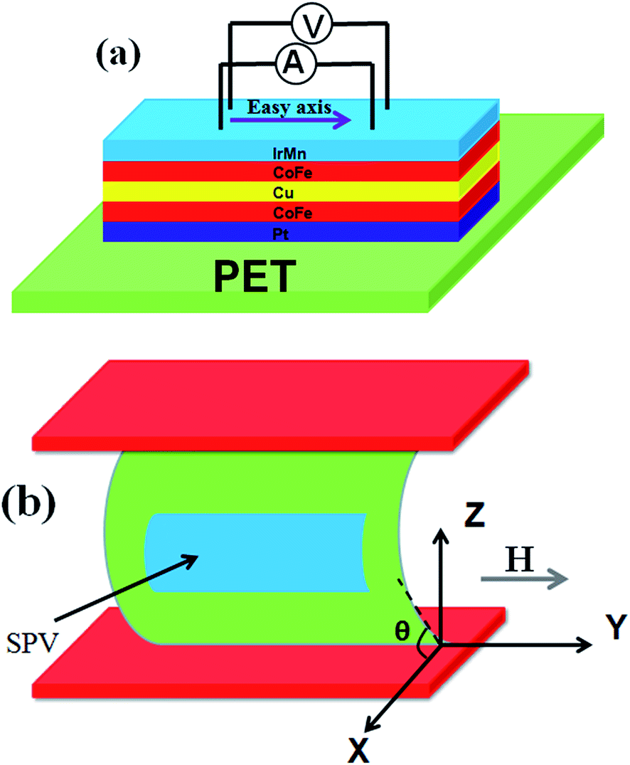 | ||
| Fig. 1 (a) Schematic diagram of the PET/SPV heterostructure. (b) Fixing device of the PET/SPV heterostructure. | ||
3. Results and discussion
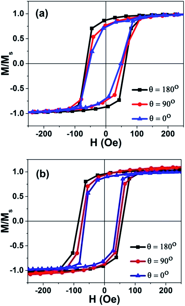
Fig. 2(a) shows the AFM image of a PET substrate. The root mean square roughness value of PET is calculated to be 0.596 nm in an area of 1 × 1 μm2, which is comparable with that of the thermally oxidized Si substrate of about 0.60 nm. Fig. 2(b) presents the M–H loops measured at different angle α. The angle α is defined by the angle between y axis and the in-plane magnetic field H as shown in the inset of Fig. 2(b). It is convinced that the easy axis of the SPV is orientated in y axis after the fabrication under the external field of 100 Oe. As shown in Fig. 3(a) and (b), we measured the M–H loops of Co90Fe10 (5)/PET and Co90Fe10 (5)/IrMn (8)/PET under different bending angle. We can see that the coercivity increases slightly with the bending angle increasing, but the exchange bias remains unchanged. Co90Fe10 has a positive magnetostriction coefficient. For a Co90Fe10 film, applying compressive strain in xz-plane will produce a tensile strain in y-axis, which makes the magnetic easy axis parallel to the easy axis of the unbent state.22 Therefore, the uniaxial anisotropy constant increases. For the applied tensile strain in xz-plane, we get the external stress induced magnetic anisotropy and the uniaxial anisotropy coefficient Ku = MsHk/2, where t is the thickness of the substrate, ρ the curvature radius of the substrate after bending, Y the Young's modulus, ν the Poisson ratio, λ the saturation magnetostriction coefficient, and Hk the magnetic anisotropy field. To simplify the calculation model, we take the PET film as a circular arc. According to the formula
  , the strain ε increases monotonically with the bending angles θ as shown in Fig. 2(c). If we set Hk = 16 Oe, Heb = 38 Oe, λ = 83 ppm, φ = 1°, ν = 0.3 for metal, Y = 2.1 × 10¹², and Ms = 1900 emu cm−3,23,24 we can get Ku = 1.52 × 10⁴ erg cm−3, Kσ = 2.25 × 10⁵ erg cm−3 (θ = 0°), Kσ = 1.5 × 10⁵ erg cm−3 (θ = 30°), Kσ = 0.75 × 10⁵ erg cm−3 (θ = 60°). Kσ is larger than Ku, which means the final easy axis will be along the applied tensile strain in xz-plane. Therefore, the coercivities of Co90Fe10 and Co90Fe10/IrMn increase as shown in Fig. 3(a) and (b). For the antiferromagnetic IrMn layer, stress has little effect on its magnetic properties and consequent exchange bias.17
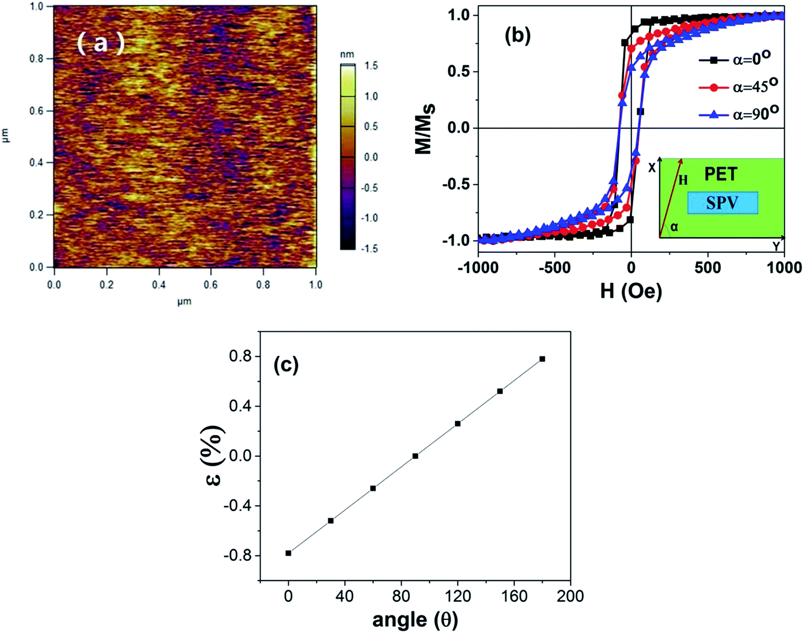 | ||
| Fig. 2 (a) AFM image of the PET substrate. (b) The M–H loops measured at different angle α. α is defined by the angle between y axis and the in-plane magnetic field H as shown in the inset. (c) Dependence of strain on the bending angle θ. | ||
 | ||
| Fig. 3 (a) M–H loops of Co90Fe10 measured at different bending angle θ. (b) M–H loops of Co90Fe10/IrMn measured at different bending angle θ. | ||
The GMR curves of the as-deposited SPVs on both PET and SiO2 substrates are shown in Fig. 4(a). The SPV on the PET substrate shows a GMR of 1.28%, which is much lower than 2.95% of the one on the SiO2 substrate due to the amorphous PET. To study the effect of strain on the magnetic properties of the PET/SPV heterostructure, we measured the GMR curves with applying different bending angle θ. The θ ranges of 0–90° and 90–180° correspond to tensile strain and compressive strain, respectively. As shown in Fig. 4(b), when the bending angle θ is set to 0°, 90° and 180°, the GMR is measured to be 0.64%, 1.28% and 2.08%, respectively. To verify the GMR repeatability of the devices under strain, we measure the GMR after 500 times bending (from 0° to 180°). As shown in Fig. 4(c), the GMR almost remains the same (θ = 0°, GMR = 0.71%; θ = 90°, GMR = 1.21%; θ = 180°, GMR = 2.20%) as that measured during the first bending process. Fig. 4(d) presents the GMR dependence on the bending angle θ. It is obvious that the GMR increases monotonically with the bending angle θ increasing from 0° to 180°. According to the effect of strain on the Co90Fe10 and IrMn films, the magnetic anisotropy of both the free layer and pinned layer increases with the increase of the bending angle θ, and the GMR shows a monotonic increasing. It is worthy to note that the GMR at θ = 90° of 1.28% after applying stress is close to that of the as-deposited one of 1.17%. The recoverable GMR of the SPV on PET indicates a volatile strain from flexible substrate and the corresponding volatile GMR change. Furthermore, when the sample is bent from the compressive state (θ = 180°) to tensile state (θ = 0°), GMR will be suppressed by strain from 2.08% to 0.64%. The GMR of the SPV shows a monotonic change by more than a factor of 3.
 | ||
| Fig. 4 (a) GMR curves of the PET/SPV and SiO2/SPV. (b) GMR curves of the PET/SPV heterostructure under different bending angle θ. (c) GMR curves of the PET/SPV heterostructure under different bending angle θ after 500 times bending. (d) GMR dependence on the bending angle θ. | ||
To further understand the effect of strain on the magnetic properties of the PET/SPV heterostructure, we performed numerical simulations on the free layer and the pinned layer based on the Stoner–Wohlfarth model.25 The total energy E1 of the pinned layer is given by
E1 = −Ku![[thin space (1/6-em)]](https://www.rsc.org/images/entities/char_2009.gif) cos2θ + Kσcos2θ − Kebcosθ − MsHcos(θ − ψ) cos2θ + Kσcos2θ − Kebcosθ − MsHcos(θ − ψ)
| (1) |
 . By deriving formula (1) and transforming its first order derivation, we have got the simulated magnetization curves of the pinned layer, as shown in Fig. 5(a). With the bending angle increasing from 0° to 180°, i.e. from tensile strain to compressive one, the exchange bias almost remains unchanged and the coercivity increases, which could interpret the effect of strain on the magnetic properties of the PET/SPV heterostructure. For exchange bias system, with the magnetic field parallel to the easy axis, the compressive strain perpendicular to the easy axis will enhance the uniaxial anisotropy and lead the ferromagnetic moments to orientate to the easy axis. While the tensile strain has the opposite effect on the exchange bias system, the total energy E2 of free layer is given by
|
E2 = −Kucos2θ + Kσcos2θ − MsHcos(θ − ψ)
| (2) |
 | ||
| Fig. 5 Simulated M–H loops of the pinned layer (a) and the free layer (b) with different bending angle θ. | ||
We have accordingly got the simulated magnetization curves of the free layer, as shown in Fig. 5(b). The squareness of the hysteresis loops increases to 1 while the strain changes from the tensile one to the compressive one, which suggests the uniaxial anisotropy increasing and the ferromagnetic moments orientating to the easy axis. According to the numerical simulations, the strain has similar effect on the ferromagnetic moments of the free layer and the pinned layer. The GMR depends on the relative orientation of the ferromagnetic moments of the two ferromagnetic layers separated by a nonmagnetic layer.26–28 When we put a compressive strain on the PET/SPV heterostructure, the uniaxial anisotropy of the pinned layer and the free layer increases, driving the ferromagnetic moments of both magnetic layers to orientate to the easy axis, which results in the GMR increase. The interpretation is also consistent with the change of GMR in the PET/SPV heterostructure under tensile strain.
The considerable change of the GMR for the PET/SPV heterostructure offers a possibility to generate a GMR signal by controlling the bending angle θ. Here, we employ three experimental values of the GMR (θ = 0°, GMR = 0.64%; θ = 90°, GMR = 1.28%; θ = 180°, GMR = 2.08%) to simulate the process of generating a GMR signal by bending angle. Fig. 6(a) and (b) show the time dependence of the bending angle θ and the GMR. By applying a different bending angle θ on the substrate, the GMR increases immediately with the bending angle θ increasing from 0° to 180°. When the bending angle subsequently decreases back to 0°, the PET/SPV heterostructure returns to its initial state simultaneously, and the GMR decreases correspondingly. It is worthy to be mentioned that the GMR keeps constant at a fixed bending angle. Therefore, the GMR of SPV/PET heterostructure exhibits an analogous “high/low” behavior with the bending angle switching on and off alternatively. In addition, signal imitation usually uses sine or cosine wave functions or their Fourier series to generate different kinds of signals. We employ two experimental values of GMR (θ = 0°, GMR = 0.64%; θ = 180°, GMR = 2.08%) to simulate the process of generating GMR signal by bending angle. First, we fit the time dependence of the sawtooth wave functional bending angle by 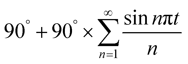 , in which time t is independent variable and the bending angle θ is dependent one, as shown in Fig. 6(c). Then, the GMR changes under the bending angle which changes with time. So we get the time dependence of the GMR shown in Fig. 6(d). We achieve the control of the GMR under a sawtooth wave functional bending angle. As shown in Fig. 6(c), with the increasing n, the signal θ becomes closer to a sawtooth wave function and the peak (valley) tends to be sharper. From Fig. 6(d), as the angle θ increases to 180°, the GMR changes immediately from the starting point to the maximum one, then goes down slowly. When the angle θ slowly goes back to zero, the GMR simultaneously decreases to the minimum value. When the angle θ increases from zero to 180°, the GMR increases correspondingly. Since the GMR is tuneable via the angle θ, an “N” shaped GMR signal can be obtained by applying Fourier series of the sawtooth wave functional angle θ. According to the simulation, the PET/SPV heterostructure may be a promising candidate for a magnetic signal generating device controlled by an electric field with low power consumption.
 | ||
| Fig. 6 (a) and (b) The time dependence of the bending angle θ and the GMR. (c) The time dependence of the sawtooth wave functional bending angle θ imitated by its Fourier series. (d) The time dependence of the GMR under the sawtooth wave function bending angle θ without external magnetic field. | ||
4. Conclusion
In summary, a top-pinned SPV was fabricated on the amorphous PET substrate. Due to the strain-mediated magnetic anisotropy changes of both magnetic layers, the GMR of the SPV shows a monotonic change by more than a factor of 3, which can be explained by the Stoner–Wohlfarth model. By controlling the bending angle θ, the GMR signal can be generated. The study opens a new way to design magnetoelectric devices based on the strain-modulated GMR changes.Acknowledgements
This work was supported by the National Basic Research Program of China (Grant Nos. 2015CB921502), the National Natural Science Foundation of China (Grant Nos. 51371024, 51325101, 51271020, 51471029 and 51671019) and the State Key Laboratory for Advanced Metals and Materials (No. 2016Z-25).Notes and references
- J. A. Rogers, Z. Bao, K. Baldwin, A. Dodabalapur, B. Crone, V. R. Raju, V. Kuck, H. Katz, K. Amundson, J. Ewing and P. Drzaic, Proc. Natl. Acad. Sci. U. S. A., 2001, 98, 4835–4840 CrossRef CAS PubMed.
- G. Gustafsson, Y. Cao, G. M. Treasy, F. Klavetter, N. Colaneri and A. J. Heeger, Nature, 1992, 357, 477–479 CrossRef CAS.
- H. Klauk, Nat. Mater., 2007, 6, 397–398 CrossRef CAS PubMed.
- M. Kaltenbrunner, T. Sekitani, J. Reeder, T. Yokota, K. Kuribara, T. Tokuhara, M. Drack, R. Schwodiauer, I. Graz, S. Bauer-Gogonea, S. Bauer and T. Someya, Nature, 2013, 499, 458–463 CrossRef CAS PubMed.
- G. A. Salvatore, N. Munzenrieder, T. Kinkeldei, L. Petti, C. Zysset, I. Strebel, L. Buthe and G. Troster, Nat. Commun., 2014, 5, 2982 Search PubMed.
- F. C. Krebs, S. A. Gevorgyan and J. Alstrup, J. Mater. Chem., 2009, 19, 5442–5451 RSC.
- Z. Y. Fan, H. Razavi, J.-W. Do, A. Moriwaki, O. Ergen, Y. L. Chueh, P. W. Leu, J. C. Ho, T. Takahashi, L. A. Reichertz, S. Neale, K. Yu, M. Wu, J. W. Ager and A. Javey, Nat. Mater., 2009, 8, 648–653 CrossRef CAS PubMed.
- W. L. Leong, N. Mathews, B. Tan, S. Vaidyanathan, F. Dotzand and S. Mhaisalkar, J. Mater. Chem., 2011, 21, 5203–5214 RSC.
- S. J. Kim and J. S. Lee, Nano Lett., 2010, 10, 2884–2890 CrossRef CAS PubMed.
- K. J. Baeg, D. Khim, J. Kim, B. D. Yang, M. Kang, S. W. Jung, I. K. You, D. Y. Kim and Y. Y. Noh, Adv. Funct. Mater., 2012, 22, 2915–2926 CrossRef CAS.
- M. A. Khan, U. S. Bhansali and H. N. Alshareef, Adv. Mater., 2012, 24, 2165–2170 CrossRef CAS PubMed.
- R. H. Kim, H. J. Kim, I. Bae, S. K. Hwang, D. B. Velusamy, S. M. Cho, K. Takaishi, T. Muto, D. Hashizume, M. Uchiyama, P. André, F. Mathevet, B. Heinrich, T. Aoyama, D.-E. Kim, H. Lee, J.-C. Ribierre and C. Park, Nat. Commun., 2014, 5, 3583 Search PubMed.
- Y. Chen, Y. F. Mei, R. Kaltofen, J. I. Mönch, J. Schumann, J. Freudenberger, H. Klauß and O. G. Schmidt, Adv. Mater., 2008, 20, 3224–3228 CrossRef CAS.
- C. Barraud, C. Deranlot, P. Seneor, R. Mattana, B. Dlubak, S. Fusil, K. Bouzehouane, D. Deneuve, F. Petroff and A. Fert, Appl. Phys. Lett., 2010, 96, 072502 CrossRef.
- W. R. Che, X. F. Xiao, N. Y. Sun, Y. Q. Zhang, R. Shan and Z. G. Zhu, Appl. Phys. Lett., 2014, 104, 262404 CrossRef.
- G. H. Dai, Q. F. Zhan, Y. W. Liu, H. L. Yang, X. S. Zhang, B. Chen and R. W. Li, Appl. Phys. Lett., 2012, 100, 122407 CrossRef.
- X. S. Zhang, Q. F. Zhan, G. H. Dai, Y. W. Liu, Z. H. Zuo, H. L. Yang, B. Chen and R. W. Li, Appl. Phys. Lett., 2013, 102, 022412 CrossRef.
- J.-H. Kwon, W.-Y. Kwak, H. Y. Choi, G. H. Kim and B. K. Cho, J. Appl. Phys., 2015, 117, 17E120 CrossRef.
- T. Duenas, A. Sehrbrock, M. Löhndorf, A. Ludwig, J. Wecker, P. Grünberg and E. Quandt, J. Magn. Magn. Mater., 2002, 242, 1132–1135 CrossRef.
- S. H. Florez and R. D. Gomez, IEEE Trans. Magn., 2003, 39, 3411–3413 CrossRef CAS.
- G. Anderson, Y. M. Huai and L. Miloslawsky, J. Appl. Phys., 2000, 87, 6989–6991 CrossRef CAS.
- Y. J. Yang, M. M. Yang, Z. L. Luo, H. L. Huang, H. B. Wang, J. Bao, C. S. Hu, G. Q. Pan, Y. P. Yao, Y. K. Liu, X. G. Li, S. Zhang, Y. G. Zhao and C. Gao, Appl. Phys. Lett., 2012, 100, 043506 CrossRef.
- T. L. Jin, L. Hao, J. W. Cao, M. F. Liu, H. G. Dang, Y. Wang, D. P. Wu, J. M. Bai and F. L. Wei, Appl. Phys. Express, 2014, 7, 043002 CrossRef.
- J. McCord, R. Schäfer, R. Mattheis and K.-U. Barholz, J. Appl. Phys., 2003, 93, 5491 CrossRef CAS.
- E. C. Stoner and E. P. Wohlfarth, Philos. Trans. R. Soc., A, 1948, 240, 599 CrossRef.
- R. E. Camley and J. Barnaś, Phys. Rev. Lett., 1989, 63, 664 CrossRef CAS PubMed.
- J. Barnaś, O. Baksalary and A. Fert, Phys. Rev. B: Condens. Matter Mater. Phys., 1997, 56, 6079 CrossRef.
- C. Blaas, P. Weinberger, L. Szunyogh, J. Kudrnovský, V. Drchal, P. M. Levy and C. Sommers, Eur. Phys. J. B, 1999, 9, 245 CrossRef CAS.
| This journal is © The Royal Society of Chemistry 2016 |