
Controlled synthesis of N-doped carbon spheres with different morphologies for supercapacitors
Zuosong Suna,
Shaodian Shen*a,
Limeng Maa,
Dongsen Maoa and
Guanzhong Lu*ab
aResearch Institute of Applied Catalysis, School of Chemical and Environmental Engineering, Shanghai Institute of Technology, Shanghai 201418, China. E-mail: mingtiansit@163.com; gzhlu@ecust.edu.cn; Fax: +86-21-64252923
bKey Laboratory for Advanced Materials and Research Institute of Industrial Catalysis, East China University of Science and Technology, Shanghai 200237, China
First published on 19th October 2016
Abstract
A facile and general strategy has been developed for synthesizing nitrogen doped mesoporous carbon nanospheres (NMCs), newly nitrogen doped lychee exocarp-like mesoporous carbon spheres (NLEMCs) and nitrogen doped core–shell mesoporous carbon spheres (NCSMCs). In this soft templating strategy, cetyltrimethylammonium chloride is used as the template while m-aminophenol is employed as a nitrogen source. All three types of N-doped carbon nanospheres, with uniform spherical morphologies, abundant mesoporous structures, high N-doped content, high surface areas and large pore volumes, exhibit specific capacitances of 262.4 F g−1, 323.2 F g−1 and 247.06 F g−1, respectively, at a current density of 0.2 A g−1 in 6 M KOH electrolyte solution. NLEMCs with a new lychee exocarp-like spherical morphology show an excellent electrochemical performance as a supercapacitor electrode, which may be due to there being more active sites, caused by the high surface area.
1. Introduction
In recent years, carbon materials1–7 have been reported and used in many fields. Especially, mesoporous carbon spheres (MCs) have attracted great attention due to their unique properties, such as low cost, good conductivity, stable physicochemical properties, and porous texture. These excellent properties mean that MCs have potential applications in a wide variety of fields, including in catalysts,8–10 CO2 adsorption,11,12 lithium-ion batteries,13 drug delivery,14,15 and supercapacitors.16–25 Particularly, with growing shortages of traditional energy sources, and global warming, many efforts have been made to develop environmental energy storage device technologies to meet the ever-increasing demands of energy applications.26 MCs, which offer high specific capacitance, are considerably desirable for supercapacitors, owing to their mesoporous structure with lower transport resistance. However, there are few reports of MCs with excellent properties in capacitance.The strategy to achieve high electrochemical capacitance is to incorporate heteroatoms into the carbon framework, such as N, B, S, and P. It has been reported that doped nitrogen is an effective way to improve the properties of carbon. The doping of nitrogen, as an electron donor to attract protons, gives carbon excellent characteristics, including adding pseudocapacitance, elevating electronic conductivity, increasing wettability and decreasing contact resistance. Past publications have shown that the doped nitrogen can improve the electrochemical properties of carbon materials to a large degree. Zhou et al. reported a hard template approach for the preparation of nitrogen-doped hierarchical porous carbon materials (NHPCs) with a high capacitance of 271.5 F g−1.27 Xu and co-workers synthesized N-doped porous carbon spheres through a low temperature defluorination treatment with an organic alkali followed by high temperature carbonization, although the specific surface area (523 m2 g−1) and capacitance (190 F g−1) of the N-doped porous carbon spheres is relatively low.28 However, there are few reports about carbon materials with special pore morphology and high N doped content in capacitance.
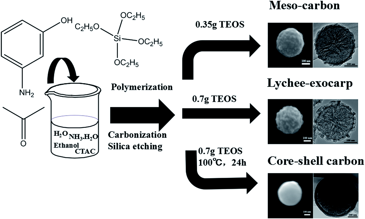
In this paper, we report a general and facile synthesis process (Scheme 1) for nitrogen doped carbon materials, including N doped mesoporous carbon spheres (NMCs), N doped lychee exocarp-like mesoporous carbon spheres (NLEMCs) and N doped core–shell mesoporous carbon spheres (NCSMCs), using cetyltrimethylammonium chloride as template, and m-aminophenol and formaldehyde as nitrogen and carbon precursors, respectively. The obtained NMCs, NLEMCs and NCSMCs possess high surface areas, large pore sizes, and high N doped content. Particularly, NLEMCs exhibit good electrochemical performance as supercapacitor electrodes, with a specific capacitance of 323.2 F g−1 at 0.2 A g−1 current density and good cycling stability in 6 M KOH electrolyte solution.
 | ||
| Scheme 1 Illustration of the synthesis route for NMCs, NLEMCs, and NCSMCs. | ||
2. Experimental section
2.1. Synthesis of N-doped mesoporous carbon spheres (NMCs)
Nitrogen doped mesoporous carbon spheres (NMCs) were prepared by adding 0.25 g cetyltrimethylammonium chloride (CTAC) and 0.12 g ammonia aqueous solution (NH4OH, 25 wt%) into a mixture of ethanol and water, and stirring for 30 min. Subsequently, 0.2 g m-aminophenol was added and continually stirred for 30 min. Then 0.35 g tetraethyl orthosilicate (TEOS) and 0.22 g formaldehyde solution were added to the above solution and then stirred for 24 h at 30 °C. The solid product was centrifuged and then air-dried at 80 °C for 12 h. The obtained product was carbonized in a tubular furnace at 300 °C and 600 °C, consecutively, for 2 h under an N2 atmosphere with a heating rate of 1 °C min−1, making sure the precursors of the NMCs were completely converted. 20% HF solution (20 ml) was added for the HF etching. Lastly, deionized water was used to wash the samples which were then dried at 100 °C in an oven for 12 h.2.2. Synthesis of N-doped lychee exocarp-like mesoporous carbon spheres (NLEMCs)
Nitrogen doped lychee exocarp-like mesoporous carbon spheres (NLEMCs) were prepared by adding 0.25 g cetyltrimethylammonium chloride (CTAC) and 0.12 g ammonia aqueous solution (NH4OH, 25 wt%) to a mixture of ethanol (10 g) and water (20 g), and then stirring for 30 min. Subsequently, 0.2 g m-aminophenol was added and continually stirred for 30 min. Then 0.7 g tetraethyl orthosilicate (TEOS) and 0.22 g formaldehyde solution were added to the above solution and stirred for 24 h at 30 °C. The solid product was centrifuged and then air-dried at 80 °C for 12 h. The obtained product was carbonized in a tubular furnace at 300 °C and 600 °C, consecutively, for 2 h under an N2 atmosphere with a heating rate of 1 °C min−1, making sure that the precursors of the NLEMCs were completely converted. 20% HF solution (20 ml) was added for the HF etching. Lastly, deionized water was used to wash the samples which were then dried at 100 °C in an oven for 12 h.2.3. Synthesis of N-doped core–shell mesoporous carbon spheres (NCSMCs)
Firstly, 0.25 g cetyltrimethylammonium chloride (CTAC) and 0.12 g ammonia aqueous solution (NH4OH, 25 wt%) were dissolved in a mixture of ethanol (10 g) and water (20 g) which was stirred for 30 min. Subsequently, 0.2 g m-aminophenol was added and continually stirred for 30 min. Then 0.7 g tetraethyl orthosilicate (TEOS) and 0.22 g formaldehyde solution were added to the reaction solution and then stirred for 24 h at 30 °C. The reaction mixture was further heated for 24 h at 100 °C under a static condition in a Teflon-lined autoclave. The solid product was centrifuged and then air-dried at 80 °C for 12 h. The obtained product was carbonized in a tubular furnace at 300 °C and 600 °C, consecutively, for 2 h under an N2 atmosphere with a heating rate of 1 °C min−1, making sure that the precursors of the NCSMCs were completely converted. 20% HF solution (20 ml) was added for the HF etching. Lastly, deionized water was used to wash the samples which were then dried at 100 °C in an oven for 12 h.2.4. Electrochemical measurements
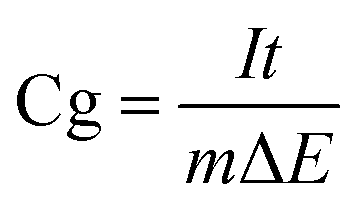
Electrochemical tests were performed on a CHI 660E, a potentiostat controlled via computer (CH Instrument, Inc.) with a standard three-electrode cell. Nickel foam serving as the substrate for the deposited sample is the working electrode, platinum wire and Hg/HgO are the counter electrode and reference electrode, respectively. For a working electrode, 80 wt% active catalyst, 10 wt% acetylene black and 10 wt% polytetrafluoroethylene were mixed to a homogeneous slurry, which was successfully pressed onto a nickel foam (an area of 1 cm2) and then dried at 120 °C in an oven for 10 h. The mass of the active catalyst loaded in the working electrode was about 5 mg. In the experiment, all of the tests were done at 25 °C with 6 M KOH as electrolyte. The potentials for electrochemical tests are reported relative to a reference electrode of Hg/HgO and the cycling potential window was confined between 0 V and −1 V. The gravimetric specific capacitance, Cg, was calculated according to the equation with the charge–discharge curves discharge portion as following:where I, t, ΔE and m are the applied current, time of discharge, voltage change, and mass of active catalyst, respectively.
2.5. Characterization
The morphology of the carbon nanospheres was examined via field-emission scanning electron microscopy (FESEM) with a Quanta 200 FEG electron microscope, which is operated at 5 kV. Transmission electron microscopy (TEM) tests were performed using a JEOL JEM 2100 system, and operated at 200 kV. N2 sorption isotherms were performed at 77 K via a Micromeritics ASAP 2020 system. Before the tests, the carbon nanospheres were dried at 200 °C under vacuum for 10 h. The specific surface area was calculated via the method of Brunauer–Emmett–Teller (BET). By the Barrett–Joyner–Halenda model (BJH), pore volume and pore size distributions can be obtained from the isotherm adsorption branches. The total pore volumes (V) were calculated from the adsorbed amount at P/P0 at about 0.995. The composition of the sample was determined using XPS (Thermo Scientific ESCALAB 250Xi).3. Results and discussion
All three types of NMCs were synthesized using m-aminophenol as a nitrogen precursor, cetyltrimethylammonium chloride as a template, and TEOS as inorganic precursor, with subsequent carbonization and the removal of silica. The SEM and TEM images of the three types of NMCs are shown in Fig. 1. When the amount of TEOS is 0.35 g, we can obtain nitrogen doped mesoporous carbon spheres (NMCs) with uniform spherical morphology (Fig. 1a). Fig. 1a shows that the NMCs of 330 nm diameter have a spherical morphology. Meanwhile, we can see that the NMCs exhibit a rough surface and stable structure. Fig. 1d, showing the TEM morphology of the NMCs, also reveals that the NMCs have uniform spherical morphology, rough surface and stable structure. The results of both SEM and TEM images show that the NMCs have uniform spherical morphology, rough surface and stable structure. As the amount of TEOS increased to 0.7 g, new NLEMCs with a special morphology were obtained. NLEMCs with uniform spherical morphology are presented in Fig. 1b, from which we can see that lots of protruding points are on the surface of the NLEMCs. In this article, we named the new-style N-doped mesoporous carbon spheres with a lot of protruding points as N-doped lychee exocarp-like mesoporous carbon spheres (NLEMCs). The spherical morphology of NLEMCs was well retained after carbonization and silica removal (see Fig. 1b). The diameter of the NLEMCs is 400 nm. The TEM image of the NLEMCs shows that NLEMCs have uniform spherical morphology, are mesoporous and have lots of protruding points on the surface as seen in Fig. 1e. Compared to NMCs, NLEMCs have more protruding points on the surface, a bigger particle size and brighter image according to the results of SEM and TEM images. These differences were produced due to the different amounts of TEOS. When a higher content of TEOS was added into the experiment, more silica template was produced. After carbonization and silica etching, NLEMCs have a more mesoporous structure. The transformation lead to NLEMCs with a brighter image, more protruding points on the surface and bigger particle size. The brighter TEM image of the NLEMCs may show that NLEMCs have a more porous structure. NCSMCs with a smooth surface and uniform spherical morphology were obtained, presented in Fig. 1c. Fig. 1c shows well defined spheres of about 420 nm in diameter. Fig. 1f also shows NCSMCs with well defined spheres of about 420 nm in diameter. The core–shell structure can be clearly observed in Fig. 1f. The wall thickness is about 40 nm and the yolk particle size is about 360 nm. The NCSMCs have a more smooth surface, a core–shell structure and a bigger particle size, compared to NLEMCs. The transformation must be caused by hydrothermal treatment in the experiment. | ||
| Fig. 1 SEM and TEM images of NMCs (a and d); NLEMCs (b and e); and NCSMCs (c and f). | ||
The N2 adsorption/desorption isotherms of all three types of NMCs display typical type-IV hysteresis in Fig. 2a because of the presence of mesopores. In Table 1, the BET surface areas of the NMCs, NLEMCs and NCSMCs are 744.18, 1126.11 and 434.53 m2 g−1 and the pore volumes are 0.63, 1.09 and 0.55 cm3 g−1, respectively. NLEMCs have the biggest pore volume and NCSMCs have the smallest pore volume, in agreement with the results of the TEM. Fig. 2b shows the corresponding pore size distribution curves of the NMCs, NLEMCs and NCSMCs, and the average pore size is 2 nm.
 | ||
| Fig. 2 N2 adsorption/desorption isotherms (a), and pore size distribution of NMCs, NLEMCs and NCSMCs (b). | ||
The XRD patterns reveal that all three types of NMCs possess an amorphous nature (Fig. 3a). The chemical composition and the bonding configuration of the materials can be characterized via X-ray photoelectron spectroscopy (XPS) as a powerful technique for the characterization of elemental composition and bonding configuration in materials. Fig. 3b shows the XPS survey spectra of NMCs, NLEMCs and NCSMCs, which shows three peaks assignable to C1s, N1s and O1s indicating the high purity of carbon. The surface chemistry of the NMCs was dominated by carbon, oxygen and nitrogen. The content of nitrogen in the NMCs, NLEMCs and NCSMCs is 5.37, 7.59 and 8.24 wt%, as listed in Table 1. The C1s and N1s XPS peaks are fitted to gain more insight into the structure of carbon and nitrogen in the three types of NMCs. The C1s XPS spectra of the sample can be decomposed into four Gaussian peaks, as shown in Fig. 3c. The peak at the bonding energy of about 284.5 eV represents the graphite like C–C bond, named as C1. C2 and C3 with bonding energies of 285.1 and 286.2 eV represent the C–N bonds of different types.29–31 The other peak at 289 eV (C4), was identified to originate from the O–C![[double bond, length as m-dash]](https://www.rsc.org/images/entities/char_e001.gif) O bonds.32 The N1s spectra of the NMCs, NLEMCs and NCSMCs are presented in Fig. 3d, which can be divided into three peak-types representing three electronic states of the nitrogen atom. The peaks with bonding energies of 398.1 eV, 399.5 eV and 400.7 eV can be characterized as pyridinic-type N (N-6), pyrrolic-type N (N-5), quaternary-type N (N-Q), consistent with the C1s spectra. Similar nitrogen forms are in NMCs, NLEMCs and NCSMCs because of the same nitrogen precursor and carbonization temperature.
O bonds.32 The N1s spectra of the NMCs, NLEMCs and NCSMCs are presented in Fig. 3d, which can be divided into three peak-types representing three electronic states of the nitrogen atom. The peaks with bonding energies of 398.1 eV, 399.5 eV and 400.7 eV can be characterized as pyridinic-type N (N-6), pyrrolic-type N (N-5), quaternary-type N (N-Q), consistent with the C1s spectra. Similar nitrogen forms are in NMCs, NLEMCs and NCSMCs because of the same nitrogen precursor and carbonization temperature.
 | ||
| Fig. 3 XRD and XPS spectra of NMCs, NLEMCs and NCSMCs: XRD patterns (a), survey spectra (b), C1s spectra (c), N1s spectra (d). | ||
Raman spectra of the NMCs, NLEMCs and NCSMCs are shown in Fig. 4, from which it can be seen that the D bands are positioned at 1350 cm−1, whereas the G bands are positioned at 1590 cm−1. The D band is associated with structural defects and partially disordered structures in carbon materials, and the G band reflects the crystallinity of carbon. The ratio of ID/IG is associated with the degree of graphitization of carbon. The values of ID/IG for NMCs, NLEMCs and NCSMCs are 0.77, 0.82 and 0.86, respectively, indicating that NMCs and NCSMCs exhibit the highest and the lowest graphitization. The value of ID/IG, which increased with the increase of the doped nitrogen content in carbon, is proportional to the number of defect sites in carbon.
 | ||
| Fig. 4 Raman spectra of NMCs, NLEMCs and NCSMCs. | ||
NMCs, NLEMCs and NCSMCs act as active catalysts at different activation concentrations in a working electrode, and this was measured in 6 M KOH electrolyte solution via galvanostatic charge–discharge and cyclic voltammogram (CV). The CV curves of the NMCs, NLEMCs and NCSMCs are shown in Fig. 5a, c and e, and are obtained using a potentiostat (CHI 660E, CH Instrument, USA) with a three-electrode electrochemical cell at different scan rates, with a potential window from −1 to 0 V. The CV curves still retain rectangular-like shapes even up to 200 mV s−1, which indicates good capacitive performance of the three types of NMCs. From the results of the CV curves, it can be seen that the pseudocapacitance and electric double-layer capacitance may produce a capacitive response, relating to the heteroatom functionalities of the carbon materials. The character of the curves suggested that all of the materials are appropriate for use as the electrode of a supercapacitor. The method of galvanostatic charge–discharge is assumed to be the most accurate way to obtain the specific capacitances of all of the NMCs for a supercapacitor. Fig. 5b, d and f show the curves of galvanostatic charge–discharge at current densities from 0.2 to 5 A g−1. Three types of NMC-based supercapacitors exhibit a low voltage drop at a high density up to 5 A g−1, indicating a small equivalent series resistance, which reveals that these catalysts have an excellent rate performance.33 By the formula of C = It/mΔE, the specific capacitance of the NMCs, NLEMCs and NCSMCs is 262.4, 323.2 and 247.06 F g−1 at a current density of 0.2 A g−1. Through the comparison of the three types of NMCs, it can be clearly seen that NLEMCs show the higher specific capacitance than NMCs and NCSMCs at a current density of 0.2 A g−1. NLEMCs have the highest specific surface area, the largest pore volume and a special lychee exocarp-like structure resulting in the biggest specific capacitance. The capacitance of NLEMCs is higher than that of nitrogen-doped carbon/graphene electrode materials (289 F g−1).34 The results suggest that NLEMCs are an optimum candidate for supercapacitor electrode applications.
 | ||
| Fig. 5 CV curves and galvanostatic charge–discharge curves of NMCs (a and b), NLEMCs (c and d) and NCSMCs (e and f). | ||
Fig. 6a shows the specific capacitance of NMCs, NLEMCs and NCSMCs at current densities from 0.2 to 20 A g−1. The specific capacitance of NMCs, NLEMCs and NCSMCs all decrease sharply with increasing current density. Pseudocapacitance has weaker endurance than double layer capacitance at large current densities, which may result in the dramatically decreased rate capabilities of NMCs, NLEMCs and NCSMCs. Cycle performance is a significant factor for NMCs, NLEMCs and NCSMCs used as the electrode of a supercapacitor, and this is presented in Fig. 6b–d. The cycling stability of the three carbon material electrodes was examined using galvanostatic charge–discharge cycling at a current density of 5 A g−1. After 1000 cycles, the specific capacitances remain at about 85%, which demonstrates good cycle performance.
 | ||
| Fig. 6 Specific capacitance calculated from galvanostatic charge–discharge curves of NMCs, NLEMCs and NCSMCs (a); cycling stability measured for NMCs (b), NLEMCs (c) and NCSMCs (d). | ||
4. Conclusions
In summary, three types of mesoporous carbon spheres were prepared using cetyltrimethylammonium chloride as a template, and m-aminophenol and formaldehyde as nitrogen precursor and carbon precursor, respectively. The new-style N-doped lychee exocarp-like mesoporous carbon spheres have higher surface area (1126.11 m2 g−1) and higher pore volume (1.09 cm3 g−1) than those of NMCs (744.18 m2 g−1, 0.63 cm3 g−1) and NCSMCs (434.53 m2 g−1, 0.55 cm3 g−1). NLEMCs exhibit a high specific capacitance of 323.2 F g−1 at a current density of 0.2 A g−1 because of their high surface area, high pore volume, lychee exocarp-like structure and nitrogen functionalization.References
- Y. H. Cao, J. N. Huang, Y. H. Li, S. Qiu, J. R. Liu, A. Khasanov, M. A. Khan, D. P. Young, F. Peng, D. P. Cao, X. F. Peng, K. l. Hong and Z. H. Guo, Carbon, 2016, 109, 640 CrossRef CAS.
- Y. Lan, X. H. Cao, S. G. Zhao, K. Dai, X. R. Yan, G. Q. Zheng, C. T. Liu, C. Y. Shen and Z. H. Guo, Polymer, 2016, 97, 11 CrossRef CAS.
- L. Zhang, Q. H. Zhang, H. Y. Xie, J. Guo, H. L. Lyu, Y. G. Li, Z. G. Sun, H. Z. Wang and Z. H. Guo, Appl. Catal., B, 2017, 201, 470 CrossRef CAS.
- J. H. Zhu, M. J. Chen, Q. L. He, L. Shao, S. Y. Wei and Z. H. Guo, RSC Adv., 2013, 3, 22790 RSC.
- H. Yi, H. W. Wang, Y. T. Jing, T. Q. Peng, Y. R. Wang, J. Guo, Q. L. He, Z. H. Guo and X. F. Wang, J. Mater. Chem. A, 2015, 3, 19545 CAS.
- H. Liu, J. C. Gao, W. J. Huang, K. Dai, G. Q. Zheng, C. T. Liu, C. Y. Shen, X. R. Yan, J. Guo and Z. H. Guo, Nanoscale, 2016, 8, 12977 RSC.
- H. Liu, W. J. Huang, X. R. Yang, K. Dai, G. Q. Zheng, C. T. Liu, C. Y. Shen, X. R. Yan, J. Guo and Z. H. Guo, J. Mater. Chem. C, 2016, 4, 4459 RSC.
- Z. X. Zhang, J. T. Wang, W. C. Li, M. Wang, W. M. Qiao, D. H. Long and L. C. Ling, Carbon, 2016, 96, 608 CrossRef CAS.
- D. M. Zhu, H. B. Jiang, L. Zhang, X. L. Zheng, H. Y. Fu, M. L. Yuan, H. Chen and R. X. Li, ChemCatChem, 2014, 6, 2954 CrossRef CAS.
- Q. Yang, J. Zhang, L. Zhang, H. Y. Fu, X. L. Zheng, M. L. Yuan, H. Chen and R. X. Li, Catal. Commun., 2013, 40, 37 CrossRef CAS.
- N. N. Sun, C. G. Sun, J. J. Liu, H. Liu, C. E. Snape, K. X. Li, W. Wei and Y. H. Sun, RSC Adv., 2015, 5, 33681 RSC.
- N. P. Wickramaratne and M. Jaroniec, ACS Appl. Mater. Interfaces, 2013, 5, 1849 CAS.
- J. Zang, J. C. Ye, X. L. Fang, X. W. Zhang, M. S. Zheng and Q. F. Dong, Electrochim. Acta, 2015, 186, 436 CrossRef CAS.
- L. Wan, Q. F. Zhao, P. Zhao, B. He, T. Y. Jiang, Q. Zhang and S. L. Wang, Carbon, 2014, 79, 123 CrossRef CAS.
- P. Zhao, L. H. Wang, C. S. Sun, T. Y. Jiang, J. H. Zhang, Q. Zhang, J. Sun, Y. H. Deng and S. L. Wang, Eur. J. Pharm. Biopharm., 2012, 80, 535 CrossRef CAS PubMed.
- X. L. Fang, J. Zang, X. L. Wang, M. S. Zheng and N. F. Zheng, J. Mater. Chem. A, 2014, 2, 6191 CAS.
- Y. Q. Zhang, M. M. Jia, H. Y. Gao, J. G. Yu, L. L. Wang, Y. S. Zou, F. M. Qin and Y. N. Zhao, Electrochim. Acta, 2015, 184, 32 CrossRef CAS.
- Q. Zhang, L. Li, Y. L. Wang, Y. J. Chen, F. He, S. L Gai and P. P. Yang, Electrochim. Acta, 2015, 176, 542 CrossRef CAS.
- C. X. Guo and C. M. Li, Energy Environ. Sci., 2011, 4, 4504 CAS.
- L. Mao, Y. Zhang, Y. T. Hu, K. H. Ho, Q. Q. Ke, H. J. Liu, Z. Q. Hu, D. Zhao and J. Wang, RSC Adv., 2015, 5, 9307 RSC.
- D. Y. Guo, X. A. Chen, Z. P. Fang, Y. F. He, C. Zheng, Z. Yang, K. Q. Yang, Y. Chen and S. M. Huang, Electrochim. Acta, 2015, 176, 207 CrossRef CAS.
- Y. Fan, X. Yang, B. Zhu, P. Y. Liu and H. T. Lu, J. Power Sources, 2014, 268, 584 CrossRef CAS.
- H. J. Liu, W. J. Cui, L. H. Jin, C. X. Wang and Y. Y. Xia, J. Mater. Chem., 2009, 19, 3661 RSC.
- S. K. Kim, E. Jung, M. D. Goodman, K. S. Schweizer, N. Tatsuda, K. Yano and P. V. Braun, ACS Appl. Mater. Interfaces, 2015, 7(17), 9128 CAS.
- X. M. Ma, M. X. Liu, L. H. Gan, Y. H. Zhao and L. W. Chen, J. Solid State Electrochem., 2013, 17, 2293 CrossRef CAS.
- X. Y. Lai, J. E. Halpert and D. Wang, Energy Environ. Sci., 2012, 5, 5604 CAS.
- J. Zhou, Z. S. Zhang, W. Xing, J. Yu, G. X. Han, W. J. Si and S. P. Zhou, Electrochim. Acta, 2015, 153, 68 CrossRef CAS.
- B. Xu, S. F. Yue, N. Qiao, M. Chu and G. Wei, Mater. Lett., 2014, 131, 49 CrossRef CAS.
- J. P. Zhao, Z. Y. Chen, T. Yano, T. Ooie, M. Yoneda and J. Sakakibara, J. Appl. Phys., 2001, 89, 1634 CrossRef CAS.
- J. W. Jang, C. E. Lee, S. C. Lyu, T. J. Lee and C. J. Lee, Appl. Phys. Lett., 2004, 84(15), 2877 CrossRef CAS.
- L. H. Chan, K. H. Hong, D. Q. Xiao, T. C. Lin, S. H. Lai, W. J. Hsieh and H. C. Shih, Phys. Rev. B: Condens. Matter Mater. Phys., 2004, 70, 125408 CrossRef.
- Y. X. Wang, X. Z. Cui, Y. S. Li, L. S. Chen, H. R. Chen, L. X. Zhang and J. L. Shi, Carbon, 2014, 68, 232 CrossRef CAS.
- G. A. Ferrero, A. B. Fuertes and M. Sevilla, J. Mater. Chem. A, 2015, 3, 2914 CAS.
- M. Li and J. M. Xue, J. Mater. Chem. C, 2014, 118, 2507 CAS.
| This journal is © The Royal Society of Chemistry 2016 |