 Open Access Article
Creative Commons Attribution 3.0 Unported Licence
Guest-dependent single-ion magnet behaviour in a cobalt(II) metal–organic framework†
Julia
Vallejo
a,
Francisco R.
Fortea-Pérez
a,
Emilio
Pardo
*a,
Samia
Benmansour
a,
Isabel
Castro
a,
J.
Krzystek
b,
Donatella
Armentano
c and
Joan
Cano
*ad
aDepartament de Química Inorgànica, Instituto de Ciencia Molecular (ICMOL), Universitat de València, 46980 Paterna, València, Spain. E-mail: emilio.pardo@uv.es; joan.cano@uv.es
bNational High Magnetic Field Laboratory, Florida State University, Tallahassee, Florida 32310, USA
cDipartimento di Chimica e Tecnologie Chimiche, Università della Calabria, 87036, Arcavacata di Rende, Cosenza, Italy
dFundació General de la Universitat de València (FGUV), Spain
First published on 10th December 2015
Abstract
Single-ion magnets (SIMs) are the smallest possible magnetic devices for potential applications in quantum computing and high-density information storage. Both, their addressing in surfaces and their organization in metal–organic frameworks (MOFs) are thus current challenges in molecular chemistry. Here we report a two-dimensional 2D MOF with a square grid topology built from cobalt(II) SIMs as nodes and long rod-like aromatic bipyridine ligands as linkers, and exhibiting large square channels capable to host a large number of different guest molecules. The organization of the cobalt(II) nodes in the square layers improves the magnetic properties by minimizing the intermolecular interactions between the cobalt(II) centres. Moreover, the SIM behaviour was found to be dependent on the nature of the aromatic guest molecules. The whole process could be followed by single-crystal X-ray diffraction, providing comprehensive evidence of the putative role of the solvent guest molecules that leave a “fingerprint” on the 2D structures and thus, on the cobalt environment.
Introduction
Single-molecule magnets (SMMs),1,2 and more recently, also the related single-ion magnets (SIMs) – both showing potential applications as high-density magnetic memory and quantum computing devices in the emerging field of molecular spintronics3,4 – attract the attention of many groups working in the fields of Molecular Magnetism5 and Multifunctional Materials.6–8 Among them, SIMs have gained an especial relevance in recent years, and different examples with lanthanides9–13 and actinides,14–17 but also with first18–25 and third26 row transition metal ions have been reported.Because of their fascinating structures and, especially, the wide range of physical (optical, magnetic, electronic, etc.) and chemical properties (gas storage and separation, transport, catalysis, etc.) that they can exhibit, extended multidimensional porous coordination polymers, also known as metal-organic frameworks (MOFs),27–32 have also attracted the interest of many groups for the design of multifunctional materials.6 For example, the rich host–guest chemistry of spin crossover metal–organic frameworks (SCO-MOFs),33–35 which is related to the intrinsic porous character of MOFs,36,37 allows these systems to have excellent potential application in molecular magnetic recognition.38
Aiming at sticking together these two hot subjects in chemistry in the same material and also by the possible resulting properties, we designed the synthesis of a MOF built from the repetition of highly organized SIMs, referred to as SIM-MOF.39 Moreover, we have taken advantage of the intrinsic porosity of the compound to tune the slow magnetic relaxation effects of the SIM nodes. So, we chose a rod-like aromatic bipyridine ligand with a very long organic spacer, such as 1,4-bis(pyridine-4-ylethynyl)benzene40 (bpeb), capable of acting as a bis(monodentate)bridging ligand toward magnetically anisotropic high-spin cobalt(II) ions to: (i) yield square grid-type two-dimensional (2D) MOFs with a porous structure possessing relatively large channels occupied with potentially exchangeable aromatic guest molecules that would preclude for undesired layer interpenetration, and (ii) afford the appropriate ligand field for observing SIM behaviour while preventing any magnetic interaction among the SIM metal nodes41–43 (Scheme 1).
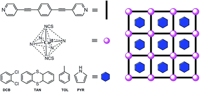 | ||
| Scheme 1 Ligand design approach to cobalt(II)-based SIM-MOFs for magnetic sensing of aromatic compounds. | ||
In this work, we report the synthesis, structural, high-frequency and high-field EPR (HFEPR) spectroscopic and magnetic characterisation, as well as theoretical calculations, of a novel series of two-dimensional (2D) MOFs of general formula [Co(bpeb)2(NCS)2]·nG, where G stands for the ortho-dichlorobenzene (DCB@1 with n = 7), thianthrene (TAN@1 with n = 4), toluene (TOL@1 with n = 6), and pyrrole (PYR@1 with n = 8) guest molecules. Compounds G@1 (G = DCB, TAN, TOL, and PYR) can be described as an extended array of nanostructured octahedral cobalt(II) SIMs, thus constituting one of the very first examples of SIM-MOFs.39,41–44 Interestingly, as a direct consequence of the replacement of the DCB guest molecules hosted in the channels of the original compound (DCB@1) along this unique series of adsorbates, tuning of the SIM behaviour takes place depending on the nature of the guest.
Results and discussion
Synthesis and X-ray crystal structure
Compound DCB@1 was first obtained as well-formed rectangular prisms by layering a methanol solution of CoII(NCS)2 over an ortho-dichlorobenzene/methanol solution (4![[thin space (1/6-em)]](https://www.rsc.org/images/entities/char_2009.gif) :
:![[thin space (1/6-em)]](https://www.rsc.org/images/entities/char_2009.gif) 1 v/v) of bpeb ligand (1
1 v/v) of bpeb ligand (1![[thin space (1/6-em)]](https://www.rsc.org/images/entities/char_2009.gif) :
:![[thin space (1/6-em)]](https://www.rsc.org/images/entities/char_2009.gif) 2 metal–ligand molar ratio) in an essay tube at room temperature (see Experimental section). Thereafter, TAN@1, TOL@1, and PYR@1 were obtained through a single-crystal-to-single-crystal (SC-SC) transformation by immersing crystals of DCB@1 for a week in the corresponding solvents thianthrene, toluene, and pyrrole, respectively (Table S1, ESI†).
2 metal–ligand molar ratio) in an essay tube at room temperature (see Experimental section). Thereafter, TAN@1, TOL@1, and PYR@1 were obtained through a single-crystal-to-single-crystal (SC-SC) transformation by immersing crystals of DCB@1 for a week in the corresponding solvents thianthrene, toluene, and pyrrole, respectively (Table S1, ESI†).
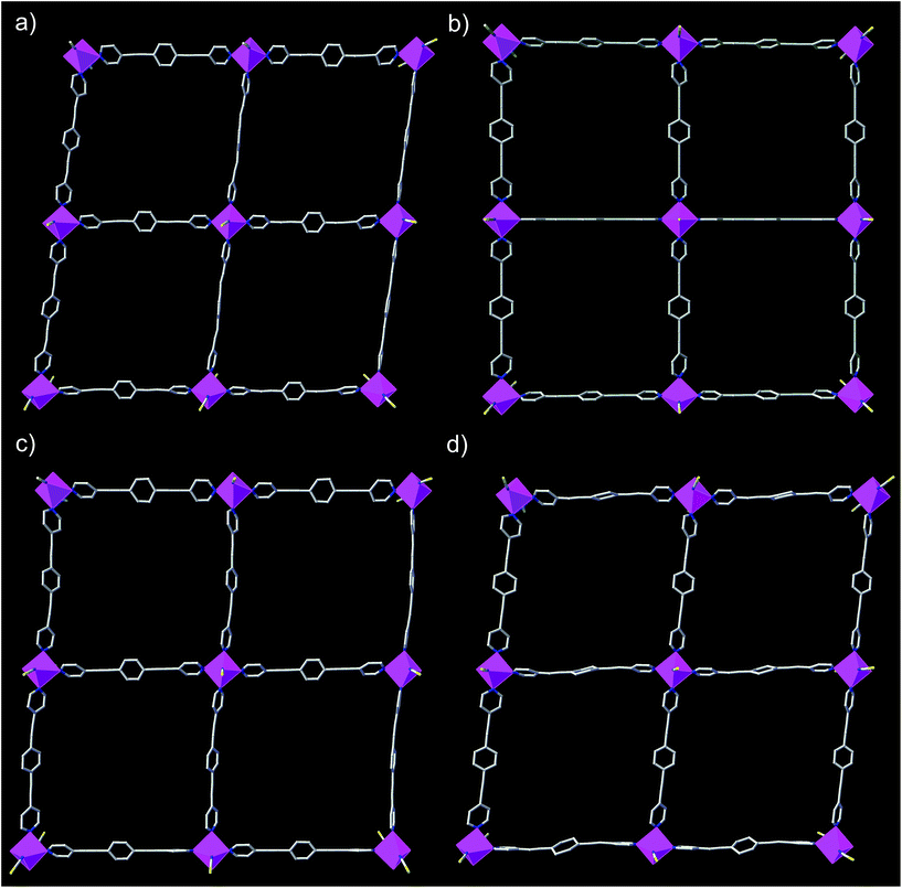
The structures of DCB@1, TAN@1, TOL@1, and PYR@1 were determined by X-ray diffraction on single crystals at 100 K (see Experimental section), showing that they are different polymorphs. All four compounds are made up of similar square grid flat layers of (44·62) net topology43–46 and free highly disordered solvent molecules (Fig. 1 and S1–S3, ESI†). However, the different nature of the guests hosted in the channels together with the intrinsic flexibility of the system, promote more or less severe distortions from the ideal square grid structure avoiding isostructurality (Fig. 1 and S3†). The estimated volumes of accessible solvent voids (Fig. S4†) are ca. 65% of the total unit cell volume for all four compounds (see ESI for details†).
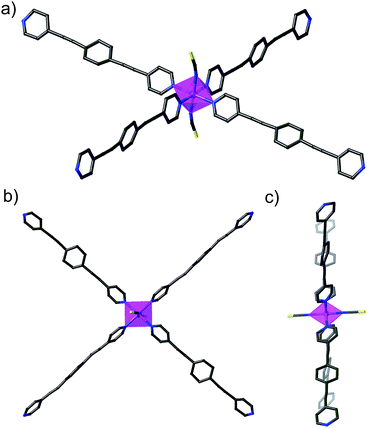
The cobalt(II) ions of DCB@1, TAN@1, TOL@1, and PYR@1 are located in the corners of each square grid and linked by the very long organic spacers acting as edges of the squares, as illustrated in Fig. 1, 2 and S3† for the parent compound of the series. In fact, the length of the rod-like bpeb bridging ligand in DCB@1, TAN@1, TOL@1, and PYR@1 results in the CoII ions in each square grid being very well isolated (see Table S2†). In contrast, neighbouring CoII ions belonging to adjacent layers are closer to each other [shortest intermetallic distances are in the range of 11.502(2)–11.760(2) Å] (see Table S2†) but still quite well isolated.
In all four compounds, each cobalt(II) ion is situated in a highly distorted six-coordinated octahedral environment, CoN6. The equatorial Co–N bond distances are somewhat larger than the axial Co–N bond distances (see Table S2†), all of them being typical of high-spin CoII ions. This leads to an overall tetragonal distortion (axial compression) of the octahedral metal environment (Fig. S5 and Table S2†). Interestingly, the nature of the guest induces severe distortions in the organic spacer conformation, which is also apparent in the structural dimensions of the square layers of DCB@1, TAN@1, TOL@1, and PYR@1 (Fig. 1 and S3†). The main structural variations along this series are related to the values of the dihedral angle between the terminal pyridine and central benzene rings (δ), resulting in distortions also in the values of the intralayer cobalt(II)–cobalt(II)–cobalt(II) angle (φ) (see Table S2†).
Ultimately, and as a consequence of these distortions, the environment of the cobalt(II) ions changes significantly from one compound to another, affording further proof of the flexibility of these systems. It can be envisaged that the reported guest-dependent structural changes may have a great influence on those physical properties strongly dependent of the metal coordination environment such as the dynamic magnetic properties of the cobalt(II) centres (see discussion below). In this regard, it should be highlighted that the reported crystal structures are collected at 100 K whereas dynamic magnetic properties are usually measured below 10 K. However, although small structural changes may take place between 10 and 100 K, the crystal structures show unambiguously that the nature of the guest molecule strongly modifies the cobalt(II) environment at 100 K, which must also apply below 10 K, even if temperature dependent structural changes may also occur.
Physical characterisation
The solvent content of DCB@1, TAN@1, TOL@1, and PYR@1 was determined by elemental (C, H, N, and S) analysis (see Experimental section) and further confirmed by thermogravimetric analysis (TGA) under a dry N2 atmosphere (Fig. S6†). The mass loss values are consistent with 7 DCB (DCB@1), 4 TAN plus 4 MeOH (TAN@1), 6 TOL (TOL@1), and 8 PYR (PYR@1) molecules per formula unit, which are in agreement with the formulas determined by elemental analysis (ESI†).The powder X-ray diffraction (PXRD) patterns of freshly prepared samples of DCB@1, TAN@1, TOL@1, and PYR@1 (measured as suspensions of the samples in the corresponding solvent solutions) are similar but not identical, and they are all consistent with the calculated ones (Fig. 3). These features confirm both that the bulk samples are isostructural to the crystals selected for single-crystal X-ray diffraction, and that the three adsorbates (TAN@1, TOL@1 and PYR@1) are different polymorphs of the original compound (DCB@1). The different degree of distortion in the organic spacer conformation – arising from the different nature of the guest molecule in each compound – lies at the origin of the lack of isostructurality.
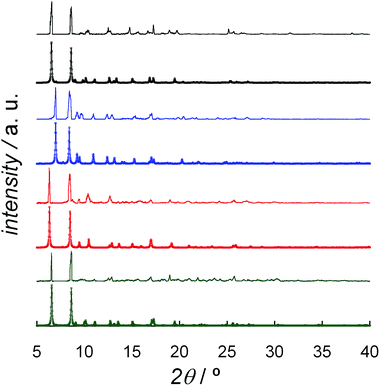 | ||
| Fig. 3 Experimental (top) and calculated (bottom) XRPD pattern profiles of DCB@1 (green), TAN@1 (red), TOL@1 (blue) and PYR@1 (black) in the 2θ range of 5.0–40.0° at 100 K. | ||
Finally, specific heat capacity measurements were carried out for DCB@1, TAN@1, TOL@1, and PYR@1 in the temperature range of 100.0–2.0 K. The lack of λ peaks for all compounds (Fig. S7†) suggests that no phase transition occurs below 100 K.
Static (dc) magnetic properties and HFEPR measurements
The magnetic properties of DCB@1, TAN@1, TOL@1 and PYR@1 were also measured using suspensions of the samples in the corresponding solvent solutions to prevent any possible desolvation that could modify the magnetic properties.The direct current (dc) magnetic properties of frozen matrix solvent solutions of DCB@1, TAN@1, TOL@1 and PYR@1 in the form of the χMT versus T plots (χM being the dc magnetic susceptibility per CoII unit) showed qualitatively similar behaviour (Fig. S8†). At 100 K, the χMT values vary in the range of 2.42–2.58 cm3 mol−1 K, being within the range expected for a high-spin d7 CoII (S = 3/2) ion with some orbital momentum contribution. Upon cooling, χMT continuously decreases to reach values in the range of 1.87–1.90 cm3 mol−1 K at 2.0 K (Fig. S8†). This magnetic behaviour reveals not only the occurrence of significant spin–orbit coupling (SOC) in all four compounds but also the expected lack of magnetic coupling transmission both through the selected long organic spacer and between adjacent layers, meaning the Co centres are perfectly isolated.
The magnetic susceptibility data of octahedral cobalt(II) complexes should be analysed on the SOC framework. At sufficiently low temperatures (below ca. 100 K), when only the two most stable J states are solely (or almost solely) populated, an approach considering an S = 3/2 showing large g-factors and zero-field splitting (ZFS) parameters arising from a significant SOC can be used.47 In such a case, significant temperature independent paramagnetism (TIP) must be considered in order to simulate the depopulation of the higher J excited states coming from the SOC. Depending on the order of the J states, this approach can be occasionally used at higher temperatures.
The magnetic susceptibility data below 100 K of DCB@1, TAN@1, TOL@1 and PYR@1 were then analysed by using the appropriate spin Hamiltonian for an isolated S = 3/2 with large ZFS,
| H = D[Sz2 + (1/3)S(S + 1)] + βHgS, | (1) |
| Compound | g | |D|c (cm−1) | TIP × 106 | F | D (cm−1) |
|---|---|---|---|---|---|
| a Standard deviations are given in parentheses. b Landé factor (see eqn (1)). c Axial magnetic anisotropy obtained from the fit of the magnetic susceptibility data (see eqn (1)). d Agreement factor defined as ∑[(P)exp − (P)calcd]2/∑[(P)exp]2, where P is the physical property under study. e Axial magnetic anisotropy obtained from NEVPT2 calculations. | |||||
| DCB@1 | 2.563(1) | 64.9(9) | −2310(50) | 2.0 × 10⁻⁵ | 91.2 |
| TAN@1 | 2.590(1) | 67.1(9) | −4550(90) | 1.7 × 10⁻⁵ | 95.7 |
| TOL@1 | 2.583(1) | 84.4(4) | −1200(8) | 3.5 × 10⁻⁶ | 117.9 |
| PYR@1 | 2.595(1) | 70.3(9) | −1010(30) | 1.4 × 10⁻⁵ | 99.8 |
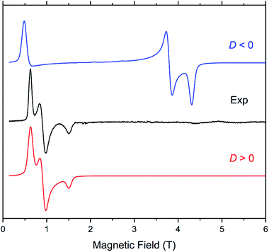
The four complexes were also investigated by HFEPR. Given the large magnitude of D as suggested by susceptibility measurements and theoretical results, HFEPR was not expected to deliver its value; rather, we hoped to determine its sign, and the rhombicity factor (E/D) of the ZFS tensor. Indeed, two samples, DCB@1 and TAN@1, both kept in (frozen) solution to avoid loss of the guest molecules, produced fine powder-patterned HFEPR spectra at low temperatures (Fig. 4 and S10–S12†). Rather than using the effective S = 1/2 spin Hamiltonian in interpreting these spectra, we used the S = 3/2 spin Hamiltonian, assuming an arbitrarily large value of D compared to the sub-THz wave frequency. HFEPR, in agreement with the NEVPT2 calculations, established a positive sign of D and delivered the values of rhombicity factor |E/D| plus the components gi of the intrinsic S = 3/2 g-tensor, shown in Table 2.
| Compound | g x | g y | g z | g x | g y | g z | E/Db |
|---|---|---|---|---|---|---|---|
| a g i values of the ground Kramer's doublet extracted from the fit of the magnetisation curves (DCB@1 and TAN@1) or the HFEPR spectra (TOL@1 and PYR@1). b g i and E/D values of the anisotropic S = 3/2 ground state from the simulation of the HFEPR spectra. | |||||||
| DCB@1 | 4.05 | 6.05 | 2.45 | 2.54 | 2.56 | 2.59 | 0.130 |
| TAN@1 | 4.06 | 6.00 | 2.48 | 2.52 | 2.56 | 2.59 | 0.125 |
| TOL@1 | 3.90 | 5.90 | 2.50 | — | — | — | ∼0.110 |
| PYR@1 | 4.09 | 6.10 | 2.52 | — | — | — | ∼0.075 |
HFEPR measurements of samples of PYR@1 and TOL@1 were not as successful, however, since the pronounced crystallinity of these samples prohibited obtaining ideal powder spectra. Still, positive values of D were confirmed in these two cases, and the rhombicity factor evaluated (Fig. S13 and S14†). The usual method of dealing with crystalline samples, i.e. grinding, was problematic due to the presence of solvent, and brought no improvement.
The dc magnetisation data in the form of the M vs. H plots (M being the magnetisation per CoII unit and H the applied dc magnetic field) for DCB@1, TAN@1, TOL@1 and PYR@1 (measured as solvent suspensions) were registered between 2 and 10 K and they are shown in Fig. S15.† Usually, the axial (D) and rhombic (E/D) ZFS parameters can be estimated from the thermal dependence of the magnetisation isotherms. Thus, the M vs. H/T plots are quite different and, when the weak magnetic couplings are ruled out, this is clear proof of the presence of non-negligible ZFS. However, when |D| is very large, at these low temperatures only the ground Kramer doublet is populated and the M vs. H/T plots superimpose which is the case for DCB@1, TAN@1, TOL@1 and PYR@1 (Fig. S16† confirms this point for PYR@1). In such a case, it is not possible to extract the ZFS parameters from magnetization curves, but they can be simulated by using the spin Hamiltonian for an effective doublet spin state
| (Seff = 1/2), H = βH(gxSx + gySy + gzSz). | (2) |
For DCB@1 and TAN@1, simulations of the magnetisation curves were done from the components of the g-factor obtained from the HFEPR experiments (Table 2), which superimpose well with the experimental data (solid line in Fig. S15a and b†). Otherwise, the fits of the magnetization curves were done through the VPMAG program48 for TOL@1 and PYR@1, where a complete HFEPR study was not possible (solid line in Fig. S15c and d†). In the last two cases, the found gi components values are in good agreement with a positive D value (Table 2). We like to stress that, from the gi and E/D values for a S = 3/2 of DCB@1 (Table 2) and through the equations proposed by Gatteschi et al.,50 it is possible to evaluate the gi components of the ground state Kramer doublet (gx = 4.08, gy = 5.98 and gz = 2.26), which perfectly matches with those found from the HFEPR spectrum (gx = 4.05, gy = 6.05 and gz = 2.45).
In conclusion, the combination of the thermal dependence of the magnetic susceptibility and the magnetization data, HFEPR spectroscopy and the theoretical study for DCB@1, TAN@1, TOL@1 and PYR@1, unambiguously confirms the large and positive axial ZFS (D > 0) with non-negligible rhombic ZFS (E/D ≈ 0.12) and also their dependence on the nature of the guest molecule, which provokes non-negligible changes in the geometry of the coordination sphere of the CoII ion.
Dynamic (ac) magnetic properties: guest-induced switching of the slow magnetic relaxation
The large and positive magnetic anisotropy values observed for the octahedral cobalt(II) ions in DCB@1, TAN@1, TOL@1 and PYR@1 together with the fact that CoII ions are very well isolated (see the structural section), strongly suggest that slow magnetic relaxation effects typical of SIMs could be observed, prompting us to study the dynamic magnetic properties of this series of compounds.Firstly, we investigated the alternating current (ac) magnetic susceptibility of the parent compound DCB@1 in the form of the χM′ and χM′′ versus T plots (χM′ and χM′′ being the in-phase and out-of-phase ac magnetic susceptibilities per mononuclear unit) at different applied static fields in the range of 0–1.0 kG (Fig. 5 and S17–19†). In a zero dc magnetic field, no χM′′ signals can be observed (Fig. S17†) even for the highest frequency used (ν = 10 kHz), suggesting that fast zero-field quantum tunnelling relaxation of the magnetization effects are present. However, when such a small static dc field as 250 G is applied, strong frequency-dependent maxima appear in both χM′ and χM′′ below 10 K (Fig. 5). Additional ac measurements for DCB@1 under higher applied dc fields of 500 and 1000 G are shown in Fig. S18 and S19,† showing the same single strong frequency-dependent χM′′ maxima below 10 K. Interestingly, no divergence in χM′′ below the blocking temperature (TB) was observed, even with such a very small applied dc field as 250 G.
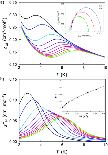 | ||
| Fig. 5 Temperature dependence of χM′ (a) and χM′′ (b) of DCB@1 in a 250 G applied static field and under a ±5.0 G oscillating field in the frequency range of 0.1–10 kHz. The insets show the Cole–Cole plots at 4.0, 5.0 and 6.0 K (a) and the Arrhenius plot (b) in the high temperature region. The solid lines are the best fit curves (see Table S3†). | ||
These results are in contrast to those found in most octahedral cobalt(II) SIMs where higher applied fields are required to observe frequency dependent signals with clear out-of-phase peaks.22 This observation strongly suggests that organising SIMs in a MOF is a good strategy to isolate them, thus minimising intermolecular interactions, which are often associated with complex magnetic relaxation processes.
Taking into account the slow magnetic relaxation effects observed for the parent compound of the series DCB@1 and, considering that the exchange of the DCB guest molecules by TAN, TOL or PYR is accompanied by non-negligible distortion of the cobalt(II) environments and tuning of the corresponding D values (see Table 1), it was easy to envisage that the guest exchange process can modify the dynamic magnetic properties of this series. Thus, alternating current (ac) magnetic susceptibility measurements were also carried out for TAN@1, TOL@1 and PYR@1.
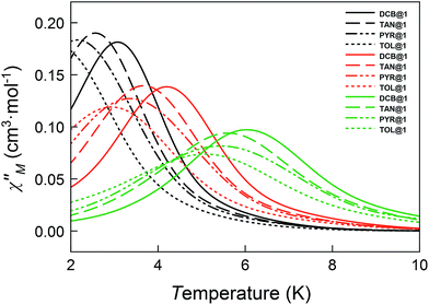
The magnetic ac measurements in a 1000 G applied static field showed frequency-dependent maxima, in both χM′ and χM′′, for the three adsorbates below 10 K (Fig. S20–S22†), which are similar to those observed for compound DCB@1. Indeed, the position of the out-of-phase (χM′′) peaks depends on the nature of the solvent molecule hosted in the porous structure, that is, the TB can be tuned by systematically varying the nature of the guest molecule (Fig. S19–S22†). This empirical observation is in the line of that predicted by the theoretical calculations and the experimental static magnetic properties and, ultimately confirms that the distortions of the metal environments caused by the exchange of the guest molecules also modify the dynamic magnetic properties of the cobalt(II) centres. Fig. 6 shows in detail the switch of the TB values at a given frequency depending on the solvent nature. In this respect, a temperature shift of up to 1.5 K is observed between DCB@1 (highest TB) and TOL@1 (lowest TB). The important distortions in the octahedral environments of cobalt(II) ions (see Fig. 1 and Table S2†), caused by the exchange of the aromatic solvent guests, lie undoubtedly at the origin of this switching behaviour, as extracted from the analysis of the combined dynamic and static magnetic properties.
The Cole–Cole plots at different temperatures and applied dc fields for DCB@1, TAN@1, TOL@1 and PYR@1 gave almost perfect semicircles which can be fitted by the generalized Debye model51 (solid lines in the insets of Fig. 5a and S18a–S22a†). The calculated low values of the α parameter at the different applied dc fields (see Table S3†) support single relaxation processes in all the cases and discard thus a spin-glass behavior52 (α = 0 for a Debye model). Yet, for all four compounds, two different relaxation processes are observed, where the relaxation times calculated from the maximum of χM′′ at a given frequency (τ = 1/2πν) follow the Arrhenius law characteristic of a thermally activated mechanism for each relaxation [τ = ((1/τ01)exp(Ea1/kBT) + (1/τ02)exp(Ea2/kBT))−1] (solid lines in the insets of Fig. 5b and S18b–S22b†). Thus, the calculated values of the first pre-exponential factor (τ0) and activation energy (Ea) (see Table S3†) are consistent with those found for previously reported octahedral cobalt(II) SIMs.22,49 However, lower values of Ea are found for the second relaxation process.
These two different processes found in all four compounds correspond to a unique CoII ion as Cole–Cole plots suggest, i.e., both processes are competing in each magnetic centre. This kind of non-linear Arrhenius plot is usually attributed to the sum of different relaxation processes that include Orbach mechanism, quantum tunnelling, direct and Raman processes. For the last two, the spin-lattice relaxation time is given for τ−1 = ATn, where n = 1 for the direct mechanism and n = 7 or 9 for the Raman process in non-Kramer or Kramer ions, respectively. But, if optical and/or acoustic phonons are also considered, n values between 1 and 6 can be also reasonable. In our cases, considering only Orbach and Raman relaxation processes is enough to correctly simulate the experimental data and, therefore, the inclusion of other relaxation processes is neither needed nor have physical meaning; however, the best fits lead to n values around 16, which is not acceptable. Even more, correct fits can also be reached with n values into the range from 1 to 55.
A possible alternative consists of verifying that the {τ,T} pair follows a power law, where a linear dependence must be observed in ln(τ) vs. ln(T) plots. In the four studied systems and at an applied magnetic field of 1.0 kG, the n values fluctuate from 2 to 4 (Table S4†). However, the experimental data in both relaxation processes – Orbach and Raman – follow the same law despite of their different nature (Fig. S23†). That is why we think global relaxation involving two different Orbach processes could be more adequate to explain the SIM behaviour of this family of compounds, but an easy explanation is not evident. Anyway, taking into account the important asymmetry between the axial and perpendicular g-factor of CoII ions, two different relaxation times (parallel and transverse) could be envisaged. On the other hand, the double Arrhenius regimes are not observed in all known CoII SIMs,53,54 which could be related to different weight of the rhombic ZFS in them. However, deeper studies are necessary to confirm or reject these possibilities in most SIMs.
Conclusions
In summary, we report a new coordination polymer (DCB@1) displaying single-ion magnetic behaviour, which has been constructed by following a rational synthetic strategy consisting of the use of a very long organic spacer that affords a two-dimensional structure and prevents any magnetic interaction between the cobalt centres. As a consequence, the resulting magnetically isolated, tetragonally distorted octahedral cobalt(II) ions, exhibit slow magnetic relaxation effects typical of SIMs. This novel porous material is able to exchange, in a post-synthetic SC to SC process, the DCB molecules hosted in its pores with other aromatic molecules (TAN, TOL, and PYR) to yield three new adsorbates (TAN@1, TOL@1 and PYR@1). These compounds also show SIM behaviour, which is dependent on the nature of the guest molecule. The exchange process, followed by single-crystal X-ray diffraction, clearly outlines a putative role of solvent guest molecules by inducing “non-innocent” distortions on the ligand conformation and, ultimately, leaving a “fingerprint” on the cobalt environments. The combined analysis of experimental (spectroscopic and magnetic properties) and theoretical (NEVPT2 calculations) data supports unambiguously that the distortions in the metal environments are responsible for this guest-dependent SIM behaviour. Overall, these results reaffirm the recent findings shown by Long et al.44 and expand the very limited scope of guest-dependent SIM-MOFs.Acknowledgements
This work was supported by the MINECO (Spain) (Projects CTQ2013-46362-P, CTQ2013-44844-P and MDM-2015-0538), the Generalitat Valenciana (Spain) (Project PROMETEOII/2014/070) and the Ministero dell’Istruzione, dell’Università e della Ricerca (Italy). J. V. thanks the MICINN (Spain) for a predoctoral contract. Thanks are also extended to the MICINN Ramón y Cajal Program (E. P.). We are especially thankful to Dr Rafael Ruiz-García (Universitat de València) for unselfish help and continuous interest in this work. The National High Magnetic Field Laboratory is funded by the NSF through a Cooperative Agreement DMR-1157490, the State of Florida and the US Department of Energy. We are grateful to Dr Andrew Ozarowski (NHMFL) for the EPR simulation and fitting software SPIN.Notes and references
- R. Sessoli, D. Gatteschi, A. Caneschi and M. A. Novak, Nature, 1993, 365, 141–143 CrossRef CAS.
- R. Sessoli, H. L. Tsai, A. R. Schake, S. Wang, J. B. Vincent, K. Folting, D. Gatteschi, G. Christou and D. N. Hendrickson, J. Am. Chem. Soc., 1993, 115, 1804–1816 CrossRef CAS.
- L. Bogani and W. Wernsdorfer, Nat. Mater., 2008, 7, 179–186 CrossRef CAS PubMed.
- S. Sanvito, Chem. Soc. Rev., 2011, 40, 3336–3355 RSC.
- O. Kahn, Molecular Magnetism, VCH Publishers, New York, 1993 Search PubMed.
- D. Maspoch, D. Ruiz-Molina and J. Veciana, Chem. Soc. Rev., 2007, 36, 770–818 RSC.
- P. Dechambenoit and J. R. Long, Chem. Soc. Rev., 2011, 40, 3249–3265 RSC.
- T. Grancha, J. Ferrando-Soria, M. Castellano, M. Julve, J. Pasán, D. Armentano and E. Pardo, Chem. Commun., 2014, 50, 7569–7585 RSC.
- N. Ishikawa, M. Sugita, T. Ishikawa, S.-Y. Koshihara and Y. Kaizu, J. Am. Chem. Soc., 2003, 125, 8694–8695 CrossRef CAS PubMed.
- N. Ishikawa, M. Sugita, T. Ishikawa, S. Koshihara and Y. Kaizu, J. Phys. Chem. B, 2004, 108, 11265–11271 CrossRef CAS.
- N. Ishikawa, M. Sugita and W. Wernsdorfer, J. Am. Chem. Soc., 2005, 127, 3650–3651 CrossRef CAS PubMed.
- A. Yamashita, A. Watanabe, S. Akine, T. Nabeshima, M. Nakano, T. Yamamura and T. Kajiwara, Angew. Chem., 2011, 123, 4102–4105 CrossRef.
- P. Zhang, L. Zhang, C. Wang, S. Xue, S.-Y. Lin and J. Tang, J. Am. Chem. Soc., 2014, 136, 4484–4487 CrossRef CAS PubMed.
- J. D. Rinehart and J. R. Long, J. Am. Chem. Soc., 2009, 131, 12558–12559 CrossRef CAS PubMed.
- J. D. Rinehart, K. R. Meihaus and J. R. Long, J. Am. Chem. Soc., 2010, 132, 7572–7573 CrossRef CAS PubMed.
- V. Mougel, L. Chatelain, J. Pécaut, R. Caciuffo, E. Colineau, J.-C. Griveau and M. Mazzanti, Nat. Chem., 2012, 4, 1011–1017 CrossRef CAS PubMed.
- N. Magnani, E. Colineau, J.-C. Griveau, C. Apostolidis, O. Walter and R. Caciuffo, Chem. Commun., 2014, 50, 8171–8173 RSC.
- W. H. Harman, T. D. Harris, D. E. Freedman, H. Fong, A. Chang, J. D. Rinehart, A. Ozarowski, M. T. Sougrati, F. Grandjean, G. J. Long, J. R. Long and C. J. Chang, J. Am. Chem. Soc., 2010, 132, 18115–18126 CrossRef CAS PubMed.
- D. E. Freedman, W. H. Harman, T. D. Harris, G. J. Long, C. J. Chang and J. R. Long, J. Am. Chem. Soc., 2010, 132, 1224–1225 CrossRef CAS PubMed.
- T. Jurca, A. Farghal, P. Lin, I. Korobkov, M. Murugesu and D. S. Richeson, J. Am. Chem. Soc., 2011, 133, 15814–15817 CrossRef CAS PubMed.
- J. M. Zadrozny and J. R. Long, J. Am. Chem. Soc., 2011, 133, 20732–20734 CrossRef CAS PubMed.
- J. Vallejo, I. Castro, R. Ruiz-García, J. Cano, M. Julve, F. Lloret, G. de Munno, W. Wernsdorfer and E. Pardo, J. Am. Chem. Soc., 2012, 134, 15704–15707 CrossRef CAS PubMed.
- J. M. Zadrozny, M. Atanasov, A. M. Bryan, C.-Y. Lin, B. D. Rekken, P. P. Power, F. Neese and J. R. Long, Chem. Sci., 2013, 4, 125 RSC.
- J. Vallejo, A. Pascual-Álvarez, J. Cano, I. Castro, M. Julve, F. Lloret, J. Krzystek, G. de Munno, D. Armentano, W. Wernsdorfer, R. Ruiz-García and E. Pardo, Angew. Chem., Int. Ed., 2013, 52, 14075–14079 CrossRef CAS PubMed.
- L. Chen, J. Wang, J.-M. Wei, W. Wernsdorfer, X.-T. Chen, Y.-Q. Zhang, Y. Song and Z.-L. Xue, J. Am. Chem. Soc., 2014, 136, 12213–12216 CrossRef CAS PubMed.
- J. Martínez-Lillo, T. F. Mastropietro, E. Lhotel, C. Paulsen, J. Cano, G. de Munno, J. Faus, F. Lloret, M. Julve, S. Nellutla and J. Krzystek, J. Am. Chem. Soc., 2013, 135, 13737–13748 CrossRef PubMed.
- D. Bradshaw, J. B. Claridge, E. J. Cussen, T. J. Prior and M. J. Rosseinsky, Acc. Chem. Res., 2005, 38, 273–282 CrossRef PubMed.
- G. Férey, Chem. Soc. Rev., 2008, 37, 191–214 RSC.
- C. Janiak, Dalton Trans., 2003, 2781–2804 RSC.
- S. Kitagawa and R. Matsuda, Coord. Chem. Rev., 2007, 251, 2490–2509 CrossRef CAS.
- J. R. Long and O. M. Yaghi, Chem. Soc. Rev., 2009, 38, 1213–1214 RSC.
- N. L. Rosi, M. Eddaoudi, J. Kim, M. O'Keeffe and O. M. Yaghi, CrystEngComm, 2002, 4, 401–404 RSC.
- G. J. Halder, C. J. Kepert, B. Moubaraki, K. S. Murray and J. D. Cashion, Science, 2002, 298, 1762–1765 CrossRef CAS PubMed.
- G. Agusti, R. Ohtani, K. Yoneda, A. B. Gaspar, M. Ohba, J. F. Sánchez-Royo, M. C. Muñoz, S. Kitagawa and J. A. Real, Angew. Chem., Int. Ed., 2009, 48, 8944–8947 CrossRef CAS PubMed.
- M. Ohba, K. Yoneda, G. Agusti, M. C. Muñoz, A. B. Gaspar, J. A. Real, M. Yamasaki, H. Ando, Y. Nakao, S. Sakaki and S. Kitagawa, Angew. Chem., Int. Ed., 2009, 48, 4767–4771 CrossRef CAS PubMed.
- O. M. Yaghi, M. O'Keeffe, N. W. Ockwig, H. K. Chae, M. Eddaoudi and J. Kim, Nature, 2003, 423, 705–714 CrossRef CAS PubMed.
- J.-R. Li, R. J. Kuppler and H.-C. Zhou, Chem. Soc. Rev., 2009, 38, 1477–1504 RSC.
- J. Ferrando-Soria, H. Khajavi, P. Serra-Crespo, J. Gascon, F. Kapteijn, M. Julve, F. Lloret, J. Pasán, C. Ruiz-Pérez, Y. Journaux and E. Pardo, Adv. Mater., 2012, 24, 5625–5629 CrossRef CAS PubMed.
- J. J. Baldoví, E. Coronado, A. Gaita-Ariño, C. Gamer, M. Giménez-Marqués and G. Mínguez Espallargas, Chem.–Eur. J., 2014, 20, 10695–10702 CrossRef PubMed.
- N. R. Champness, A. N. Khlobystov, A. G. Majuga, M. Schröder and N. V. Zyk, Tetrahedron Lett., 1999, 40, 5413–5416 CrossRef CAS.
- A. E. Ion, S. Nica, A. M. Madalan, S. Shova, J. Vallejo, M. Julve, F. Lloret and M. Andruh, Inorg. Chem., 2015, 54, 16–18 CrossRef CAS PubMed.
- J. Palion-Gazda, T. Klemens, B. Machura, J. Vallejo, F. Lloret and M. Julve, Dalton Trans., 2015, 44, 2989–2992 RSC.
- X. Liu, L. Sun, H. Zhou, P. Cen, X. Jin, G. Xie, S. Chen and Q. Hu, Inorg. Chem., 2015, 54, 8884–8886 CrossRef CAS PubMed.
- X. Zhang, V. Vieru, X. Feng, J.-L. Liu, Z. Zhang, B. Na, W. Shi, B.-W. Wang, A. K. Powell, L. F. Chibotaru, S. Gao, P. Cheng and J. R. Long, Angew. Chem., Int. Ed., 2015, 54, 9861–9865 CrossRef CAS PubMed.
- J. A. Real, E. Andrés, M. C. Muñoz, M. Julve, T. Granier, A. Bousseksou and F. Varret, Science, 1995, 268, 265–267 CAS.
- N. Moliner, M. C. Muñoz, S. Letard, X. Solans, N. Menendez, A. Goujon, F. Varret and J. A. Real, Inorg. Chem., 2000, 39, 5390–5393 CrossRef CAS PubMed.
- F. Lloret, M. Julve, J. Cano, R. Ruiz-García and E. Pardo, Inorg. Chim. Acta, 2008, 361, 3432–3445 CrossRef CAS.
- J. Cano, VPMAG package, University of Valencia, Valencia, Spain, 2003 Search PubMed.
- E. Colacio, J. Ruiz, E. Ruiz, E. Cremades, J. Krzystek, S. Carretta, J. Cano, T. Guidi, W. Wernsdorfer and E. K. Brechin, Angew. Chem., Int. Ed., 2013, 52, 9130–9134 CrossRef CAS PubMed.
- L. Banci, A. Bencini, C. Benelli, D. Gatteschi and C. Zanchini, Struct. Bonding, 1982, 52, 37 CrossRef CAS.
- R. H. Cole and K. S. Cole, J. Chem. Soc., 1941, 9, 341 Search PubMed.
- J. A. Mydosh, Spin Glasses: An Experimental Introduction, Taylor & Francis, London, 1993 Search PubMed.
- F. Yang, Q. Zhou, Y. Zhang, G. Zeng, G. Li, Z. Shi, B. Wang and S. Feng, Chem. Commun., 2013, 49, 5289–5291 RSC.
- D. Wu, X. Zhang, P. Huang, W. Huang, M. Ruan and Z. W. Ouyang, Inorg. Chem., 2013, 52, 10976 CrossRef CAS PubMed.
Footnote |
| † Electronic supplementary information (ESI) available: Preparation and physical characterization data. Crystallographic refinement details. Additional figures (Fig. S1–S23) and tables (Tables S1–S4). CCDC 1415915–1415921. For ESI and crystallographic data in CIF or other electronic format see DOI: 10.1039/c5sc04461h |
| This journal is © The Royal Society of Chemistry 2016 |

