Rational synthesis of metal–organic framework composites, hollow structures and their derived porous mixed metal oxide hollow structures†
Daoping
Cai
,
Bin
Liu
,
Dandan
Wang
,
Lingling
Wang
,
Yuan
Liu
,
Baihua
Qu
,
Xiaochuan
Duan
,
Qiuhong
Li
* and
Taihong
Wang
*
Pen-Tung Sah Institute of Micro-Nano Science and Technology, Xiamen University, Xiamen 361000, China. E-mail: liqiuhong2004@hotmail.com; thwang@xmu.edu.cn; Fax: +86-0592-2197196; Tel: +86-0592-2183063
First published on 17th November 2015
Abstract
Metal–organic frameworks (MOFs) have attracted considerable attention for their important applications. Recently, significant efforts have been devoted to constructing hollow MOF structures and integrating MOFs with other functional materials to further enhance the inherent performance and endow them with new functions. However, it still remains a big challenge to synthesize well-defined MOF composites and MOF hollow structures, especially those with structural and compositional complexity. In this work, we demonstrate a chemical transformation method to synthesize unique MOF composites, as well as hollow and complex hollow MOF structures. This method could intelligently overcome the difficulty that is caused by the possible lattice mismatch between MOFs and other functional materials. Impressively, a series of unique MOF@MOF core–shell structures, MOF composites, MOF hollow and complex hollow structures are successfully synthesized. Moreover, porous mixed metal oxide hollow and complex structures are obtained by annealing the corresponding MOF hollow and complex hollow structures in air. We anticipate that these unique MOF composites, hollow structures and the derived porous mixed metal oxide hollow structures could find promising applications in many other fields. As an example, NiFe oxide cube-in-box complex hollow nanostructures are evaluated as anode materials for lithium-ion batteries (LIBs), which exhibit enhanced electrochemical performance compared to the simple nanobox counterparts.
1. Introduction
Metal organic frameworks (MOFs) or coordination polymers, which consist of metal ions linked together by organic bridging ligands, are a new class of crystalline materials that have a well-defined pore structure, large surface area and easily tailorable chemistry.1–3 Because of their attractive properties, MOFs have demonstrated great potential in a variety of important applications such as gas storage, adsorptive separation, drug delivery, catalysis, sensors, and so on.4–9 Consequently, great efforts have been devoted to the rational synthesis of MOFs and great success has been achieved. Despite these advances, constructing nanosized hollow MOFs still remains a big challenge and only a few reports have been published so far.10–17 Hollow micro-/nanostructures, especially those with complex structures in terms of their structure and composition, are expected to achieve optimized physical/chemical properties for specific applications.18–20 Template methods are the most straightforward methods for constructing hollow MOF structures. Several hollow MOF structures have been synthesized using surface-modified polystyrene (PS) spheres as hard templates and emulsion droplets as soft templates.13–15 Template-free approaches such as Ostwald ripening and spray-drying strategies are also developed to synthesize hollow MOF structures.16,17 However, the above two methods for the synthesis of hollow MOF structures suffer from several problems. One is that the as-prepared hollow MOF structures usually possess a simple spherical shape with a single shell. Another problem is that the resulting hollow MOF structures are very large and their size distribution is broad. Particularly, the crystallinity of these hollow MOF structures decreases seriously during the formation process. Without good crystallinity, the attractive properties of MOFs will not be available. Recently, Yamauchi et al. demonstrated a chemical etching method to synthesize nanosized Prussian blue (PB) with hollow interiors and good crystallinity.21 However, this chemical etching method is dangerous because the –CN group may be converted to the toxic HCN gas in hot acidic solution. Besides, time-dependent experiments indicated that the hollow PB structures could be destroyed or even totally dissolved on slightly prolonging the reaction time. Based on the above considerations, it is highly desirable yet challenging to develop facile and efficient methods to synthesize hollow MOF structures, especially those with complex interiors and uniform size, as well as good crystallinity.Recently, there has been growing interest in integrating MOFs with other functional materials (such as metals, semiconductors, carbon and so on) to obtain composite materials, which is considered to be a useful approach to further extend the potential applications of MOFs.22–27 Compared with pure MOFs, MOF composites can exhibit improved performance or new behaviors due to their synergistic effect. Generally, MOF composites can be synthesized either by using MOFs as templates to generate nanoparticles embedded into their cavities or by encapsulating presynthesized nanoparticles in MOFs to form core–shell MOF composites.28 Embedding-type MOF composites have been extensively studied, in which small metal (e.g., Au, Pd, Pt, etc.) and semiconductor (e.g., ZnO and GaN) nanoparticles are embedded into the cavities or channels of MOFs.29,30 However, control of the size, composition, dispersive nature and spatial distribution of the embedded nanoparticles within MOF matrices is challenging.28 In addition, some of the local framework structure may be damaged during particle formation, and some particles could undesirably form on the external surface of the MOF crystals.23 In this regard, the synthesis of core–shell MOF composites seems attractive. For example, Kuang et al. demonstrated a self-template strategy to synthesize ZnO@zeolitic-imidazolate-framework-8 (ZIF-8) core–shell nanostructures, which exhibited a selective photoelectrochemical response toward different hole scavengers due to the presence of ZIF-8.31 The major difficulty in the synthesis of these kinds of MOF composites lies in confining the growth of MOFs to the core surface. As we know, crystalline MOFs prefer self-nucleation in solution due to the possible lattice mismatch between the MOF and other functional materials. It is worth mentioning that the metal@MOF core–shell composites are well-studied, but the synthesis of well-defined semiconductor@MOF core–shell composites is still at an early stage.31–33 Moreover, the present core–shell MOF composites are mostly solid core–shell nanostructures, while other distinctive nanostructures such as yolk–shelled or multi-shelled hollow nanostructures have rarely been reported. Based on the above discussion, significant attention should be devoted to extending the types and arrangements of the nanoparticle core and MOF shell.
As a class of crystalline MOFs, PB and its analogues (PBAs) with the formula of MII3[MIII(CN)6]2·nH2O (M = Fe, Mn, Ni, Co, Zn, etc.) can be easily obtained at room temperature in water–ethanol systems. The as-synthesized PBAs possess uniform sizes, diverse compositions and various morphologies.21,34,35 Furthermore, PBAs with heterogeneous structures could be easily obtained by epitaxial deposition since the crystal structures and lattice constants of most PBAs are close to each other.36–38 In this work, we first demonstrate a chemical transformation method to synthesize unique MOF composites, as well as hollow and complex hollow MOF structures. This chemical transformation method is based on the different chemical stabilities of FeFe PB and NiFe PBA in alkaline solution, which is quite different from the previous methods for preparing MOF composites and hollow MOF nanostructures. Through step-by-step MOF growth and subsequent transformation processes, a series of unique MOF@MOF core–shell structures, MOF composites, MOF hollow and complex hollow structures are successfully synthesized. Besides, MOFs have been considered as novel templates or precursors to construct porous nanoarchitectures with intriguing properties.39–44 For example, MOF-derived ZnO@ZnO quantum dots/C composites exhibited excellent performance for lithium ion batteries;39 MOF-derived mesoporous molybdenum carbide displayed remarkable electrocatalytic performance for hydrogen production.40 In this work, the as-synthesized NiFe PBA nanoboxes and cube-in-box hollow nanostructures are successfully converted to NiFe oxide nanoboxes and cube-in-box hollow nanostructures without obvious aggregation and structure cracking by a thermal annealing in air. When evaluated as anode materials, the NiFe oxide with cube-in-box complex hollow nanostructures display enhanced electrochemical performance compared to the simple nanobox counterparts.
2. Experimental section
2.1. Materials preparation
All of the reagents were of analytical purity grade and used without further purification.2.2. Materials characterization
Powder X-ray diffraction (XRD) patterns of the as-prepared products were recorded using an X-ray diffractometer (Rigaku Ultima IV) with Cu Kα irradiation. The morphology and crystal structure of the as-prepared products were examined by field-emission scanning electron microscopy (SEM, ZEISS SUPRA 55) and transmission electron microscopy (TEM, JEOL JEM 2100) with an acceleration voltage of 200 kV.2.3. Electrochemical measurements
The electrochemical test was characterized using CR2016-type coin cells. Pure lithium foils were used as counter and reference electrodes. The active materials were mixed with carbon black and carboxyl methyl cellulose in a weight ratio of 70![[thin space (1/6-em)]](https://www.rsc.org/images/entities/char_2009.gif) :
:![[thin space (1/6-em)]](https://www.rsc.org/images/entities/char_2009.gif) 20
20![[thin space (1/6-em)]](https://www.rsc.org/images/entities/char_2009.gif) :
:![[thin space (1/6-em)]](https://www.rsc.org/images/entities/char_2009.gif) 10, which were dispersed in distilled water and absolute alcohol with constant stirring for 8 h to form a homogeneous slurry. The well-mixed slurry was then spread onto a copper foil and dried at 100 °C in a vacuum oven for 12 h. The diameter of the electrode was 12 mm, and the density of the active material was about 0.6–0.8 mg cm−2. The electrolyte solution was 1 M LiPF6 in ethylene carbonate–dimethyl carbonate–diethyl carbonate (1
10, which were dispersed in distilled water and absolute alcohol with constant stirring for 8 h to form a homogeneous slurry. The well-mixed slurry was then spread onto a copper foil and dried at 100 °C in a vacuum oven for 12 h. The diameter of the electrode was 12 mm, and the density of the active material was about 0.6–0.8 mg cm−2. The electrolyte solution was 1 M LiPF6 in ethylene carbonate–dimethyl carbonate–diethyl carbonate (1![[thin space (1/6-em)]](https://www.rsc.org/images/entities/char_2009.gif) :
:![[thin space (1/6-em)]](https://www.rsc.org/images/entities/char_2009.gif) 1
1![[thin space (1/6-em)]](https://www.rsc.org/images/entities/char_2009.gif) :
:![[thin space (1/6-em)]](https://www.rsc.org/images/entities/char_2009.gif) 1, in weight percent). A Celgard 2400 microporous polypropylene membrane was used as a separator. The coin-type cells were assembled in an argon-filled glovebox with water and oxygen contents less than 1 ppm, and then the cells were measured with a Land CT 2001 battery tester.
1, in weight percent). A Celgard 2400 microporous polypropylene membrane was used as a separator. The coin-type cells were assembled in an argon-filled glovebox with water and oxygen contents less than 1 ppm, and then the cells were measured with a Land CT 2001 battery tester.
3. Results and discussion
As the first example, the chemical transformation method for the synthesis of the box-in-box Fe(OH)3@NiFe PBA composites and hollow NiFe PBA nanoboxes is illustrated in Fig. 1. First, the FeFe(Fe4[Fe(CN)6]3·xH2O) particles are synthesized as the seeds. Second, a layer of NiFe PBA is deposited onto the FeFe PB seeds through epitaxial deposition, forming core–shell FeFe@NiFe PBA nanocubes. After that, the FeFe@NiFe PBA nanocubes are subjected to reaction with a dilute NaOH solution at room temperature. FeFe PB is unstable in alkaline solution and undergoes an ion exchange reaction with hydroxide ions to form insoluble Fe(OH)3, giving rise to box-in-box Fe(OH)3@NiFe PBA composites.19 Furthermore, the inner Fe(OH)3 can be removed by washing with HCl at room temperature to obtain the hollow NiFe PBA nanoboxes. | ||
| Fig. 1 Schematic illustration of the synthesis of the box-in-box Fe(OH)3@NiFe PBA composites and NiFe PBA nanoboxes. | ||
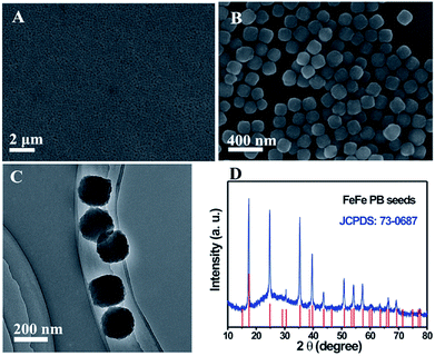
Fig. 2A and B show the low and high-magnification SEM images of the as-prepared FeFe PB seeds. The FeFe PB nanoparticles are highly uniform with an average size of approximately 180 nm. The TEM image indicates that these FeFe PB nanoparticles show a dense solid texture without discernible porosity (Fig. 2C). The phase purity and crystallographic structure of FeFe PB were examined by powder X-ray diffraction (XRD), as shown in Fig. 2D. The strong peaks reveal the good crystallinity of the FeFe PB nanoparticles, and all of the diffraction peaks could be indexed to fcc Fe4[Fe(CN)6]3 (JCPDS: 73-0687). No additional peaks are detected, revealing the high purity of the product. Energy-dispersive X-ray spectroscopy (EDX) analysis indicates that the sample is mainly composed of Fe, C and N elements. Thanks to their similar crystal structure and lattice constant, a layer of NiFe PBA can be easily deposited onto the FeFe PB seeds through epitaxial deposition at room temperature. The average size of the FeFe@NiFe PBA nanocubes increases to about 270 nm, and the surface of these FeFe@NiFe PBA nanocubes becomes smooth (Fig. 3A). TEM image observation further confirms the formation of a core–shell structure through the difference in contrast between the outer and inner parts (Fig. 3D and G). The XRD pattern of the core–shell FeFe@NiFe PBA nanocubes is shown in Fig. S1.† The diffraction peaks shift slightly to the left, which is ascribed to the newly formed NiFe PBA outer layer. It can be concluded that the diffraction peaks come from both FeFe PB (JCPDS: 73-0687) and NiFe PBA (JCPDS: 86-0501). Elemental analysis confirms that both the metals Ni and Fe are present in the core–shell FeFe@NiFe PBA nanocubes (Fig. S2†). After reacting with dilute NaOH solution, it can be seen that the core–shell particles are converted to hollow-based structures with Fe(OH)3 inside (Fig. 3B). TEM images can clearly reveal the formation of the box-in-box Fe(OH)3@NiFe PBA structures (Fig. 3E and H). It should be noted that the inner Fe(OH)3 possesses hollow and amorphous features (Fig. S1†). The inner Fe(OH)3 can be removed via washing with HCl to obtain the hollow NiFe PBA nanoboxes. Fig. 3C, F and I show the SEM and TEM images of the hollow NiFe PBA nanoboxes. It can be seen that the inner Fe(OH)3 is completely removed after washing with HCl. The shell thickness of the hollow NiFe PBA nanoboxes is around 45 nm. In the XRD pattern of the hollow NiFe PBA nanoboxes, all the diffraction peaks can be indexed to NiFe PBA (JCPDS: 86-0501) (Fig. S3†). The strong peaks reveal the good crystallinity of the hollow NiFe PBA nanoboxes. Based on the above results, hollow NiFe PBA nanoboxes with uniform size and good crystallinity are successfully synthesized through the facile chemical transformation method.
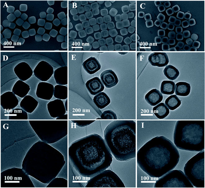 | ||
| Fig. 3 (A–C) SEM, (D–F) TEM, and (G–I) high-magnification TEM images of the FeFe@NiFe PBA nanocubes, Fe(OH)3@NiFe PBA composites and hollow NiFe PBA nanoboxes, respectively. | ||
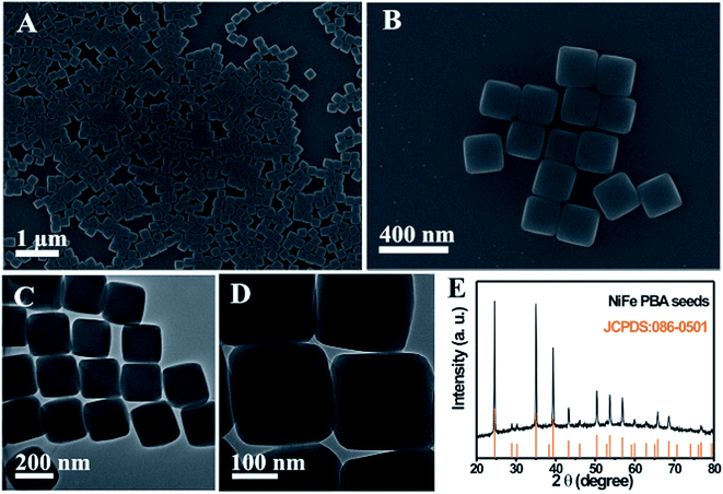
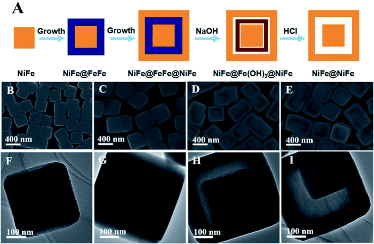
In addition, this chemical transformation method can be applied to synthesize NiFe PBA complex hollow structures. When using NiFe PBA nanocubes as the starting seeds, NiFe PBA cube-in-box complex hollow structures are obtained. The NiFe PBA nanocube seeds are synthesized through a precipitation method at room temperature. Fig. 4A and B show the SEM images of the NiFe PBA nanocubes, which are highly uniform with an average size of approximately 220 nm. These NiFe PBA nanocubes possess a very smooth surface over the particles. The TEM observations clearly reveal that NiFe PBA nanocubes are well crystallized without discernible porosity (Fig. 4C and D). The corresponding XRD pattern suggests that these NiFe PBA nanocubes are well crystallized (Fig. 4E). All the diffraction peaks are well assigned to NiFe PBA (JCPDS: 86-0501). The synthesis process of the NiFe PBA cube-in-box complex hollow structures is illustrated in Fig. 5A. Starting from the NiFe nanocubes as seeds, a layer of FeFe PB is then deposited to obtain core–shell NiFe@FeFe PBA nanocubes. By further using these “NiFe@FeFe PBA” nanocubes as seeds, another layer of NiFe PBA is then deposited to form NiFe@FeFe@NiFe PBA nanocubes. At last, NiFe PBA cube-in-box complex hollow structures are obtained by chemical transformation of the interlayer FeFe PB to Fe(OH)3 and finally removed by washing with HCl.
Fig. 5B and C show SEM images of the core–shell NiFe@FeFe PBA and NiFe@FeFe@NiFe PBA nanocubes. The average size of the core–shell NiFe@FeFe PBA and NiFe@FeFe@NiFe PBA nanocubes is about 350 and 480 nm, respectively. TEM observations can reveal the core–shell heterostructures through the difference in contrast, as shown in Fig. 5F and G. In addition, XRD measurements were also conducted to examine their core–shell structures. The XRD patterns of the core–shell NiFe@FeFe PBA and NiFe@FeFe@NiFe PBA nanocubes are shown in Fig. S4.† It can be seen that the diffraction peaks shift slightly to the right after deposition of the FeFe PB layer. After the growth of another layer of NiFe PBA, the diffraction peaks shift slightly towards the left, but not as left as the starting NiFe PBA seeds. Therefore, it can be concluded that the diffraction peaks in the XRD patterns are from both FeFe PB (JCPDS: 73-0687) and NiFe PBA (JCPDS: 86-0501). The solid NiFe@FeFe@NiFe PBA nanocubes become hollow after chemical transformation of the interlayer FeFe PB to Fe(OH)3 (Fig. 5D). TEM observation reveals that unique NiFe@Fe(OH)3@void@NiFe PBA composites with complex hollow structures are obtained (Fig. 5G). After removing Fe(OH)3, NiFe PBA cube-in-box complex hollow structures are obtained, as shown in Fig. 5E and I. The XRD pattern confirms that the obtained NiFe PBA cube-in-box complex hollow structures possess good crystallinity (Fig. S4†). All the diffraction peaks are well assigned to NiFe PBA (JCPDS: 86-0501).
According to the previous literature, FeFe PB can even react with hydroxide ions from the hydrolysis of a conjugate base under optimized conditions. Therefore, the composition of the MOF composites can be further extended by replacing NaOH with the conjugate base of a metal/metalloid oxide based weak acid.19 Taking Na2SnO3 as an example, FeFe PB could be converted to Fe(OH)3 and SnO2·xH2O in the presence of Na2SnO3 solution. By this way, SnO2·xH2O is introduced into the MOF composites to improve compositional complexity, as illustrated in Fig. 6A. Fig. 6B and C show the SEM images of the obtained NiFe@Fe(OH)3/SnO2·xH2O composites via the reaction between core–shell NiFe@FeFe PBA nanocubes and Na2SnO3 solution. The product also consists of numerous nanocubes with good uniformity. The difference in contrast between the outer and inner parts can be observed from the high-magnification SEM image, which is distinctly different from that of the starting core–shell NiFe@FeFe PBA nanocubes. It should be noted that the inner NiFe PBA nanocubes are completely encapsulated in the outer Fe(OH)3/SnO2·xH2O shell. EDX analysis indicates the presence of the metals Sn, Fe and Ni. As shown in Fig. S5,† Sn is distributed in the shell, Ni is distributed in the core, while Fe is detected in both core and shell. The core–shell structure is also clearly distinguished from the TEM observations, as shown in Fig. 6D and E. The average size of the core–shell NiFe@Fe(OH)3/SnO2·xH2O nanocubes is about 350 nm. The high-magnification TEM image reveals that the outer Fe(OH)3/SnO2·xH2O shell is porous, which consists of numerous small nanoparticles.
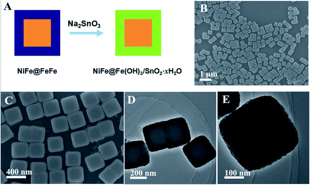 | ||
| Fig. 6 (A) Schematic illustration for the synthesis of the NiFe@Fe(OH)3/SnO2·xH2O composites; (B and C) SEM and (D and E) TEM images of the NiFe@Fe(OH)3/SnO2·xH2O composites. | ||
Recently, porous metal oxides derived from MOFs via thermal annealing have been found to exhibit intriguing properties in various important applications. In this regard, the above as-synthesized NiFe PBA nanoboxes and cube-in-box complex hollow structures are used as precursors to generate porous metal oxides by a simple thermal annealing in air. Fig. 7A and B show the typical SEM images of the NiFe oxide nanoboxes after thermal annealing of the NiFe PBA nanoboxes in air. The as-obtained NiFe oxide nanoboxes still possess uniform size without obvious aggregation and structure cracking. The XRD patterns provide further crystallinity and phase information for the product after thermal annealing. All the diffraction peaks in the XRD patterns can be assigned to the Fe2O3 (JCPDS: 39-1346) and NiO (JCPDS: 47-1049) phases (Fig. S6†). EDX analysis shows that the product mainly consists of Fe, Ni, and O where the molar ratio of Ni to Fe is 3![[thin space (1/6-em)]](https://www.rsc.org/images/entities/char_2009.gif) :
:![[thin space (1/6-em)]](https://www.rsc.org/images/entities/char_2009.gif) 2, suggesting the presence of 75% NiO and 25% Fe2O3 in the product (Fig. S7†). TEM images further confirm the well-defined hollow nanobox nanostructures (Fig. 7C and D). The size of the NiFe oxide nanoboxes is decreased to about 170 nm. The surface of the NiFe oxide nanoboxes becomes rough, which consists of small nanocrystals throughout the shell. The lattice fringes from the Fe2O3 and NiO phases can be seen in the high-resolution TEM (HRTEM) image, in which the fringe spacing of 0.25 nm can be assigned to the (311) plane of the Fe2O3 phase and that of 0.21 nm can be assigned to the (200) plane of the NiO phase (Fig. 7E and F). The corresponding selected area electron diffraction (SAED) pattern (Fig. 7G) with a series of concentric rings reveals the polycrystalline characteristics of the NiFe oxide nanoboxes. The diffraction rings can be readily indexed to the (220) and (311) planes of Fe2O3, and (111), (200) and (220) planes of the NiO phase, which is consistent with the XRD result. Fig. 7H and I show the typical SEM images of the NiFe oxide cube-in-box complex hollow structures by thermal annealing of the NiFe PBA cube-in-box complex hollow structures in air. SEM images show that the product also well maintains the morphology of the starting precursor after annealing in air. The high-magnification SEM image and TEM observation indicate that the as-synthesized NiFe oxide possesses the unique cube-in-box hollow structure, in which an obvious gap between the inner cube and outer shell can be clearly observed (Fig. 7J). The size of the outer NiFe oxide nanoboxes is about 330 nm and the size of the inner cube is about 130 nm. In the XRD pattern, the diffraction peaks of the NiFe oxide cube-in-box hollow structures are similar to those of NiFe oxide nanoboxes, which suggests that they are also composed of Fe2O3 and NiO phases (Fig. S6†).
2, suggesting the presence of 75% NiO and 25% Fe2O3 in the product (Fig. S7†). TEM images further confirm the well-defined hollow nanobox nanostructures (Fig. 7C and D). The size of the NiFe oxide nanoboxes is decreased to about 170 nm. The surface of the NiFe oxide nanoboxes becomes rough, which consists of small nanocrystals throughout the shell. The lattice fringes from the Fe2O3 and NiO phases can be seen in the high-resolution TEM (HRTEM) image, in which the fringe spacing of 0.25 nm can be assigned to the (311) plane of the Fe2O3 phase and that of 0.21 nm can be assigned to the (200) plane of the NiO phase (Fig. 7E and F). The corresponding selected area electron diffraction (SAED) pattern (Fig. 7G) with a series of concentric rings reveals the polycrystalline characteristics of the NiFe oxide nanoboxes. The diffraction rings can be readily indexed to the (220) and (311) planes of Fe2O3, and (111), (200) and (220) planes of the NiO phase, which is consistent with the XRD result. Fig. 7H and I show the typical SEM images of the NiFe oxide cube-in-box complex hollow structures by thermal annealing of the NiFe PBA cube-in-box complex hollow structures in air. SEM images show that the product also well maintains the morphology of the starting precursor after annealing in air. The high-magnification SEM image and TEM observation indicate that the as-synthesized NiFe oxide possesses the unique cube-in-box hollow structure, in which an obvious gap between the inner cube and outer shell can be clearly observed (Fig. 7J). The size of the outer NiFe oxide nanoboxes is about 330 nm and the size of the inner cube is about 130 nm. In the XRD pattern, the diffraction peaks of the NiFe oxide cube-in-box hollow structures are similar to those of NiFe oxide nanoboxes, which suggests that they are also composed of Fe2O3 and NiO phases (Fig. S6†).
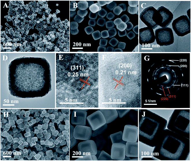 | ||
| Fig. 7 (A and B) SEM, (C and D) TEM, (E and F) HRTEM images and (G) SAED pattern of the NiFe oxide nanoboxes; (H and I) SEM and (J) TEM images of the NiFe oxide cube-in-box hollow structures. | ||
Mixed metal oxides with complex hollow structures have been regarded as a promising class of electrode materials for high-performance lithium-ion batteries (LIBs).18,45–48 In this work, the as-prepared NiFe oxide nanoboxes and cube-in-box complex hollow structures were then investigated as anode materials for LIBs. Fig. 8A and B show the typical discharge and charge curves of the NiFe oxide nanoboxes and cube-in-box complex hollow structures for the 1st, 2nd and 10th cycles at a current density of 200 mA g−1 in the range of 0.01–3.0 V (vs. Li+/Li). In the first discharge cycle, a long flat potential plateau at about 0.7 V is observed, which corresponds to the reduction of Ni2+ and Fe3+ to metallic Ni and Fe, as well as the formation of a solid electrolyte interface (SEI) film.43,48–50 Consistent with the previous reports, this plateau shifts upward close to a higher voltage of 1.0 V and becomes steeper in the subsequent discharge process, which suggests that the reduction mechanism is different from that in the first cycle. The first three CV curves of the NiFe oxide hollow boxes at a scan rate of 0.2 mV s−1 are shown in Fig. S8,† which is consistent with the previous results.48–50 During the anodic process, the peaks at 1.66 and 2.35 V correspond to the reversible oxidation of Ni to Ni2+ and Fe to Fe3+. The first discharge and charge capacities of the NiFe oxide cube-in-box complex hollow structures are 1226.8 and 1039.9 mA h g−1, corresponding to a coulombic efficiency of 84.8%. Meanwhile, the first discharge and charge capacities for the NiFe oxide nanobox are 1121.5 and 964.0 mA h g−1, corresponding to a coulombic efficiency of 86.0%. The large irreversible capacity loss in the first cycle is possibly attributed to the formation of a SEI layer and the incomplete extraction of lithium from the active material.34,39
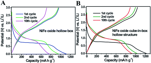 | ||
| Fig. 8 Typical discharge and charge curves of the (A) NiFe oxide nanoboxes and (B) cube-in-box complex hollow structures for the 1st, 2nd and 10th cycles at a current density of 200 mA g−1. | ||
The cycle performance of the NiFe oxide nanoboxes and cube-in-box complex hollow structures at a current density of 200 mA g−1 for 300 cycles is shown in Fig. 9. It is observed that the NiFe oxide nanoboxes and cube-in-box complex hollow structures display a similar cycling behavior. Despite the porous and hollow structure of the MOF-derived NiFe oxide, the discharge capacity decreases in the first several dozens of cycles and then becomes stable. After that, the discharge capacity starts to increase during the subsequent cycles without any signs of further decay. Impressively, the NiFe oxide nanoboxes and cube-in-box complex hollow structures can reach a high capacity of 800 and 1100 mA h g−1 after 300 cycles, respectively. It should be noted that the capacity is higher than other Ni or Fe based oxides reported in the literature, such as ZnO/ZnFe2O4 sub-microcubes (837 mA h g−1 for 200 cycles),41 NiFe2O4/Fe2O3 nanotubes (936.9 mA h g−1 for 100 cycles),48 Fe2O3@NiCo2O4 nanocages (904.1 mA h g−1 for 100 cycles),49 and NiFe2O4–C composite (780 mA h g−1 for 40 cycles).50
 | ||
| Fig. 9 Cycle performance of the NiFe oxide nanoboxes and cube-in-box complex hollow structures at a current density of 200 mA g−1 for 300 cycles. | ||
Such an interesting phenomenon of gradually increasing capacity is normally observed for transition metal oxides.51–56 The previous prevailing explanation of the above phenomenon is the reversible formation of a polymeric gel-like film originating from kinetic activation in the electrode.52,53 Very recently, Sun and coworkers have extensively investigated this capacity recovery phenomenon.51 The high-rate lithiation-induced reactivation can occur for the hollow sphere metal oxide electrodes in which lithiation-induced mechanical degradation can effectively restructure the porous hollow sphere and optimize a stable SEI layer. Metal oxides with porous hollow structures can buffer the volume expansion to some extent at low rates and during the initial cycles. However, under a high-rate charge/discharge and longer cycles, they still suffer high mechanical degradation due to the drastic volume changes inherently accompanying the conversion reaction. The outside SEI layer may fracture, exfoliate and reform, leading to the unstable and thick SEI during the initial capacity fading period. With the structure refinement and formation of a thin and stable SEI without fracture, the reactivated electrode displays an excellent reversible capacity cycling stability after an extremely long cycle. The cycling performance of the NiFe oxide cube-in-box complex hollow structures at a higher current density of 500 mA g−1 for 450 cycles is shown in Fig. S9.† When cycling at a higher current density of 500 mA g−1, the electrode experiences more capacity fading, but the capacity achieved (1107.6 mA h g−1 after 450 cycles) is close to 200 mA g−1, indicating more capacity reactivation. It should be noted that the NiFe oxide cube-in-box complex hollow structures display enhanced cycling stability compared to the NiFe oxide nanoboxes. The enhanced electrochemical performance is probably attributed to the improved structural integrity, which can partially mitigate the mechanical strain induced by volume change associated with the repeated Li+ insertion/extraction processes during cycling.18,57,58 The SEM image of the NiFe oxide cube-in-box complex hollow structures after 300 cycles is shown in Fig. S10.† It can be seen that the cube-in-box complex hollow structures can be retained to some extent after cycling, indicating the good structural integrity.
4. Conclusion
The major difficulty in synthesizing well-defined core–shell MOF composites lies in confining the growth of MOFs to the core surface, which originates from the possible lattice mismatch between the MOF and other functional materials. However, PBAs with heterogeneous structures can be easily obtained by epitaxial deposition thanks to their similar crystal structures and lattice constants. In this regard, a unique chemical transformation method based on the different chemical stabilities of FeFe PB and NiFe PBA in alkaline solution is developed to synthesize unique MOF composites, as well as hollow and complex hollow MOF structures. This method involves the step-by-step growth of MOFs and subsequent chemical transformation processes. Impressively, a series of unique MOF@MOF core–shell structures, MOF composites and MOF hollow structures are successfully synthesized. Notably, the as-synthesized MOF composites possess uniform size, non-spherical shape, as well as structural and compositional complexity. Besides, the obtained MOF hollow and complex hollow structures can be converted to porous mixed metal oxide hollow and complex structures by a simple thermal annealing in air. We believe that the present work could contribute to the rational synthesis of MOF composites, MOF hollow structures and MOF derived metal oxides with structural and compositional complexity.Acknowledgements
This work was partly supported by the National Natural Science Foundation of China (Grant No. 61376073 and 61574118) and the Key Project of Science and Technology Plan of Fujian Province (Grant No. 2015H0038).References
- W. Lu, Z. Wei, Z. Y. Gu, T. F. Liu, J. Park, J. Park, J. Tian, M. Zhang, Q. Zhang, T. Gentle III, M. Bosch and H. C. Zhou, Chem. Soc. Rev., 2014, 43, 5561 RSC
.
- S. L. James, Chem. Soc. Rev., 2003, 32, 276 RSC
.
- O. M. Yaghi, M. O'Keeffe, N. W. Ockwig, H. K. Chae, M. Eddaoudi and J. Kim, Nature, 2003, 423, 705 CrossRef CAS PubMed
.
- A. R. Millward and O. M. Yaghi, J. Am. Chem. Soc., 2005, 127, 17998 CrossRef CAS PubMed
.
- J. R. Li, R. J. Kuppler and H. C. Zhou, Chem. Soc. Rev., 2009, 38, 1477 RSC
.
- J. D. Rocca, D. Liu and W. Lin, Acc. Chem. Res., 2011, 44, 957 CrossRef PubMed
.
- J. Zhuang, C. H. Kuo, L. Y. Chou, D. Y. Liu, E. Weerapana and C. K. Tsung, ACS Nano, 2014, 8, 2812 CrossRef CAS PubMed
.
- J. Y. Lee, O. K. Farha, J. Roberts, K. A. Scheidt, S. T. Nguyen and J. T. Hupp, Chem. Soc. Rev., 2009, 38, 1450 RSC
.
- G. Lu and J. T. Hupp, J. Am. Chem. Soc., 2010, 132, 7832 CrossRef CAS PubMed
.
- S. Furukawa, J. Reboul, S. Diring, K. Sumida and S. Kitagawa, Chem. Soc. Rev., 2014, 43, 5700 RSC
.
- R. Ameloot, F. Vermoortele, W. Vanhove, M. B. J. Roeffaers, B. F. Sels and D. E. de Vos, Nat. Chem., 2011, 3, 382 CrossRef CAS PubMed
.
- Z. Zhang, Y. Chen, X. Xu, J. Zhang, G. Xiang, W. He and X. Wang, Angew. Chem., Int. Ed., 2014, 53, 429 CrossRef CAS PubMed
.
- A. L. Li, L. G. Qiu, X. Jiang, Y. M. Wang and X. Y. Tian, CrystEngComm, 2013, 15, 3554 RSC
.
- H. J. Lee, W. Cho and M. Oh, Chem. Commun., 2012, 48, 221 RSC
.
- J. Huo, M. Marcello, A. Garai and D. Bradshaw, Adv. Mater., 2013, 25, 2717 CrossRef CAS PubMed
.
- J. Huo, L. Wang, E. Irran, H. Yu, J. Gao, D. Fan, B. Li, J. Wang, W. Ding, A. M. Amin, C. Li and L. Ma, Angew. Chem., Int. Ed., 2010, 49, 9237 CrossRef CAS PubMed
.
- A. Carne-sanchez, I. Imaz, M. Cano-Sarabia and D. Maspoch, Nat. Chem., 2013, 5, 203 CrossRef CAS PubMed
.
- X. Lai, J. E. Halpert and D. Wang, Energy Environ. Sci., 2012, 5, 5604 CAS
.
- L. Zhang, H. B. Wu and X. W. Lou, J. Am. Chem. Soc., 2013, 135, 10664 CrossRef CAS PubMed
.
- X. Y. Yu, L. Yu, L. Shen, X. Song, H. Chen and X. W. Lou, Adv. Funct. Mater., 2014, 24, 7440 CrossRef CAS
.
- M. Hu, S. Furukawa, R. Ohtani, H. Sukegawa, Y. Nemoto, J. Reboul, S. Kitagawa and Y. Yamauchi, Angew. Chem., Int. Ed., 2012, 51, 984 CrossRef CAS PubMed
.
- Q. L. Zhu and Q. Xu, Chem. Soc. Rev., 2014, 43, 5468 RSC
.
- P. Hu, J. V. Motabito and C. K. Tsung, ACS Catal., 2014, 4, 4409 CrossRef CAS
.
- Y. Liu and Z. Tang, Adv. Mater., 2013, 25, 5819 CrossRef CAS PubMed
.
- A. Dhakshinamoorthy and H. Garcia, Chem. Soc. Rev., 2012, 41, 5262 RSC
.
- R. Li, J. Hu, M. Deng, H. Wang, X. Wang, Y. Hu, H. L. Jiang, J. Jiang, Q. Zhang, Y. Xie and Y. Xiong, Adv. Mater., 2014, 26, 4783 CrossRef CAS PubMed
.
- C. Petit and T. J. Bandosz, Adv. Funct. Mater., 2010, 20, 111 CrossRef CAS
.
- G. Lu, S. Li, Z. Guo, O. K. Farha, B. G. Hauser, X. Qi, Y. Wang, X. Wang, S. Han, X. Liu, J. S. DuChene, H. Zhang, Q. Zhang, X. Chen, J. Ma, S. C. J. Loo, W. D. Wei, Y. Yang, J. T. Hupp and F. Huo, Nat. Chem., 2012, 4, 310 CrossRef CAS PubMed
.
- D. Esken, H. Noei, Y. Wang, C. Wiktor, S. Turner, G. V. Tendeloo and R. A. Fischer, J. Mater. Chem., 2011, 21, 5907 RSC
.
- D. Esken, S. Turner, C. Wiktor, S. B. Kalidindi, G. V. Tendeloo and R. A. Fischer, J. Am. Chem. Soc., 2011, 133, 16370 CrossRef CAS PubMed
.
- W. W. Zhan, Q. Kuang, J. Z. Zhou, X. J. Kong, Z. X. Xie and L. S. Zheng, J. Am. Chem. Soc., 2013, 135, 1926 CrossRef CAS PubMed
.
- F. Ke, L. G. Qiu, Y. P. Yuan, X. Jiang and J. F. Zhu, J. Mater. Chem., 2012, 22, 9497 RSC
.
- Y. Zhang, D. Lan, Y. Wang, H. Cao and H. Jiang, Phys. E, 2011, 43, 1219 CrossRef CAS
.
- L. Hu and Q. Chen, Nanoscale, 2014, 6, 1236 RSC
.
- M. Hu, S. Ishihara, K. Ariga, M. Imura and Y. Yamauchi, Chem.–Eur. J., 2013, 19, 1882 CrossRef CAS PubMed
.
- M. Hu, A. A. Belik, M. Imura and Y. Yamauchi, J. Am. Chem. Soc., 2013, 135, 384 CrossRef CAS PubMed
.
- L. Catala, D. Brinzei, Y. Prado, A. Gloter, O. Stephan, G. Rogez and T. Mallah, Angew. Chem., Int. Ed., 2009, 48, 183 CrossRef PubMed
.
- M. Presle, J. Lemainque, J. M. Guigner, E. Larquet, I. Maurin, J. P. Boilot and T. Gacoin, New J. Chem., 2011, 35, 1296 RSC
.
- G. Zhang, S. Hou, H. Zhang, W. Zeng, F. Yan, C. Li and H. Duan, Adv. Mater., 2015, 27, 2400 CrossRef CAS PubMed
.
- H. B. Wu, B. Y. Xia, L. Yu, X. Y. Yu and X. W. Lou, Nat. Commun., 2015, 6, 6512 CrossRef CAS PubMed
.
- Y. Wang, Y. Lu, W. Zhan, Z. Xie, Q. Kuang and L. Zheng, J. Mater. Chem. A, 2015, 3, 12796–12803 CAS
.
- Y. Xiao, P. Sun and M. Cao, ACS Nano, 2014, 8, 67846 Search PubMed
.
- R. Wu, X. Qian, K. Zhou, J. Wei, J. Lou and P. M. Ajayan, ACS Nano, 2014, 8, 6297 CrossRef CAS PubMed
.
- T. Y. Ma, S. Dai, M. Jaroniec and S. Z. Qiao, J. Am. Chem. Soc., 2014, 136, 13925 CrossRef CAS PubMed
.
- G. Zhang and X. W. Lou, Angew. Chem., Int. Ed., 2014, 53, 9041 CrossRef CAS PubMed
.
- C. Yuan, H. B. Wu, Y. Xie and X. W. Lou, Angew. Chem., Int. Ed., 2014, 53, 1488 CrossRef CAS PubMed
.
- D. Cai, D. Wang, H. Huang, X. Duan, B. Liu, L. Wang, Y. Liu, Q. Li and T. Wang, J. Mater. Chem. A, 2015, 3, 11430 CAS
.
- G. Huang, F. Zhang, L. Zhang, X. Du, J. Wang and L. Wang, J. Mater. Chem. A, 2014, 2, 8048 CAS
.
- G. Huang, L. Zhang, F. Zhang and L. Wang, Nanoscale, 2014, 6, 5509 RSC
.
- Y. Ding, Y. Yang and H. Shao, J. Power Sources, 2013, 244, 610 CrossRef CAS
.
- H. Sun, G. Xin, T. Hu, M. Yu, D. Shao, X. Sun and J. Lian, Nat. Commun., 2014, 5, 1 CrossRef
.
- C. Yuan, J. Li, L. Hou, L. Zhang and X. Zhang, Part. Part. Syst. Charact., 2014, 31, 657 CrossRef CAS
.
- J. Li, S. Xiong, X. Li and Y. Qian, J. Mater. Chem., 2012, 22, 23254 RSC
.
- G. Li, L. Xu, Y. Zhai and Y. Hou, J. Mater. Chem. A, 2015, 3, 14298 CAS
.
- Y. Jiang, D. Zhang, Y. Li, T. Yuan, N. Bahlawane, C. Liang, W. Sun, Y. Lu and M. Yan, Nano Energy, 2014, 4, 23 CrossRef CAS
.
- W. Wen, J. M. Wu and M. H. Cao, Nanoscale, 2014, 6, 12476 RSC
.
- L. Zhou, D. Zhao and X. W. Lou, Adv. Mater., 2012, 24, 745 CrossRef CAS PubMed
.
- Q. Zhang, L. Yu, H. B. Wu, H. E. Hoster and X. W. Lou, Adv. Mater., 2012, 24, 4609 CrossRef PubMed
.
Footnote |
| † Electronic supplementary information (ESI) available. See DOI: 10.1039/c5ta07085f |
| This journal is © The Royal Society of Chemistry 2016 |

