Z-scheme CdS–Au–BiVO4 with enhanced photocatalytic activity for organic contaminant decomposition
Shenyuan
Bao†
a,
Qiangfang
Wu†
a,
Shunzhou
Chang
b,
Baozhu
Tian
*a and
Jinlong
Zhang
*a
aKey Lab for Advanced Materials and Institute of Fine Chemicals, School of Chemistry & Molecular Engineering, East China University of Science and Technology, 130 Mei long Road, Shanghai 200237, China. E-mail: baozhutian@ecust.edu.cn; jlzhang@ecust.edu.cn
bResearch Institute of Physical and Chemical Engineering of Nuclear Industry, 168 JinTang Highroad, Tianjin, 300180, China
First published on 18th November 2016
Abstract
A Z-scheme heterogeneous photocatalyst CdS–Au–BiVO4 was synthesized for the first time by photo-reduction and deposition–precipitation methods. The microstructures and optical properties of the as-prepared samples were investigated by means of scanning electron microscopy (SEM), field emission scanning electron microscopy (FE-SEM), high resolution transmission electron microscopy (HR-TEM), X-ray diffraction (XRD), X-ray photoelectron spectroscopy (XPS), and UV-vis diffuse reflectance spectroscopy (DRS). Due to the oriented accumulation of electrons on the {010} facets of BiVO4 crystals, Au nanoparticles were successfully anchored on the {010} facets of BiVO4 crystals via the photo-reduction process. CdS was further selectively deposited on the surface of Au nanoparticles, benefitting from the strong S–Au interaction. Photocatalytic degradations of tetracycline and Rhodamine B indicated that CdS–Au–BiVO4 exhibits much higher photocatalytic activity than BiVO4, Au–BiVO4, and CdS–BiVO4. Radical trapping experiments confirmed that in the case of CdS–Au–BiVO4, the main reactive species responsible for organic contaminant degradation are h+, ˙OH, and ˙O2−, while only h+ can be produced in the case of CdS–BiVO4. Based on the photoelectrochemical analysis and radical trapping experiments, it can be deduced that the Z-scheme structure of CdS–Au–BiVO4 not only decreases the recombination rate of photo-generated carriers but also makes the holes and electrons keep a higher redox ability.
1. Introduction
With the rapid development of industry, a large amount of industrial effluents containing various organic pollutants such as antibiotics, drugs, dyes, and agrochemicals have been released into water sources,1–5 which has become a severe threat to human survival and development. For instance, the accumulation of antibiotics in the environment can disrupt ecosystem equilibrium and induce bacterial resistance against drugs, threatening human health subsequently.6 Poisonous dyes in natural water can cause the variation or even extinction of animals and plants.7–9 Therefore, it has become an imperative task to remove these pollutants from industrial effluences. In this context, traditional, biological and physical adsorption methods cannot effectively eliminate these organic pollutants, due to their low efficiency and secondary pollution.10–12Alternatively, semiconductor photocatalysis has received much attention due to its high efficiency in degrading and mineralizing organic pollutants in environmental water systems.13–19 Amongst various semiconductor materials, bismuth vanadate (BiVO4) has been considered as an ideal candidate, owing to its narrow band gap for visible light absorption, low cost, and good stability.20–22 However, its low charge transportation efficiency leads to a very high recombination rate of electron–hole pairs, severely restricting its practical applications.23–25 In recent years, many efforts have been devoted to improving the separation rate of the photo-generated carriers of BiVO4.26–28 Li et al. reported that depositing noble metals and transition metal oxides on the different facets of BiVO4 single crystals can effectively reduce the recombination rate of photo-generated carriers.23–27 Besides, constructing a p–n heterojunction is another effective approach to separate the photo-generated carriers.29–32 Song et al. found that the BiOCl/BiVO4 p–n heterojunction showed significantly enhanced photocatalytic activity for methyl orange degradation.31 Wang et al. also reported that the p–n heterojunction Cu2O/BiVO4 nanocrystals can effectively reduce the recombination rate of charge carriers.32 Although both loading a co-catalyst and establishing a p–n heterojunction can improve the separation efficiency of photo-generated electrons and holes, they will lower down the redox performance of photo-generated carriers at the same time.33 Hence, it is desirable to fabricate a structure for BiVO4, which can enhance the separation rate of photo-generated electrons and holes under the premise of keeping their redox ability.
In this work, a Z-scheme heterogeneous photocatalyst CdS–Au–BiVO4 was synthesized for the first time by anchoring Au nanoparticles (NPs) on the {010} facets of BiVO4 crystals and further depositing CdS on Au NPs. Meanwhile, a composite semiconductor CdS–BiVO4 was also prepared as a contrast photocatalyst. The morphology, crystalline structure, and chemical composition of the as-prepared samples were characterized by means of scanning electron microscopy (SEM), field emission scanning electron microscopy (FE-SEM), high resolution transmission electron microscopy (HR-TEM), X-ray diffraction (XRD), and X-ray photoelectron spectroscopy (XPS). The light absorption properties of the samples were analyzed by UV-vis diffuse reflectance spectroscopy (DRS). The photoelectric properties of the samples and the separation rate of charge carriers were investigated using transient photocurrents, electrochemical impedance, photoluminescence (PL) spectra, and time-resolved fluorescence decay spectra. Moreover, the photocatalytic activities of the different samples were evaluated by the photocatalytic degradations of tetracycline (TC) and Rhodamine B (RhB). On the basis of the above results and radical trapping experiments, the possible photocatalytic mechanisms of Z-scheme CdS–Au–BiVO4 and heterojunction CdS–BiVO4 were proposed.
2. Experimental section
2.1. Synthesis of the different photocatalysts
2.2. Characterization
The morphologies of the prepared samples were observed using a TESCAN VEGA 3 SBH scanning electron microscope (SEM), a FEI NOVA Nano SEM450 field emission scanning electron microscope (FE-SEM), and a JEOL JEM2100 high resolution transmission electron microscope (HR-TEM). X-ray diffraction measurements were carried out on a Rigaku D/max 2550 VB/PC X-ray diffractometer with Cu Kα radiation (λ = 0.15406 nm). The XPS spectra were recorded on a Thermo Fisher ESCALAB 250Xi X-ray photoelectron spectroscope with Al Kα radiation, operated at 250 W. The UV-vis diffuse reflectance spectra (DRS) were measured with a SHIMADZU UV-2450 spectrometer equipped with an integrating sphere assembly, using BaSO4 as the reference material. The PL spectra were measured with a SHIMADZU RF5301PC by using the 380 nm line of a xenon lamp as the excitation source at room temperature. The time-resolved fluorescence decay spectra were recorded on a FLS 980 spectrometer (EDINBURGH INSTRUMENTS) using a 360 nm LED laser as the light source and the detection wavelength is 540 nm.2.3. Transient photocurrent and electrochemical impedance measurements
The transient photocurrent and electrochemical impedance measurements were conducted on a Zahner electrochemical work station with a standard three-electrode system consisting of a working electrode, a Pt wire as the counter electrode, and a saturated calomel electrode as the reference electrode. The working electrode was prepared via the following steps: firstly, the FTO glass was washed with acetone to remove the residual oil on its surface. Then, the surface of the FTO glass was covered with masking tape to leave an interspace of 1 cm × 1.5 cm. Subsequently, a 0.2 mg sample dispersed in 20 μL pure water was dropped in the interspace. Finally, the FTO glass containing the sample was dried in a drying oven and the masking tape was removed to obtain the working electrode. The transient photocurrents of the different samples were measured in 0.5 M Na2SO4 aqueous solution using a 300 W Xe lamp with a 420 nm filter as the light source. The working current was set at 15 A. The electrochemical impedance spectra were measured in a mixed aqueous solution containing 25 mM K3[Fe(CN)6], 25 mM K4[Fe(CN)6] and 0.1 M KCl. The potential and amplitude were fixed at 0.4 V (vs. NHE) and 10 mV, respectively. The frequency range was from 100 KHz to 10 mHz.2.4. Photocatalytic activity measurements
The photocatalytic activities of the samples were evaluated by the degradations of tetracycline (TC) and Rhodamine B (RhB) under visible light irradiation. Briefly, 0.025 g and 0.1 g photocatalysts were suspended in the aqueous solutions of TC (50 mL, 10 mg L−1) and RhB (50 mL, 10 mg L−1), respectively. Prior to light irradiation, the suspension was stirred for 30 min in the dark to obtain the adsorption–desorption equilibrium of the organic contaminant and dissolved oxygen on the surface of the photocatalyst. Then, the suspension was irradiated by a 300 W Xe lamp with a 420 nm filter under magnetic stirring. The working current was set at 15 A. At a given time interval, the suspension was withdrawn from the reaction vessel and the photocatalyst was removed by centrifugation. Finally, the concentration of TC or RhB in the solution was monitored using a UV-vis spectrophotometer. For the recycling experiments, the used photocatalyst was washed with deionized water several times and retested in a fresh contaminant solution under the same experimental conditions as mentioned above.3. Results and discussion
3.1. Synthetic route and morphology
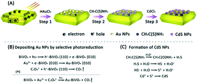
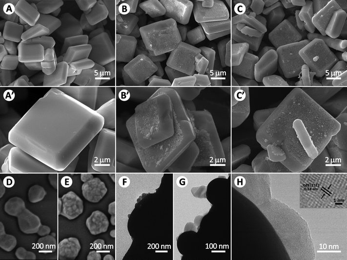
The synthetic route of the Z-scheme photocatalyst CdS–Au–BiVO4 is illustrated in Fig. 1A. Firstly, BiVO4 single crystals with a decagonal shape were prepared according to our previous work.20 Secondly, Au NPs were deposited on the {010} facets of BiVO4 crystals by a selective photo-reduction process using HAuCl4 as the Au source and H2C2O4 as the hole scavenger (step 1). The reaction equations for depositing Au NPs are shown in Fig. 1B. After absorbing light, BiVO4 crystals produce photo-generated electrons and holes, which transfer to the {010} and {110} facets, respectively, due to their different energy levels in the conduction bands and valence bands.23–28 Subsequently, the Au3+ ions are reduced to metallic Au0 by the electrons on the BiVO4 {010} facets. Meanwhile, the holes on the {110} facets are consumed by H2C2O4. In step 2, CH3CSNH2 are preferentially adsorbed on the surface of Au NPs, benefitting from the strong interaction between the sulfur-containing compound and Au surface.36,37 With the increase of temperature, CH3CSNH2 adsorbed on Au NPs are gradually hydrolyzed, as illustrated in Fig. 1C. Meanwhile, S2− ions are released and react with Cd2+ to form CdS on the surface of Au NPs (step 3).The morphologies of the as-prepared samples were observed by SEM (Fig. 2A–C and A′–C′), FE-SEM (D and E), and HR-TEM (Fig. 2F–H). As shown in Fig. 2A and A′, BiVO4 crystals exhibit a decagonal shape with an average side length of 8 μm and their surface seems to be clean and smooth. After depositing Au by photo-reduction, the {010} facets of BiVO4 crystals contain many Au NPs with size of ∼200 nm, while the {110} facets still remain bald (Fig. 2B and B′), which is because the photo-generated electrons selectively accumulate on the {010} facets of BiVO4 crystals. This is also evidence confirming the transfer pathway of photo-generated electrons. As shown in Fig. 2C and C′, the surface morphology of CdS–Au–BiVO4 has no evident change compared with that of Au–BiVO4. To further explore the state of CdS, the FE-SEM and HR-TEM images of Au–BiVO4 and CdS–Au–BiVO4 were further observed. As shown in Fig. 2D, the surface of Au particles on BiVO4 {010} facets looks bald before depositing CdS. In contrast, many hillocks appear on the surface of Au particles after depositing CdS (Fig. 2E). From the side view of the HR-TEM image (Fig. 2F and G), it can be clearly seen that CdS NPs (the grey ones) have been successfully deposited on the surface of Au NPs (the black ones). The lattice fringe pattern of CdS NPs was measured to be 0.34 nm (Fig. 2H), consistent with the interplanar spacing of the CdS (111) plane.34 Unfortunately, we failed to observe the lattice fringes of Au NPs and BiVO4 crystals because they are too thick to be transmitted by an electron beam.
3.2. Crystalline structure and surface composition
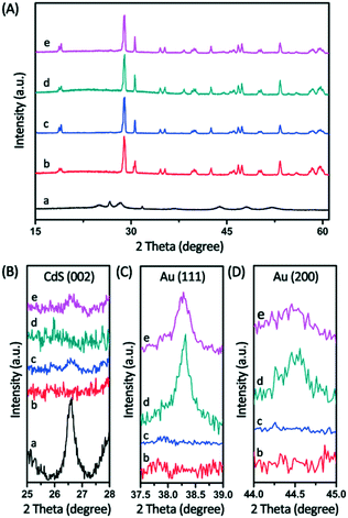
The X-ray diffraction patterns (XRD) of the different samples were analyzed to determine their crystallographic structures. As shown in Fig. 3A, all the samples BiVO4, Au–BiVO4, CdS–BiVO4, and CdS–Au–BiVO4 show the characteristic peaks of monoclinic scheelite phase BiVO4 (JCPDS file: 14-0688). Both Au–BiVO4 and CdS–Au–BiVO4 present two peaks at 38.2° and 44.3° (Fig. 3C and D), ascribed to the Au (111) and (200) diffraction peaks, respectively (JCPDS file: 80-0019). This result indicates that Au NPs have been successfully anchored on the BiVO4 surface. After CdS was deposited on the surface of Au NPs, CdS–Au–BiVO4 shows the (002) diffraction peak of cubic phase CdS (Fig. 3B) (JCPDS file: 41-1049). Similarly, the contrast sample CdS–BiVO4 also exhibits the (002) diffraction peak of CdS (Fig. 3B).To identify the elemental composition and chemical state of the as-prepared CdS–Au–BiVO4, X-ray photoelectron spectroscopy (XPS) analysis was performed. As shown in Fig. 4A, the XPS survey spectrum confirms the presence of Bi, O, V, Au, Cd, S, and C elements, in which the C comes from adventitious carbon. In Fig. 4B, the two peaks with binding energies of 159.1 eV and 164.4 eV can be attributed to Bi 4f7/2 and Bi 4f5/2, respectively. As displayed in Fig. 4C, the binding energies of V 2p3/2 and V 2p1/2 are located at 516.6 eV and 524.3 eV, respectively. In Fig. 4D, the peak at 529.8 eV can be ascribed to the lattice oxygen while the peak at 532.3 eV can be assigned to the adsorbed H2O and OH on the surface of CdS–Au–BiVO4.38,39 The binding energies of Bi, V, and O are consistent with those of monoclinic scheelite BiVO4.40Fig. 4E shows the XPS spectrum of Au 4f. The two peaks at 84.6 eV and 88.2 eV correspond to Au 4f7/2 and Au 4f5/2, respectively, of Au0, which confirms the existence of Au NPs in the composite.34 In Fig. 4F, the S 2s peak at 225.7 eV should be ascribed to the S2− in CdS.41 However, the S 2p peak cannot be found because it is covered by the strong Bi 4f peak. In Fig. 4G, the two peaks at 405.1 eV and 411.8 eV are attributed to Cd 3d5/2 and 3d3/2, respectively, which confirms the formation of CdS.35
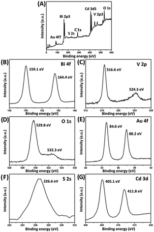 | ||
| Fig. 4 XPS spectra of the as-prepared CdS–Au–BiVO4: (A) survey spectrum; (B) Bi 4f; (C) V 2p; (D) O 1s; (E) Au 4f; (F) S 2s; (G) Cd 3d. | ||
3.3. Absorption and PL spectra
The light absorption properties of the samples BiVO4, CdS, Au–BiVO4, CdS–BiVO4 and CdS–Au–BiVO4 were analysed via UV-vis diffuse reflectance spectroscopy (DRS), as shown in Fig. 5A. Compared to BiVO4, both Au–BiVO4 and CdS–Au–BiVO4 exhibit a broad absorption peak around 620 nm, attributed to the surface plasmon resonance (SPR) absorption of Au NPs loaded on the {010} facets of BiVO4 crystals. Although the absorption edge of CdS exhibits an evident red shift compared with that of BiVO4, the absorption edge of CdS–BiVO4 is very near to that of BiVO4, which is due to the low CdS content in CdS–BiVO4. Compared to Au–BiVO4, the SPR absorption peak of CdS–Au–BiVO4 shows a red shift of 30 nm, which is due to the strong electromagnetic coupling between Au and CdS.42 Moreover, the SPR absorption intensity of CdS–Au–BiVO4 is slightly lower than that of Au–BiVO4, because the formed CdS NPs can hinder the SPR effect of Au NPs.43 The above results further confirm the formation of CdS NPs on the surface of Au NPs.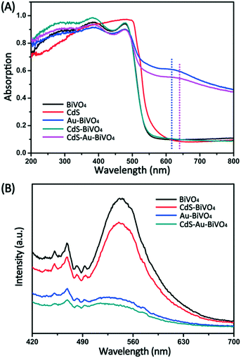 | ||
| Fig. 5 (A) UV-vis diffuse reflectance spectra of BiVO4, CdS, Au–BiVO4, CdS–BiVO4, and CdS–Au–BiVO4. (B) PL spectra of BiVO4, Au–BiVO4, CdS–BiVO4, and CdS–Au–BiVO4. | ||
Photoluminescence emission spectroscopy (PL) is considered to be a very useful technique to investigate the efficiency of charge carrier trapping, migration, and transfer of the photo-generated charge carriers in semiconductor particles.44–46Fig. 5B shows the PL spectra of BiVO4, Au–BiVO4, CdS–BiVO4, and CdS–Au–BiVO4. All samples CdS–BiVO4, Au–BiVO4, and CdS–Au–BiVO4 exhibit a weaker PL intensity compared with BiVO4, implying that the recombination rates of the photo-generated charge carriers in these samples have been restrained. The PL intensity of Au–BiVO4 is much lower than that of CdS–BiVO4, which indicates that depositing Au is a more effective strategy to reduce the recombination rate of charge carriers compared with coupling CdS. CdS–Au–BiVO4 displays the lowest PL intensity, implying that the photo-generated electron–hole pairs possess the highest transfer efficiency among the samples. For semiconductor materials, the lifetime of photo-generated charge carriers can be estimated by their fluorescence decay time. Table 1 shows the fluorescence decay times τ1 and τ2 of the different samples determined by their time-resolved fluorescence decay spectra. According to previous reports,47–49τ1 corresponds to the direct recombination of electrons and holes in the valence band, while τ2 is assigned to the charge carrier recombination during their transfer process. As shown in Table 1, the value of τ2 gradually increases in the order of BiVO4 < CdS–BiVO4 < Au–BiVO4 < CdS–Au–BiVO4, demonstrating that CdS–Au–BiVO4 with the Z-scheme structure possesses the highest ability for separating the photo-generated electrons and holes.50,51
| τ 1 (ns) | A 1 (%) | τ 2 (ns) | A 2 (%) | χ 2 | |
|---|---|---|---|---|---|
| BiVO4 | 0.146 | 97.0 | 2.617 | 3.0 | 1.124 |
| CdS–BiVO4 | 0.136 | 97.2 | 2.901 | 3.8 | 1.124 |
| Au–BiVO4 | 0.148 | 96.8 | 3.162 | 3.2 | 1.182 |
| CdS–Au–BiVO4 | 0.132 | 97.7 | 3.456 | 2.3 | 1.273 |
3.4. Photoelectrochemical properties
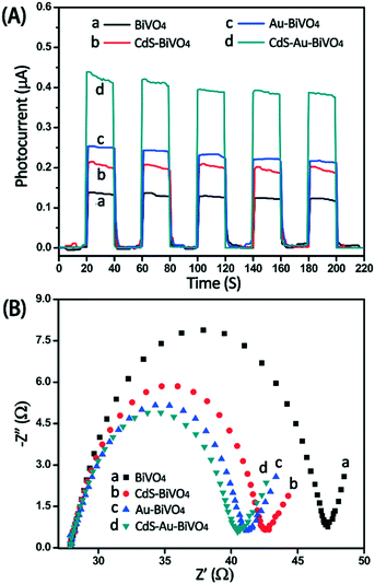
The transient photocurrents and electrochemical impedance spectra (EIS) were obtained to further investigate the transfer and separation efficiency of photo-generated carriers in the different samples. As shown in Fig. 6A, the photocurrents of the different samples follow the order of CdS–Au–BiVO4 > Au–BiVO4 > CdS–BiVO4 > BiVO4. Although all the samples CdS–BiVO4, Au–BiVO4, and CdS–BiVO4 show improved photocurrents compared to BiVO4, their mechanisms for enhancing photocurrents are different. For CdS–BiVO4, the separation efficiency of photo-generated electrons and holes is improved by forming a heterojunction structure between CdS and BiVO4, i.e., the photo-generated electrons transfer to the conduction band of BiVO4 while the holes transfer to the valence of CdS. With regard to Au–BiVO4, the Au NPs deposited on the BiVO4 {010} facets can form a Schottky barrier on the Au–BiVO4 interface, which can enhance the separation efficiency of charge carriers by trapping photo-generated electrons.52,53 In the case of CdS–Au–BiVO4, CdS and BiVO4 can form the Z-scheme with the participation of Au NPs, which can effectively separate the photo-generated electron–hole pairs.33–35Fig. 6B displays the Nyquist plots of the electrochemical impedance spectra of the different samples, which can be used to explore the dynamics of the mobile and bound charges in the interfacial or bulk region of the semiconductors.54,55 As shown in Fig. 6B, the semicircle diameters of CdS–Au–BiVO4, Au–BiVO4, and CdS–BiVO4 are smaller than that of BiVO4, revealing that these composite structures are more favorable to the carrier transfer than the single BiVO4.3.5. Photocatalytic activity and mechanism
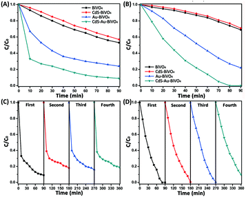
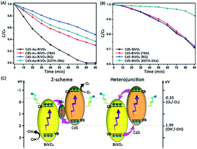
The photocatalytic activities of BiVO4, CdS–BiVO4, Au–BiVO4, and CdS–Au–BiVO4 were evaluated in terms of the degradations of TC and RhB under visible light irradiation. As shown in Fig. 7A and B, both Au–BiVO4 and CdS–Au–BiVO4 show evidently enhanced photocatalytic activity compared to BiVO4 for the degradations of TC and RhB. For instance, after visible light irradiation for 90 min, only 47% TC was degraded over BiVO4 while the degradation rates of TC over Au–BiVO4 and CdS–Au–BiVO4 reached 76% and 91%, respectively. For Au–BiVO4, the Au NPs can effectively improve the separation rate of photo-generated electrons and holes by forming a Schottky barrier,56,57 enhancing the photocatalytic activity of BiVO4. In the case of CdS–Au–BiVO4, the Z-scheme structure not only decreases the recombination rate of the photo-generated carriers but also makes the holes and electrons keep higher oxidation and reduction abilities, respectively (the reason will be discussed later). Therefore, CdS–Au–BiVO4 shows much higher photocatalytic activity than Au–BiVO4. Strangely, the heterojunction photocatalyst CdS–BiVO4 exhibits a lower photocatalytic activity than the single BiVO4, which is inconsistent with the results of photocurrent tests, implying that the photocatalytic activity is not totally determined by the separation rate of photo-generated carriers (the details will be discussed later). As photostability is very important to a photocatalyst for its practical application, here cyclic photocatalytic degradation experiments were carried out to investigate the photostability of CdS–Au–BiVO4. As displayed in Fig. 7C and D, the degradation rates of TC and RhB show only a little decrease after four cycles. Excluding the loss of photocatalyst in the cycling tests, CdS–Au–BiVO4 can be considered to be a stable photocatalyst.It is generally considered that organic pollutants can be degraded by photocatalytic oxidation processes, in which a series of reactive species, such as holes (h+), hydroxyl radicals (˙OH), and superoxide radicals (˙O2−), are involved in the degradation reactions of organic pollutants. To investigate the main reactive species responsible for the degradation of organic pollutants over heterojunction CdS–BiVO4 and Z-scheme CdS–Au–BiVO4, a series of contrast experiments in the presence of different quenchers were carried out. Here, tert-butyl alcohol (TBA) was used to quench ˙OH, EDTA-2Na for h+, and p-benzoquinone (BQ) for ˙O2−. As shown in Fig. 8A, after addition of EDTA-2Na or BQ, the photocatalytic activity of CdS–Au–BiVO4 decreases dramatically, indicating that all h+ and ˙O2− are the key reactive species responsible for the degradation of organic pollutants. The degradation rate of RhB shows a certain decrease in the presence of TBA, implying that ˙OH also takes part in the photocatalytic degradation of organic pollutants. In the case of CdS–BiVO4, the degradation rate of RhB exhibits an evident decrease after the addition of EDTA-2Na, while it almost has no change in the presence of MT and BQ (Fig. 8B), revealing that h+ plays a vital role in organic degradation.
On the basis of the above experimental results, the degradation mechanisms of organic pollutants over CdS–BiVO4 and CdS–Au–BiVO4 were proposed and illustrated in Fig. 8C. For the Z-scheme photocatalyst CdS–Au–BiVO4, when it is irradiated with visible light, the electrons will be excited to the conduction bands of BiVO4 and CdS while the holes will be left on their valence bands. Due to the excellent conductivity of the Au joint, the electrons on the BiVO4 conduction band (with weaker reduction ability) will combine with the holes on the CdS valence band (with weaker oxidation ability), while the holes on the BiVO4 valence band (with stronger oxidation ability) and the electrons on the CdS conduction band (with stronger reduction ability) will be preserved. Therefore, the electrons on the CdS conduction band easily combine with absorbed O2 to produce ˙O2−, while the holes on the BiVO4 valence band easily oxidize hydroxyl to form ˙OH. The formation of ˙O2− and ˙OH has been confirmed by the reactive species trapping experiments. Since the Z-scheme structure not only decreases the recombination rate of electrons and holes but also favors the formation of reactive species ˙OH and ˙O2−, CdS–Au–BiVO4 shows excellent photocatalytic activity for organic pollutant degradation. In the case of heterojunction CdS–BiVO4, the photo-generated electrons and holes will transfer to the conduction band of BiVO4 and the valence band of CdS, respectively. Due to the weak reduction ability of electrons as well as the poor oxidation ability of holes, almost no ˙OH and ˙O2− can be produced. Moreover, due to the weak oxidation ability of h+ on the CdS valence, CdS–BiVO4 exhibits lower photocatalytic activity.
4. Conclusions
In this work, a Z-scheme heterogeneous photocatalyst CdS–Au–BiVO4 was synthesized for the first time by photo-reduction and deposition–precipitation methods. By photo-reduction, Au NPs with an average size of 200 nm were successfully anchored on the {010} facets of BiVO4 crystals, in which the selective loading of Au NPs results from the oriented accumulation of electrons on the {010} facets. By the deposition–precipitation process, CdS was further selectively deposited on the surface of Au NPs via the strong S–Au interaction between the S precursor and Au NPs. CdS–Au–BiVO4 exhibited much higher photocatalytic activity for the degradation of TC and RhB when compared with BiVO4, Au–BiVO4, and CdS–BiVO4, which is because the Z-scheme structure of CdS–Au–BiVO4 not only decreases the recombination rate of photo-generated carriers but also makes the holes and electrons keep a higher redox ability. Radical trapping experiments proved that in the case of CdS–Au–BiVO4, the main reactive species responsible for organic contaminant degradation are h+, ˙OH, and ˙O2−, while only h+ can be produced in the case of CdS–BiVO4. As a highly efficient photocatalyst, the Z-scheme heterogeneous photocatalyst CdS–Au–BiVO4 can be potentially applied in wastewater treatment and other photocatalytic fields.Acknowledgements
This work has been supported by the National Natural Science Foundation of China (21277046, 21573069), the Shanghai Committee of Science and Technology (13NM1401000), and the National Basic Research Program of China (973 Program, 2013CB632403). We also thank the TEM Lab of Research Center of Analysis and Test of East China University of Science and Technology for kindly providing the TEM analysis.Notes and references
- K. Kümmerer, Chemosphere, 2009, 75, 417–434 CrossRef PubMed.
- R. P. Schwarzenbach, T. Egli, T. B. Hofstetter, U. Gunten and B. Wehrli, Annu. Rev. Environ. Resour., 2010, 35, 109–136 CrossRef.
- A. Azizullah, M. N. K. Khattak, P. Richter and D. P. Häder, Environ. Int., 2011, 37, 479–497 CrossRef CAS PubMed.
- L. Jiang, X. L. Hu, D. Q. Yin, H. C. Zhang and Z. Y. Yu, Chemosphere, 2011, 82, 822–828 CrossRef CAS PubMed.
- F. Han, V. S. R. Kambala, M. Srinivasan, D. Rajarathnam and R. Naidu, Appl. Catal., A, 2009, 359, 25–40 CrossRef CAS.
- L. L. Ji, Y. Q. Wan, S. R. Zheng and D. Q. Zhu, Environ. Sci. Technol., 2011, 45, 5580–5586 CrossRef CAS PubMed.
- P. Rajaguru, L. Vidya, B. Baskarasethupathi, P. A. Kumar, M. Palanivel and K. Kalaiselvi, Mutat. Res., 2002, 517, 29–37 CAS.
- M. C. L. S. Coelho, C. A. Coimbrão, G. U. Valent, M. I. Z. Sato, P. S. Sanchez and H. Targa, Environ. Mol. Mutagen., 1992, 19, 199–211 Search PubMed.
- P. S. Sanchez, M. I. Z. Sato, C. M. R. B. Paschoal, M. N. Alves, E. V. Furlan and M. T. Martins, Toxic. Assess., 1988, 3, 55–80 CrossRef CAS.
- I. R. Bautitz and R. F. P. Nogueira, J. Photochem. Photobiol., A, 2007, 187, 33–39 CrossRef CAS.
- R. A. Palominos, M. A. Mondaca, A. Giraldo, G. Peñuela, M. P. Moya and H. D. Mansilla, Catal. Today, 2009, 144, 100–105 CrossRef CAS.
- P. H. Wang, P. S. Yap and T. T. Lim, Appl. Catal., A, 2011, 399, 252–261 CrossRef CAS.
- B. Z. Tian, T. T. Wang, R. F. Dong, S. Y. Bao, F. Yang and J. L. Zhang, Appl. Catal., B, 2014, 147, 22–28 CrossRef CAS.
- R. F. Dong, B. Z. Tian, C. Y. Zeng, T. Y. Li, T. T. Wang and J. L. Zhang, J. Phys. Chem. C, 2013, 117, 213–220 CAS.
- R. Hao, X. Xiao, X. X. Zuo, J. M. Nan and W. D. Zhang, J. Hazard. Mater., 2012, 209, 137–145 CrossRef PubMed.
- X. Xiao, R. P. Hu, C. Liu, C. L. Xing, X. X. Zuo, J. M. Nan and L. S. Wang, Chem. Eng. J., 2013, 225, 790–797 CrossRef CAS.
- Y. Z. Hong, C. S. Li, G. Y. Zhang, Y. D. Meng, B. X. Yin, Y. Zhao and W. D. Shi, Chem. Eng. J., 2016, 299, 74–84 CrossRef CAS.
- E. A. S. Galvis, J. S. Agredo, A. L. Giraldo, O. A. F. Acosta and R. A. T. Palma, Sci. Total Environ., 2016, 541, 1431–1438 CrossRef PubMed.
- N. F. F. Moreira, J. M. Sousa, G. Macedo, A. R. Ribeiro, L. Barreiros, M. Pedrosa, J. L. Faria, M. F. R. Pereira, S. C. Silva, M. A. Segundo, C. M. Manaia, O. C. Nunes and A. M. T. Silva, Water Res., 2016, 94, 10–22 CrossRef CAS PubMed.
- Q. F. Wu, S. Y. Bao, B. Z. Tian, Y. F. Xiao and J. L. Zhang, Chem. Commun., 2016, 52, 7478–7481 RSC.
- Z. F. Huang, L. Pan, J. J. Zou, X. W. Zhang and L. Wang, Nanoscale, 2014, 6, 14044–14063 RSC.
- M. Zhou, H. B. Wu, J. Bao, L. Liang, X. W. Lou and Y. Xie, Angew. Chem., Int. Ed., 2013, 52, 8579–8583 CrossRef CAS PubMed.
- R. G. Li, F. X. Zhang, D. G. Wang, J. X. Yang, M. R. Li, J. Zhu, X. Zhou, H. X. Han and C. Li, Nat. Commun., 2013, 4, 1432 CrossRef PubMed.
- J. Zhu, F. T. Fan, R. T. Chen, H. Y. An, Z. C. Feng and C. Li, Angew. Chem., 2015, 127, 9239–9242 CrossRef.
- F. Lin, D. G. V. Wang, Z. X. Jiang, Y. Ma, J. Li, R. G. Li and C. Li, Energy Environ. Sci., 2012, 5, 6400–6406 CAS.
- D. Wang, R. G. Li, J. Zhu, J. Y. Shi, J. F. Han, X. Zong and C. Li, J. Phys. Chem. C, 2012, 116, 5082–5089 CAS.
- R. G. Li, H. X. Han, F. X. Zhang, D. Wang and C. Li, Energy Environ. Sci., 2014, 7, 1369–1376 CAS.
- J. X. Yang, D. Wang, X. Zhou and C. Li, Chem. – Eur. J., 2013, 19, 1320–1326 CrossRef CAS PubMed.
- H. L. Zhou, Y. Q. Qu, T. Zeid and X. F. Duan, Energy Environ. Sci., 2012, 5, 6732–6743 CAS.
- X. B. Chen, L. Liu, P. Y. Yu and S. S. Mao, Science, 2011, 331, 746–750 CrossRef CAS PubMed.
- Z. Q. He, Y. Q. Shi, C. Gao, L. Wen, J. M. Chen and S. Song, J. Phys. Chem. C, 2013, 118, 389–398 Search PubMed.
- W. Z. Wang, X. W. Huang, S. Wu, Y. X. Zhou, L. J. Wang, H. L. Shi, Y. J. Liang and B. Zou, Appl. Catal., B, 2013, 134, 293–301 CrossRef.
- P. Zhou, J. G. Yu and M. Jaroniec, All-Solid-State Z-Scheme Photocatalytic Systems, Adv. Mater., 2014, 26, 4920–4935 CrossRef CAS PubMed.
- W. B. Li, C. Feng, S. Y. Dai, J. G. Yue, F. X. Hua and H. Hou, Appl. Catal., B, 2015, 168, 465–471 CrossRef.
- Z. B. Yu, Y. P. Xie, G. Liu, G. Q. Lu, X. L. Ma and H. M. Cheng, J. Mater. Chem. A, 2013, 1, 2773–2776 CAS.
- H. Tada, F. Suzuki, S. Ito, T. Akita, K. Tanaka, T. Kawahara and H. Kobayashi, J. Phys. Chem. B, 2002, 106, 8714–8720 CrossRef CAS.
- H. Tada, T. Mitsui, T. Kiyonaga, T. Akita and K. Tanaka, Nat. Mater., 2006, 5, 782–786 CrossRef CAS PubMed.
- L. Zhang, D. R. Chen and X. L. Jiao, J. Phys. Chem. B, 2006, 110, 2668–2673 CrossRef CAS PubMed.
- L. Ge, Mater. Chem. Phys., 2008, 107, 465–470 CrossRef CAS.
- G. S. Li, D. Q. Zhang and J. C. Yu, Chem. Mater., 2008, 20, 3983–3992 CrossRef CAS.
- P. Ardalan, T. P. Brennan, H. B. R. Lee, J. R. Bakke, I. K. Ding, M. D. McGehee and S. F. Bent, ACS Nano, 2011, 5, 1495–1504 CrossRef CAS PubMed.
- I. Honma, T. Sano and H. Komiyama, J. Phys. Chem., 1993, 97, 6692–6695 CrossRef CAS.
- H. Y. Li, Y. J. Sun, B. Cai, S. Y. Gan, D. X. Han, L. Niu and T. S. Wu, Appl. Catal. B, 2015, 170, 206–214 CrossRef.
- B. Weng, S. Q. Liu, N. Zhang, Z. K. Tang and Y. J. Xu, A Simple Yet Efficient Visible-Light-Driven CdS Nanowires-Carbon Nanotube 1D-1D Nanocomposite Photocatalyst, J. Catal., 2014, 309, 146–155 CrossRef CAS.
- B. Z. Tian, C. Z. Li, F. Gu and H. B. Jiang, Catal. Commun., 2009, 10, 925–929 CrossRef CAS.
- Y. Liu, P. Zhang, B. Z. Tian and J. L. Zhang, ACS Appl. Mater. Interfaces, 2015, 7, 13849–13858 CAS.
- Z. Q. Xu, H. Li, Z. C. Wu, J. Sun, Z. F. Ying, J. D. Wu and N. Xu, J. Mater. Chem. C, 2016, 4, 7501–7507 RSC.
- J. D. Keene, J. R. McBride, N. J. Orfield and S. J. Rosenthal, ACS Nano, 2014, 8, 10665–10673 CrossRef CAS PubMed.
- H. N. Ghosh and S. Adhikari, Langmuir, 2001, 17, 4129–4130 CrossRef CAS.
- Y. K. Kim, S. M. Sharker, I. In and S. Y. Park, Carbon, 2016, 103, 412–420 CrossRef CAS.
- P. Thakur, S. S. Joshi, S. Kapoor and T. Mukherjee, Langmuir, 2009, 25, 6377–6384 CrossRef CAS PubMed.
- V. Subramanian, E. E. Wolf and P. V. Kamat, J. Am. Chem. Soc., 2004, 126, 4943–4950 CrossRef CAS PubMed.
- A. Iwase, H. Kato and A. Kudo, Catal. Lett., 2006, 108, 7–10 CrossRef CAS.
- D. F. Zhang, J. Phys. Chem. A, 2012, 86, 93–99 CAS.
- C. Karunakaran, P. Gomathisankar and G. Manikandan, Mater. Chem. Phys., 2010, 123, 585–594 CrossRef CAS.
- M. Murdoch, G. I. N. Waterhouse, M. A. Nadeem, J. B. Metson, M. A. Keane, R. F. Howe, J. Llorca and H. Idriss, Nat. Chem., 2011, 3, 489–492 CAS.
- M. Jakob and H. Levanon, Nano Lett., 2003, 3, 353–358 CrossRef CAS.
Footnote |
| † Shenyuan Bao and Qiangfang Wu contributed equally to this work. |
| This journal is © The Royal Society of Chemistry 2017 |

