On-demand magnetic manipulation of liquid metal in microfluidic channels for electrical switching applications†
Jinpyo
Jeon
a,
Jeong-Bong
Lee
b,
Sang Kug
Chung
*a and
Daeyoung
Kim
*c
aDepartment of Mechanical Engineering, Myoungji University, Yongin, 449-728, Republic of Korea. E-mail: junjynpyo@mju.ac.kr; skchung@mju.ac.kr; Fax: +82 31 330 6346; Tel: +82 31 330 6346
bDepartment of Electrical Engineering, The University of Texas at Dallas, Richardson, TX 75080, USA. E-mail: jblee@utdallas.edu
cDepartment of Information and Communication Engineering, Korea Army Academy at Yeong-cheon, 770-849, South Korea. E-mail: jokuksarang64@gmail.com
First published on 17th November 2016
Abstract
We report magnetic-field-driven on-demand manipulation of liquid metal in microfluidic channels filled with base or acid. The liquid metal was coated with iron (Fe) particles and treated with hydrochloric acid to have strong bonding strength with the Fe particles. The magnetic liquid metal slug inserted in the microchannel is manipulated, merged, and separated. In addition, corresponding to the repositioning of an external magnet, the liquid metal slug can be readily moved in microfluidic channels with different angles (>90°) and cross-linked channels in any direction. We demonstrated the functionality of the liquid metal in the microfluidic channel for electrical switching applications by manipulation of the liquid metal, resulting in the sequential turning on of light emitting diodes (LEDs).
1. Introduction
On-demand manipulation of small amounts of liquid in a controlled manner in microfluidics holds great potential for diverse applications. The methods of manipulating a variety of liquids in micro/nano-fluidics have been extensively investigated utilizing physical, electrical, chemical, optical, and their combinational phenomena.1–6 Recently, ‘liquid metal’ which is in a liquid state at room temperature was introduced, and it was followed by numerous applications such as soft electronics,7–10 wearable electronics,11,12 and reconfigurable applications.13,14 Among various liquid metals, gallium-based liquid metal alloys, e.g. Galinstan15 or e-GaIn,16 have been widely studied because they have preferable material properties such as high thermal and electrical conductivities as well as non-toxicity.17,18 Although liquid metal shows great promise for a wide variety of potential applications, the range of applicability of the liquid metal has been limited, as the liquid metal easily oxidizes in an air environment and wets on almost any surface. Thus, it is very challenging to manipulate the liquid metal using its mobility. There have been many efforts to manipulate the liquid metal using various approaches such as the pneumatic method,19 electrochemical method,20,21 magnetic method,22,23 and slip layer insertion method.24 Among them, the method which can be applied to the manipulation ‘in microfluidic channels’ is extremely limited. Only the electrochemical method can be applied in microfluidic channels to actuate the liquid metal inside the channel.25 However, in order to apply bias, it needs to have conductive metals acting as electrodes in microfluidic channels, which requires an additional fabrication process.In this study, we demonstrate magnetic-field-driven on-demand manipulation of liquid metal in microfluidic channels. To the best of our knowledge, this is the first investigation into magnetic on-demand actuation of liquid metal in microfluidic channels. To maintain the non-wetting properties of the liquid metal, either base (NaOH) or acid (HCl) was partly or fully filled in the microfluidic channels. We studied the delay time and the velocity ratio of the moving liquid metal and magnet to characterize the dynamic behaviour of manipulation under diverse channel conditions: various channel widths ranging from 0.5 mm to 2 mm; base or acid in the microfluidic channels; fully or partly filled channels; various bottom PDMS thicknesses ranging from 0.5 mm to 4 mm. The liquid metal was successfully manipulated in the crooked channels with different angles (>90°) and the cross-linked channels in any direction. We finally investigated the electrical switching applicability in the microfluidic channels using this method by turning on LEDs.
2. Materials and methods
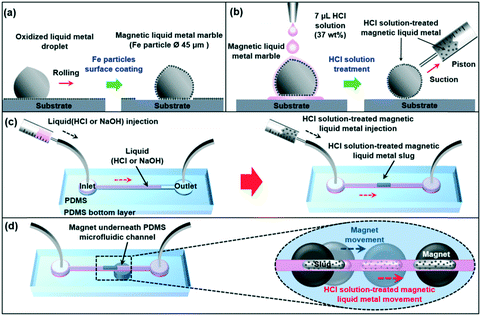
Magnetic liquid metal was obtained by coating ferromagnetic iron (Fe) particles onto an oxidized Galinstan droplet by rolling the liquid metal droplet on a bed of Fe particles (diameter of 45 μm) as shown in Fig. 1a. Due to its gel-like tacky oxidized surface, Fe particles easily attached to the surface of the Galinstan droplet. Once it was coated with Fe particles, the liquid metal can be actuated by applying an external magnetic field. The Fe-coated liquid metal droplet was then treated with HCl solution. We dropped the ∼7 μL HCl droplet (37 wt%) onto the ∼8 μL Fe-coated liquid metal droplet. The oxidized surface and coated iron particles were readily reacted with the HCl solution. HCl solution treatment can convert the oxide layer to a non-wetting gallium/indium chloride layer and change the surface tension by chemical reaction with the oxide layer.26 It also reacted with the coated Fe particles and increased the adhesion strength between the Fe particles27 and the surface of the liquid metal. After HCl solution treatment, compared to that of the oxidized magnetic liquid metal, the shape of the HCl solution-treated magnetic liquid metal was totally changed to a ‘true spherical droplet shape’. The HCl solution-treated magnetic liquid metal was then placed in a syringe (Model KOVAX 10 mL, KOREA VACCINE CO.) by suction (Fig. 1b). The microfluidic channel was fabricated with polydimethylsiloxane (PDMS) using soft photolithography (please refer to the ESI†).The microfluidic channel was composed of circle-shaped inlet and outlet ports (diameter of 5 mm) linked to a straight ∼38 mm long and 500 μm wide channel (bottom PDMS thickness was 2 mm). We filled the channel with base (NaOH, 0.5 M) or acid (HCl, 37 wt%) to prevent surface oxidation of the liquid metal.26,28 In order to study the dynamic behavior of the magnetic manipulation of the liquid metal in the microfluidic channel, we partly filled the channel with a small amount of base or acid (∼20 μL). After filling in, pneumatic pressure (16 kPa) was applied to push the acid or base further into the microfluidic channel. Since the channel was fabricated with gas-permeable PDMS,29 the acid or base readily permeated into PDMS and, by visual inspection, little acid or base remained in the channel. Then, we injected the HCl solution-treated magnetic liquid metal into the microfluidic channel. The liquid metal had a form of slug (Fig. 1c). By positioning a cylinder-shaped magnet (maximum magnetic flux density of 2000 gauss, diameter of 5 mm) underneath the microfluidic channel, the HCl solution-treated magnetic liquid metal slug was readily controlled along the moving direction of the magnet (Fig. 1d).
3. Results and discussion
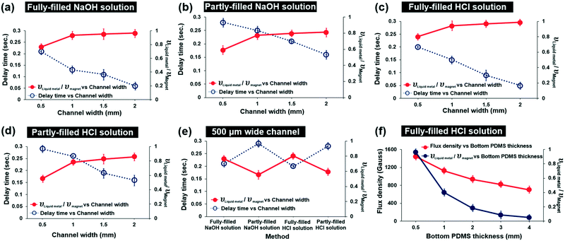
In order to find the optimum conditions of the microchannels, we studied the delay time of the HCl-treated magnetic liquid metal and the velocity ratio of the moving liquid metal and the moving magnet under different channel conditions: 1) fully or partly filled with HCl or NaOH solution, 2) channel width (0.5, 1, 1.5, 2 mm), and 3) bottom PDMS thickness (0.5, 1, 2, 3, 4 mm) (Fig. 2). We first observed that the HCl solution-treated magnetic liquid metal was not immediately moved due to friction, even though the magnet was re-positioned. Thus, we calculated the delay time by measuring the time difference of the moving magnet and the moving magnetic liquid metal (blue-colored dotted line in Fig. 2). In addition, we also calculated the velocity ratio of the moving liquid metal and magnet (red-colored solid line in Fig. 2). These delay time and velocity ratio of the moving liquid metal and magnet characterize the dynamic behavior during the actuation under the applied magnetic field.As shown in Fig. 2(a)–(d), in all cases of microfluidic channels fully or partly filled with NaOH or HCl, the velocity ratio increased with wider channel width, while the delay time decreased with wider channel width. As the channel width increases, the larger volume of the HCl-treated magnetic liquid metal can be manipulated under the same amount of the applied magnetic field. Thus, the amount of the attached Fe particles also proportionally increases. This induces a larger pulling magnetic force, resulting in the contribution to the fast response and high velocity. The shortest delay time of 0.05 s and the highest velocity ratio of 0.96 were achieved in the 2 mm wide HCl fully-filled channel.
Regardless of the liquid, as long as the amount of the liquid (acid or base) filled into the channel is the same, the trends of delay time and the velocity of the magnetic manipulation against the channel width are very similar. For the liquid fully-filled channel, the delay time is in the range of 0.05–0.2 s and the velocity ratio already reaches ‘1’ when the channel widths are close to 1 mm. However, for the liquid partly-filled channel, the delay time is in the range of 0.15–0.3 s and the velocity ratio does not reach ‘1’ even with a 2 mm wide channel. This indicates that the liquid fully-filled channels show better dynamic performance of the manipulation than the liquid partly-filled channels, as the friction between the magnetic liquid metal and the surface of the microfluidic channel is largely decreased and the surface tension of the liquid metal is kept high by chemical reaction with the base/acid. Comparing the delay time and the velocity ratio in 500 μm wide microfluidic channels fully/partly filled with NaOH/HCl solution (Fig. 2e), the shortest delay time and the largest velocity ratio were achieved to be 0.2 s and 0.8 in the HCl fully-filled channel.
We investigated the magnetic field intensity using a gaussmeter against various bottom PMDS thicknesses (0.5, 1, 2, 3, 4 mm) which determine the distance between the magnet and the liquid metal in the microfluidic channel (Fig. 2f). The magnetic flux density exponentially decreased as the bottom PDMS thickness increased. We found that the applied magnetic flux density was measured to be 1400 gauss with the 500 μm thick bottom PDMS. We also investigated the velocity ratio of the moving HCl treated-magnetic liquid metal and the magnet, which exponentially decreased due to the increased thickness of the bottom PDMS layer with an applied magnetic field at the 500 μm wide channel. As the applied magnetic field was decreased by increasing the gap distance between the magnet and the liquid metal, the velocity of the moving liquid metal accordingly decreased. We have investigated how long the manipulation can be maintained when HCl evaporates. Under HCl solution fully-filled conditions, the liquid metal can be manipulated within 8 hours of evaporation. Under HCl solution partly-filled conditions, the manipulation lasted until 3 hours of evaporation. However, when HCl was refilled into the channel, the liquid metal can be manipulated again.
Based on the study of the dynamic performance for magnetic liquid metal manipulation, the optimum condition of the magnetic liquid metal manipulation in the microfluidic channel is the wider and HCl fully-filled channel with the thinner bottom PDMS layer as expected.
We further investigated on-demand magnetic manipulation of the HCl treated-magnetic liquid metal with an applied magnetic field in the HCl fully-filled, 500 μm wide microfluidic channel with a 2 mm thick PDMS bottom layer. Fig. 3a shows the conceptual schematic of the magnetic field-driven liquid metal manipulation, separation, and merging in the microfluidic channel. First, magnetic liquid metal manipulation was carried out by placing the magnet underneath the PDMS bottom layer. By changing the position of the magnet arbitrarily along the microfluidic channel, the position of the HCl solution-treated magnetic liquid metal slug was manipulated on demand. Next, two magnets were placed and moved in the opposite direction to each other, resulting in separation of the magnetic liquid metal slug into two. Then, by moving the magnet(s) underneath the microfluidic channel, the separated liquid metal slugs were moved and merged quickly with each other (Fig. 3b, please refer to Movies S1 and S2†).
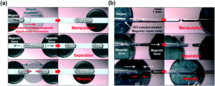 | ||
| Fig. 3 (a) Conceptual schematics and (b) optical images of magnetic-field-driven on-demand manipulation, separation, and merging of liquid metal in a microfluidic channel (please refer to Movie S1†). | ||
Based on the on-demand manipulation study of the HCl-treated magnetic liquid metal in the microfluidic channel, we further investigated the magnetic manipulation in the microfluidic channel with a series of different angle turns. We designed and fabricated a 500 μm wide channel having different angles from 90° to 125° with 5° differences. The overall size of the channel was 35 mm × 30 mm with a 5 mm thick PDMS bottom layer (Fig. 4a). Fig. 4b shows the time-lapse images of the sequential movement of the HCl-treated magnetic liquid metal slug in the arbitrary sharp-angled microfluidic channel (please refer to Movie S3†). By positioning the magnet underneath the channel, the magnetic liquid metal was readily moved along the microfluidic channel. However, we found that the magnetic liquid metal slug could be separated into two slugs in microfluidic channels with 90° turn or smaller angles (Fig. 4b).
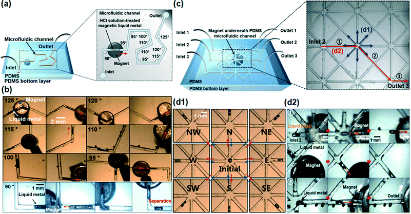 | ||
| Fig. 4 (a and c) Conceptual schematics of on-demand magnetic liquid metal manipulation in the crooked channel and the spiderweb-like, cross-linked channel; (b) time-lapse images of moving HCl solution-treated magnetic liquid metal in the channels at angles ranging from 90° to 125°. The HCl solution-treated magnetic liquid metal slug was separated in the 90° angle crooked channel; (d1) time-lapse images of reversibly manipulated HCl solution-treated magnetic liquid metal to/from 8 different directions in the spiderweb-like, cross-linked channel; (d2) time-lapse images of the moving HCl solution-treated magnetic liquid metal slug from inlet 2 to outlet 3 (please refer to Movies S3 and S4†). Note that those defects/in the optical images were air bubbles formed during the fabrication process. | ||
We also studied the microfluidic-based magnetic manipulation of the liquid metal in the spiderweb-like, cross-linked complex channels in any direction. The channel had three inlets (diameter of 5 mm) and three outlets (diameter of 5 mm), 500 μm width and eight-linked branch channels in one cross point (Fig. 4c, inset). The channel was partly filled with HCl. The magnetic liquid metal was manipulated from one cross point into 8 different branch channels (Fig. 4d1) which are 45 degrees apart from each other. It was also injected from inlet ‘2’ and ejected to outlet ‘3’ by controlling the applied magnetic field (please refer to Movie S4†). We demonstrated that the magnetic liquid metal slug was successfully manipulated into any direction in the spiderweb-like microfluidic channels.
Based on these studies, we applied this magnetic liquid metal slug manipulation for electrical switching applications (Fig. 5).
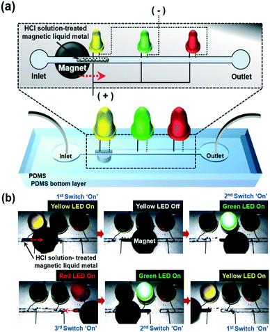 | ||
| Fig. 5 (a) Conceptual schematic of investigating the functionality of the magnetic liquid metal for electrical switching applications in a microfluidic channel and (b) time-lapse images of turning on LEDs by manipulation of the magnetic liquid metal with an applied magnetic field (please refer to Movie S5†). | ||
4. Conclusions
We investigated a simple but very effective method for microfluidic-based on-demand magnetic manipulation of liquid metal. The liquid metal was coated with Fe particles and functionalized with HCl. Dynamic characterization of the magnetic manipulation including the delay time and velocity ratio indicated that the wider channel, fully filled with HCl or NaOH having a thinner PDMS bottom layer, was the optimum condition. On-demand magnetic manipulation was successfully demonstrated in the microfluidic channels with a series of arbitrary angled turns with different angles (>90°) and the cross-linked channels in any direction. The electrical switching application was demonstrated using the liquid metal's conductivity, mobility, and magnetic controllability. This can be a promising method to utilize the liquid metal's mobility in microfluidic channels and it would widely expand the liquid metal's applicability for diverse practical uses.Acknowledgements
This research was supported by the Basic Science Research Program through the National Research Foundation of Korea (NRF) funded by the Ministry of Education (2015R1D1A1A02062153). This research was supported in part by the Republic of Korea (ROK) Army.Notes and references
- A. Wixforth, C. Strobl, C. Gauer, A. Toegl, J. Scriba and Z. V. Guttenberg, Anal. Bioanal. Chem., 2004, 379, 982–991 CrossRef CAS PubMed.
- M. G. Pollack and R. B. Fair, Appl. Phys. Lett., 2000, 77, 1725–1726 CrossRef CAS.
- T. B. Jones, M. Gunji, M. Washizu and M. J. Feldman, Appl. Phys. Lett., 2001, 89, 1441–1448 CAS.
- W. Hu and A. T. Ohta, Microfluid. Nanofluid., 2011, 11, 307–316 CrossRef.
- P. Y. Chiou, Z. Chang and M. C. Wu, J. Microelectromech. Syst., 2008, 17, 133–138 CrossRef.
- S. Fujii, S.-I. Yusa and Y. Nakamura, Adv. Funct. Mater., 2016, 26, 7206–7223 CrossRef CAS.
- J. H. So, J. Thelen, A. Qusba, G. J. Hayes, G. Lazzi and M. D. Dickey, Adv. Funct. Mater., 2009, 19, 3632 CrossRef CAS.
- H. J. Koo, J. H. So, M. D. Dickey and O. D. Velev, Adv. Mater., 2011, 23, 3559 CrossRef CAS PubMed.
- E. Palleau, S. Reece, S. C. Desai, M. E. Smith and M. D. Dickey, Adv. Mater., 2013, 25, 1589 CrossRef CAS PubMed.
- Q. Wang, Y. Yu, J. Yang and J. Liu, Adv. Mater., 2015, 27, 7109–7116 CrossRef CAS PubMed.
- R. Matsuzaki and K. Tabayashi, Adv. Funct. Mater., 2015, 25, 3806–3813 CrossRef CAS.
- L. Sheng, S. Teo and J. Liu, J. Med. Biol. Eng., 2016, 36, 265–272 CrossRef.
- M. Kelley, C. Koo, H. McQuilken, B. Lawrence, S. Li, A. Han and G. Huff, Electron. Lett., 2013, 49, 1370–1371 CrossRef.
- B. L. Cumby, G. J. Hayes, M. D. Dickey, R. S. Justice, C. E. Tabor and J. C. Heikenfeld, Appl. Phys. Lett., 2012, 101, 174102 CrossRef.
- P. Sen and C.-J. Kim, Microscale Liquid-Metal Switches—A Review, IEEE Trans. Ind. Electron., 2009, 56(4), 1314–1330 CrossRef.
- R. C. Chiechi, E. A. Weiss, M. D. Dickey and G. M. Whitesides, Angew. Chem., 2008, 120, 148–150 CrossRef.
- S. Cheng and Z. Wu, Lab Chip, 2012, 12, 2782–2791 RSC.
- T. Liu, P. Sen and C. J. Kim, J. Microelectromech. Syst., 2012, 21, 443–450 CrossRef CAS.
- D. Kim, D. W. Lee, W. Choi and J. B. Lee, J. Microelectromech. Syst., 2013, 22, 1267–1275 CrossRef CAS.
- S. Y. Tang, V. Sivan, K. Khoshmanesh, A. P. O'Mullane, X. Tang, B. Gol, N. Eshtiaghi, F. Lieder, P. Petersen, A. Mitchell and K. Kalantar-zadeh, Nanoscale, 2013, 5, 5949–5957 RSC.
- C. B. Eaker and M. D. Dickey, Appl. Phys. Rev., 2016, 3, 031103 Search PubMed.
- D. Kim and J. B. Lee, J. Korean Phys. Soc., 2015, 66, 282–286 CrossRef CAS.
- L. Wang and J. Liu, Proc. R. Soc. A, 2015, 471(2178), 20150177 CrossRef.
- M. R. Khan, C. Trlica, J. H. So, M. Valeri and M. D. Dickey, ACS Appl. Mater. Interfaces, 2014, 6, 22467–22473 CAS.
- M. R. Khan, C. Trlica and M. D. Dickey, Adv. Funct. Mater., 2015, 25, 671–678 CrossRef CAS.
- D. Kim, P. Thissen, G. Viner, D. W. Lee, W. Choi, Y. J. Chabal and J. B. Lee, ACS Appl. Mater. Interfaces, 2012, 5, 179–185 Search PubMed.
- R. Guicheteau, J. L. Bobet, Y. F. Lu, M. L. Troedec and J. F. Silvain, J. Mater. Sci. Eng., 2015, 4, 1000194 Search PubMed.
- B. Gol, F. J. Tovar-Lopez, M. E. Kurdzinski, S. Y. Tang, P. Petersen, A. Mitchell and K. Khoshmanesh, Lab Chip, 2015, 15, 2476–2485 RSC.
- G. Li, M. Parmar, D. Kim, J. B. Lee and D. W. Lee, Lab Chip, 2014, 14, 200–209 RSC.
Footnote |
| † Electronic supplementary information (ESI) available. See DOI: 10.1039/c6lc01255h |
| This journal is © The Royal Society of Chemistry 2017 |

