Metal–organic framework derived hollow CoS2 nanotube arrays: an efficient bifunctional electrocatalyst for overall water splitting†
Cao
Guan
 *,
Ximeng
Liu
,
Abdelnaby M.
Elshahawy
,
Hong
Zhang
,
Haijun
Wu
*,
Stephen J.
Pennycook
and
John
Wang
*
*,
Ximeng
Liu
,
Abdelnaby M.
Elshahawy
,
Hong
Zhang
,
Haijun
Wu
*,
Stephen J.
Pennycook
and
John
Wang
*
Department of Materials Science and Engineering, National University of Singapore, 117574, Singapore. E-mail: msegc@nus.edu.sg; wu.haijun@u.nus.edu; msewangj@nus.edu.sg
First published on 30th June 2017
Abstract
Self-supported hollow nanoarrays with hierarchical pores and rich reaction sites are promising for advanced electrocatalysis. Herein, we report a rational design of novel CoS2 nanotube arrays assembled on a flexible support which can be directly utilized as an efficient bifunctional electrocatalyst for overall water splitting. Uniform wire-like metal–organic framework (MOF) nanoarrays were first fabricated and a sulfidation process by thermal treatment was carried out to transform the MOF arrays into CoS2 nanotube arrays. The unique hollow CoS2 tubular arrays are shown to provide high surface area for an efficient electrochemical reaction, and the well-defined electrical/mechanical connection to the substrate enhances both mass and electron transfer. The CoS2 nanotube arrays exhibited a high electrochemical activity in catalyzing both oxygen and hydrogen evolution reactions, in terms of low onset potential, high current density and excellent stability. Using the CoS2 nanotube arrays as catalysts, a water-splitting current density of 10 mA cm−2 in alkaline solution is achieved with a cell voltage of 1.67 V, and the stable current can be maintained for 20 h even when the electrode is in a bent state.
Conceptual insightsMetal–organic frameworks (MOFs) and their derivatives have received considerable attention due to their unique structures and widespread applications in electrocatalysis. However, most of the previous studies on MOF-based/derived materials were focused on particle-like structures, and the electrode materials were prepared in powdered forms with a polymer binder and carbon additives. Herein, a novel hollow CoS2 nanotube array has been rationally designed on a flexible carbon cloth substrate from a MOF precursor. The resulting hollow and porous structure can provide rich reaction sites and short ion diffusion length, and it can be directly used as a flexible catalyst for both the oxygen evolution reaction and the hydrogen evolution reaction with high electrochemical performance. Such MOF derived hollow arrays can pave the way for the design of advanced electrochemical conversion devices. |
Electrochemical water-splitting has been considered as a promising approach to produce clean hydrogen (H2) fuel.1–3 For efficient water-splitting consisting of two half-reactions of the oxygen evolution reaction (OER) and the hydrogen evolution reaction (HER), effective catalysts with low over potential, high activity, and stability are urgently required.4 Currently, Pt-based materials are considered as being among the state-of-the-art catalysts for the HER, while Ir/Ru materials are among the benchmark electrocatalysts for the OER. However, these noble-metal based catalysts suffer from relative scarcity and high cost; thus, considerable research efforts have been made to develop novel electrocatalysts with both high catalytic performance and low cost.5–8 A number of alternatives including transition metal sulfides, selenides, phosphides, and nanocomposites have been investigated as potential substitutes for noble-metal catalysts for the HER in acidic solutions, and transition metal oxides, hydroxides, phosphates, and carbon nitride have been reported with good activity for the OER in an alkaline environment.9–16 Since both HER and OER catalysts should be assembled in the same electrolyzer, bifunctional catalysts capable of running in the same electrolyte are required in order to simplify the system and reduce the overall cost.17–20 With these understandings, transition metal oxides, sulfides, phosphates and perovskite oxides have been reported as effective bifunctional catalysts under alkaline conditions.21–27 For such catalysts, properly-defined porous and/or hollow materials are highly desirable, since they can provide a large surface area, a kinetically favorable open structure, and a shortened ion diffusion length.28,29
In recent studies, MOFs have been utilized as efficient precursors and templates to construct porous and hollow structured electrodes, owing to their well-tunable physical and chemical properties with large surface area.30–38 For example, multishell mixed-metal oxyphosphide particles were obtained by direct pyrolysis of metal coordination polymer precursors followed by a phosphidation treatment, which demonstrated a much enhanced OER electrocatalytic performance.39 Porous Co–P/NC nanopolyhedrons were also developed from a cobalt MOF and they can be used as bifunctional electrocatalysts under alkaline conditions.40 However, most of the previously reported MOF-derived electrocatalysts are generally prepared in powder forms; thus, time-consuming film casting or post-coating procedures with polymeric binders are involved during the electrode preparation, which would inevitably reduce the active surface area and cause potential peeling off of the catalysts during long-time gas evolution.41,42 Direct growth of well-aligned arrays of active materials on the current collectors has been reported as an effective approach to obtain high performance catalysts, since the open space within the nanoarrays can facilitate the catalyst–electrolyte contact, and the direct connection of the active materials with the current collectors ensures good electrical conductivity and mechanical stability.43–52 With the above understandings, the construction of MOF arrays and transforming them into hollow tubular arrays would be a promising way to obtain efficient flexible electrodes with high catalytic properties.
Herein, we report a novel approach to fabricate hollow CoS2 nanotube arrays assembled on a carbon cloth substrate (CoS2 NTA/CC), which has been developed through a facile sulfidation process of wire-like cobalt-based MOF arrays. The CoS2 NTA/CC electrode thus-obtained has been studied as an efficient bifunctional electrocatalyst for overall water splitting, which has been demonstrated to possess several advantages. Firstly, the hollow tubular structure with an open space can facilitate the penetration of the electrolyte, enhance the catalyst/electrolyte contact, and promote the release of evolved gas bubbles. Secondly, the CoS2 NTA has a strong mechanical connection to the flexible and conductive carbon cloth, which can avoid the use of any binder additive and thus ensure high electrical conductivity. Thirdly, the tubular CoS2 nanoarrays can shorten the ionic diffusion length, which is beneficial for enhanced electrocatalytic performance. With this unique structure design, the CoS2 NTA/CC has been demonstrated to generate a HER current density of 10 mA cm−2 with a small overpotential of 193 mV, together with an OER current density of 10 mA cm−2 that is achieved at an overpotential of 276 mV. In addition, a full alkaline electrolyzer has been successfully constructed using the CoS2 NTA/CC as both the cathode and the anode, which gives rise to a current density of 10 mA cm−2 at 1.67 V, and the stable current could be maintained for 20 h even when the electrodes were bent.
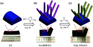
The fabrication process of CoS2 NTA/CC is schematically illustrated in Fig. 1. Firstly, wire-like cobalt-based MOF arrays (denoted as Co-MOF) are grown on carbon cloth by a modified solution method, which is based on our previous reports.53,54 Noting that the MOF arrays can be grown on different conductive substrates, here we just use carbon cloth as a typical flexible conductive support.53 In the second step, the Co-MOF was reacted with thioacetamide (TAA) in ethanol followed by a thermal treatment in N2, after which hollow CoS2 NTA with high crystallinity was obtained on carbon cloth, which can be directly used as a bifunctional electrocatalyst for overall water splitting.
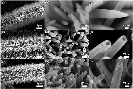
Scanning electron microscopy (SEM) images in Fig. 2a–c show that the Co-MOF nanoarrays are uniformly grown on the carbon cloth. The crystallinity of the Co-MOF nanoarrays is confirmed by the X-ray diffraction (XRD) study (see Fig. S1a, ESI†), from which the diffraction peaks indicate that the Co-MOF is of a layered phase that matches well with previously reported results and its composition can be determined to be Co(mim)2·(Hmim)1/2·(H2O)3/2 (C10H16N5O3/2Co).35,54,55 The energy-dispersive X-ray spectroscopy (EDX) spectrum of the Co-MOF nanoarrays (Fig. S1b, ESI†) confirms the existence of organic ligands containing N. Fig. 2d shows the typical morphology of Co-MOF after 3 h of reaction with TAA, from which one can see that the arrays still maintain uniform coverage on the carbon cloth. From the magnified images in Fig. 2e and f, nanotubes with inner pores can be clearly observed, indicating that hollow tubular structures have been formed. During the reaction between Co-MOF and TAA, the hydrolysis of TAA etches the Co-MOF to create a hollow structure and to promote the deposition of CoS2. This approach has been reported to be an efficient way to create a central pore space and deposit metal sulfides.56,57 The disappearance of the Co-MOF peaks from the XRD pattern (Fig. S1a, ESI†) and absence of the N signal in the EDX spectra (Fig. S1b, ESI†) indicate the successful etching of the Co-MOF nanoarray. It is worth mentioning that the reaction time has a huge impact on the formation of hollow structures. Wire-in-tube structures could be formed by an insufficient short-time reaction with TAA (Fig. S2, ESI†), while excess reaction time leads to the collapse of the Co-MOF arrays (Fig. S3, ESI†). After thermal treatment in N2, the crystallinity of the materials is enhanced, and the tubular arrays are well retained, as shown in Fig. 2g. From the magnified images in Fig. 2h and i, one can see that the surface of the nanotubes has become a little rough, indicating the formation of small nanocrystals.
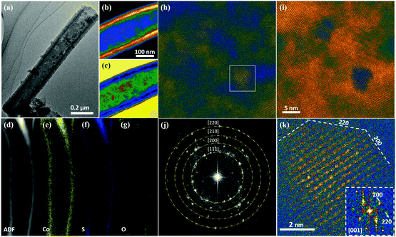
Characterization using transmission electron microscopy (TEM) has been conducted to show the structure change from the wire-like Co-MOF to tubular CoS2 nanoarrays. A typical Co-MOF nanowire is shown in Fig. S4a (ESI†), which has a solid feature with a diameter of ∼200 nm, corresponding well with the SEM study. After 3 h of reaction with TAA, hollow tubes can be clearly observed as shown in Fig. S4b (ES1†). From the magnified image in Fig. S4c (ES1†) it can be observed that a typical nanotube exhibits a wall thickness of ∼20 nm and the surface is smooth. After annealing in N2 (Fig. 3a), the nanotube structure is well preserved, and the surface becomes a little rough. In order to observe the detailed morphological and structural features of the nanotubes developed after annealing, scanning transmission electron microscopy (STEM) was employed. Fig. 3b and c show low-magnification colored STEM high angle annular dark field (HAADF) and annular bright field (ABF) images of a typical nanotube. STEM HAADF/ABF is known to be an effective structure imaging mode, producing contrast interpretable by mass-thickness (the signal is proportional to the number of atoms) or Z contrast (the signal is roughly proportional to Z). Additionally, STEM ABF is always contrast reversed to HAADF, and shows weaker Z-dependence.58–60 The morphology of the hollow tube is quite obviously shown by the contrast difference in the STEM-HAADF/ABF images. To detect the local chemical features of such a nanotube, we performed energy-dispersive X-ray spectroscopy (EDX) studies in STEM, as shown in Fig. 3d–g. The results clearly show a homogeneous elemental distribution of Co and S, while O is slightly enriched in the outer region of the nanotube due to some surface oxidation effect (Fig. 3g). To further study the local structure of the nanotube, atomic-resolution STEM HAADF/ABF studies were performed to uncover the structural features. Fig. 3h and i show colored STEM HAADF and ABF images with high magnification, focusing on the wall of the nanotube. Fig. 3j shows the fast Fourier transform (FFT) image obtained on the basis of Fig. 3i, from which the polycrystalline rings are well matched with the main planes ((111), (200), (210) and (220)) of CoS2 (JPCDS card no.: 41-1471). It is clear that the nanotube wall is polycrystalline with quite a small grain size (about 5–10 nm). Considering the nanotube width (about 20 nm), it is difficult to obtain clear crystal lattices due to the overlap of about 10 nanograins. As shown in Fig. S4d (ESI†), in most areas of the nanotube the lattice planes overlap, and the structure can be regarded as nanograins embedded in an amorphous matrix. Benefitting from the high resolution (around 80 pm) of aberration-corrected STEM, we can clearly see the lattice in individual nanograins, as shown in Fig. 3k. Such lattice spacings, of 0.28 nm (observed along the [001] zone axis), match well with the cubic crystalline structure of CoS2 (JPCDS card no.: 41-1471). Interestingly, the grain boundaries always align along a low-index orientation, e.g., [100] and [110] planes, as shown in Fig. 3k, which have a lower level of surface energy. The key structural feature of the CoS2 nanotube after annealing is the nanoscale grain structure with a high density of grain boundaries, which would contribute to many active sites for both HER and OER catalytic reactions.
XRD and X-ray photoelectron spectroscopy (XPS) measurements are further performed to study the CoS2 NTA/CC electrode, as shown in Fig. 4. From the XRD spectra shown in Fig. 4a, besides the signals from the carbon cloth support, all the diffraction peaks of the hollow nanoarrays can be well indexed to the CoS2 phase (JPCDS card no: 41-1471). From the XPS results in Fig. 4b, the broad scan of the CoS2 NTA/CC electrode shows C, Co, S, and O elements without any other impurities. The S 1s spectra shown in Fig. 4c can be well fitted with three sub-peaks: the peak located at 162.7 eV indicating the valence of −1 of S, and the peak at 168.6 eV is typical of surface sulfur oxides.61,62 The Co2p XPS spectra (Fig. 4d) show two identical peaks at 795.6 and 779.9 eV, corresponding to the Co 2p1/2 and Co 2p3/2 spin–orbit peaks of CoS2, respectively, which are in good agreement with previously reported results of CoS2 with certain surface oxidation.63–67
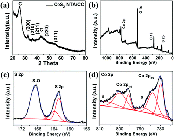 | ||
| Fig. 4 Characterization of the CoS2 NTA/CC electrode. (a) XRD spectra of CoS2 NTA/CC. (b) Broad scan, (c) S 2p spectra, and (d) Co 2p spectra of CoS2 NTA/CC. | ||
From the above discussion, it can be seen that tubular CoS2 nanoarrays directly grown on flexible carbon cloth have been successfully developed through a facile sulfidation process of a MOF precursor. The tubular CoS2 nanoarrays with sufficient open space are believed to facilitate the electrolyte penetration and promote the release of the evolved gas bubbles. Each single nanotube has the desired direct mechanical and electrical contact with the flexible carbon support, which enhances the mass and electron transfer and ensures proper flexibility of the electrode.
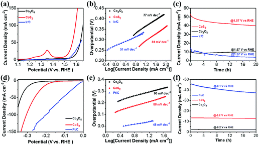
To verify the bifunctional catalytic properties of the CoS2 NTA for overall water splitting, electrochemical measurements were first performed in a 1 M KOH solution using a three-electrode configuration. The CoS2 NTA on carbon cloth was directly used as the working electrode, with a Pt plate as the counter electrode and SCE as the reference electrode. For comparison, samples of Co3O4 nanowire arrays assembled on carbon cloth, obtained by oxidation (without sulfidation) of Co-MOF (denoted as Co3O4 NWA/CC, Fig. S5, ESI†), and noble-metal based catalysts coated on carbon cloth with similar weight (Pt/C/CC and Ir/C/CC) were also tested. Fig. 5a shows the polarization curves of the catalysts in the OER test. The CoS2 NTA/CC electrode displays a small onset potential of 1.49 V (vs. RHE), while the onset potential for Co3O4 NWA/CC is 1.54 V (vs. RHE). In addition, the CoS2 NTA/CC electrode shows a small overpotential requirement of 276 mV to achieve a current density of 10 mA cm−2, while the Co3O4 NWA/CC electrode required a relatively large overpotential of 350 mV. Note that the anodic peaks between 1.2 and 1.5 V (vs. RHE) are formed as a result of the reaction of CoS2 and Co3O4 with OH− in the electrolyte. The improved activity of the CoS2 NTA/CC electrode can be due to the hollow structure with intrinsic sulfur doping. To investigate the electrochemically active surface areas for both CoS2 NTA/CC and Co3O4 NWA/CC electrodes, the electrochemical double-layer capacitances (Cdl) were calculated based on the cyclic voltammetry (CV) curves in an appropriate potential range without redox reactions (Fig. S6, ESI†). The CoS2 NTA/CC electrode has a much larger Cdl (612.6 mF cm−2) than the Co3O4 NWA/CC electrode (12.0 mF cm−2), suggesting its higher electrochemically active surface area for an efficient electrochemical reaction. The better electrochemical activity of the CoS2 NTA/CC electrode can also be observed from the electrochemical impedance spectroscopy (EIS) results (Fig. S6e, ESI†). From the Nyquist plots, the intercept of the X axis for the CoS2 NTA/CC electrode is smaller than that for the Co3O4 NWA/CC electrode in the high-frequency region, indicating smaller bulk resistance. The charge transfer resistance and the ionic diffusion resistance for the CoS2 NTA/CC electrode are also smaller than those of the Co3O4 NWA/CC electrode, as revealed by the smaller radius of the semicircle and the more vertical line in the low-frequency region, respectively. The Tafel slopes for all catalysts are shown in Fig. 5b, the CoS2 NTA/CC electrode illustrates a Tafel slope of 81 mV dec−1, which is close to that of the Co3O4 NWA/CC electrode (77 mV dec−1). Although the CoS2 NTA/CC electrode shows a much larger Tafel slope than the state-of-the-art Ir/C/CC electrode (51 mV dec−1), the onset potential for the CoS2 NTA/CC electrode is only 10 mV higher than that for Ir/C/CC. In addition, the Ir/C/CC requires a higher overpotential (329 mV) than the CoS2 NTA/CC electrode (276 mV) for achieving a current density of 10 mA cm−2, showing the comparable OER properties of the CoS2 NTA/CC electrode. The OER performance of the CoS2 NTA/CC electrode is also comparable to that of the recently reported non-noble metal based catalysts41,68–70 (Table S1, ESI†). Fig. 5c further compares the long-term electrochemical stability of the electrodes. At a constant voltage of 1.57 V (vs. RHE), the current density of Ir/C/CC deteriorates faster during the test, while the CoS2 NTA/CC electrode delivered a relatively stable current density during 20 h with slow degradation. The gradually decreased current of the CoS2 NTA/CC electrode can be due to the loss of S and the production of metal hydroxide, which is common for metal sulfide materials under alkaline conditions.41 Nevertheless, the CoS2 NTA/CC electrode demonstrated a much more stable OER performance than Ir/C/CC.
The catalytic performance of the electrodes for the HER is also tested with a carbon plate as the counter electrode and SCE as the reference electrode in the same electrolyte. From the polarization curves in Fig. 5d, the CoS2 NTA/CC electrode exhibits an onset potential of 120 mV and a small overpotential of 193 mV to reach 10 mA cm−2, which are lower than those for the Co3O4 NWA/CC electrode (onset potentials of 201 mV and 278 mV to achieve 10 mA cm−2). Fig. 5e presents the Tafel plots of the electrodes, from which one can see that the CoS2 NTA/CC electrode exhibits a Tafel slope of 88 mV dec−1, which is smaller than that of the Co3O4 NWA/CC electrode (90 mV dec−1). Since the slope falls within the range of 40–120 mV dec−1, the HER process on the CoS2 NTA/CC electrode could be categorized as the Volmer–Heyrovsky mechanism.44 Although the values from CoS2 NTA/CC electrodes are still worse than those from the Pt/C/CC electrode (which only requires an overpotential of 27 mV to deliver a current density of 10 mA cm−2, with a small Tafel slope of 48 mV dec−1), the CoS2 NTA/CC catalyst shows comparable properties to many other reported results from non-precious HER catalysts in an alkaline electrolyte41,45,70–73 (Table S2, ESI†). The long-term stability of the catalysts in the HER is further evaluated. As shown in Fig. 5f, both CoS2 NTA/CC and Co3O4 NWA/CC electrodes are shown to exhibit stable HER catalytic performance with negligible degradation in the current density over 20 h, which is much better than that of the Pt/C/CC electrode.
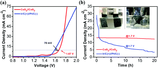
From the above discussion, the CoS2 NTA/CC electrode has been demonstrated to be an efficient stable bifunctional catalyst for both HER and OER reactions in alkaline media. The good catalytic properties can be attributed to the unique tubular structures with well-defined connection to the substrate, which provides rich reaction sites and promotes electron transfer. To demonstrate its potential for real applications, an alkaline electrolyzer using the CoS2 NTA/CC catalyst as both the anode and the cathode was assembled. A catalytic current of 10 mA cm−2 was achieved with a potential of 1.67 V (Fig. 6a), which compares favorably with the reported values from recent studies of bifunctional catalysts23,41,44,70,72 (Table S3, ESI†). Although the benchmarking Ir/C(+)//Pt/C(−) shows a small potential value of 1.6 V to achieve a current density of 10 mA cm−2, its current was surpassed by CoS2//CoS2 at a higher voltage. In addition, the stability of the Ir/C(+)//Pt/C(−) cell is very poor, dropping fast in the first few hours and only maintaining ∼3.4 mA cm−2 after 20 h (Fig. 6b). The CoS2 NTA/CC based electrolyzer, on the other hand, shows much better stability, as shown in Fig. 6b. To prove the potential usage in integrated multi-functional flexible electronics, the stability and flexibility of CoS2//CoS2 was tested within the first 10 h in a flat state and the last 10 h in a bent state. At a constant voltage of 1.7 V, the electrolyzer can maintain a stable current density of ∼13 mA cm−2 for the 20 h test, showing a promisingly high electrochemical stability and excellent structure flexibility. The stability was further illustrated by a post-mortem study (Fig. S7, ESI†), from which the one-dimensional arrays for both electrodes can be well maintained after the stability test. The low overpotential and high electrochemical stability together with the flexibility demonstrate great promise for practical applications of CoS2 NTA/CC catalysts in full water splitting and potential integrated flexible electronics.
Conclusions
In summary, hollow CoS2 tubular arrays assembled on carbon cloth have been rationally designed and successfully constructed by a cost-effective sulfidation process from a MOF precursor. The CoS2 NTA with an open pore space and numerous nanoscale grains provides a high density of active sites and enhanced release of generated gases, and the well-defined connection of each single nanotube to the substrate ensures improved electron transport and high mechanical stability. Through electrochemical evaluation, we observed that the CoS2 NTA demonstrates remarkable bifunctional catalytic properties for both HER and OER reactions. An alkaline electrolyzer using the CoS2 NTA/CC catalyst as both the anode and the cathode can realize a catalytic current of 10 mA cm−2 with a potential of 1.67 V. Highly desired electrochemical stability and flexibility have also been demonstrated. Such MOF derived hollow nanoarrays with high electrochemical performance pave the way for the rational design and fabrication of multi-functional hierarchical nanostructures for efficient energy conversion and storage.Acknowledgements
The authors acknowledge the support of MOE and NUS. This work was supported by MOE (MOE2015-T2-2-094), conducted at the National University of Singapore.Notes and references
- H. Wang, S. Xu, C. Tsai, Y. Li, C. Liu, J. Zhao, Y. Liu, H. Yuan, F. Abild-Pedersen, F. B. Prinz, J. K. Nørskov and Y. Cui, Science, 2016, 354, 1031–1036 CrossRef CAS PubMed.
- X. Huang, Z. Zhao, L. Cao, Y. Chen, E. Zhu, Z. Lin, M. Li, A. Yan, A. Zettl, Y. M. Wang, X. Duan, T. Mueller and Y. Huang, Science, 2015, 348, 1230–1234 CrossRef CAS PubMed.
- H. Chen and S. Yang, Nanoscale Horiz., 2016, 1, 96–108 RSC.
- M. G. Walter, E. L. Warren, J. R. McKone, S. W. Boettcher, Q. Mi, E. A. Santori and N. S. Lewis, Chem. Rev., 2010, 110, 6446–6473 CrossRef CAS PubMed.
- W. Liu, E. Hu, H. Jiang, Y. Xiang, Z. Weng, M. Li, Q. Fan, X. Yu, E. I. Altman and H. Wang, Nat. Commun., 2016, 7, 10771 CrossRef CAS PubMed.
- J. Zhang, Z. Zhao, Z. Xia and L. Dai, Nat. Nanotechnol., 2015, 10, 444–452 CrossRef CAS PubMed.
- Y. Sun, C. Liu, D. C. Grauer, J. Yano, J. R. Long, P. Yang and C. J. Chang, J. Am. Chem. Soc., 2013, 135, 17699–17702 CrossRef CAS PubMed.
- H. Yin, S. Zhao, K. Zhao, A. Muqsit, H. Tang, L. Chang, H. Zhao, Y. Gao and Z. Tang, Nat. Commun., 2015, 6, 6430 CrossRef CAS PubMed.
- J. Wang, W. Cui, Q. Liu, Z. Xing, A. M. Asiri and X. Sun, Adv. Mater., 2016, 28, 215–230 CrossRef CAS PubMed.
- P. Xiao, W. Chen and X. Wang, Adv. Energy Mater., 2015, 5, 1500985 CrossRef.
- M. Caban-Acevedo, M. L. Stone, J. R. Schmidt, J. G. Thomas, Q. Ding, H.-C. Chang, M.-L. Tsai, J.-H. He and S. Jin, Nat. Mater., 2015, 14, 1245–1251 CrossRef CAS PubMed.
- Y. Hou, Z. Wen, S. Cui, S. Ci, S. Mao and J. Chen, Adv. Funct. Mater., 2015, 25, 872–882 CrossRef CAS.
- T. R. Hellstern, J. D. Benck, J. Kibsgaard, C. Hahn and T. F. Jaramillo, Adv. Energy Mater., 2016, 6, 1501758 CrossRef.
- Y.-J. Tang, Y. Wang, X.-L. Wang, S.-L. Li, W. Huang, L.-Z. Dong, C.-H. Liu, Y.-F. Li and Y.-Q. Lan, Adv. Energy Mater., 2016, 6, 1600116 CrossRef.
- J.-X. Feng, L.-X. Ding, S.-H. Ye, X.-J. He, H. Xu, Y.-X. Tong and G.-R. Li, Adv. Mater., 2015, 27, 7051–7057 CrossRef CAS PubMed.
- H. Jin, J. Wang, D. Su, Z. Wei, Z. Pang and Y. Wang, J. Am. Chem. Soc., 2015, 137, 2688–2694 CrossRef CAS PubMed.
- J. Zhang, T. Wang, D. Pohl, B. Rellinghaus, R. Dong, S. Liu, X. Zhuang and X. Feng, Angew. Chem., 2016, 128, 6814–6819 CrossRef.
- P. Chen, T. Zhou, L. Xing, K. Xu, Y. Tong, H. Xie, L. Zhang, W. Yan, W. Chu, C. Wu and Y. Xie, Angew. Chem., Int. Ed., 2016, 56, 610–614 CrossRef PubMed.
- X. Jia, Y. Zhao, G. Chen, L. Shang, R. Shi, X. Kang, G. I. N. Waterhouse, L.-Z. Wu, C.-H. Tung and T. Zhang, Adv. Energy Mater., 2016, 6, 1502585 CrossRef.
- G. Zhang, Z.-A. Lan, L. Lin, S. Lin and X. Wang, Chem. Sci., 2016, 7, 3062–3066 RSC.
- M. Kuang and G. Zheng, Small, 2016, 12, 5656–5675 CrossRef CAS PubMed.
- X. Wang, W. Li, D. Xiong, D. Y. Petrovykh and L. Liu, Adv. Funct. Mater., 2016, 26, 4067–4077 CrossRef CAS.
- X. Gao, H. Zhang, Q. Li, X. Yu, Z. Hong, X. Zhang, C. Liang and Z. Lin, Angew. Chem., Int. Ed., 2016, 55, 6290–6294 CrossRef CAS PubMed.
- Y. Hou, M. R. Lohe, J. Zhang, S. Liu, X. Zhuang and X. Feng, Energy Environ. Sci., 2016, 9, 478–483 CAS.
- L. Jiao, Y.-X. Zhou and H.-L. Jiang, Chem. Sci., 2016, 7, 1690–1695 RSC.
- Y. Zhu, W. Zhou, Y. Zhong, Y. Bu, X. Chen, Q. Zhong, M. Liu and Z. Shao, Adv. Energy Mater., 2016, 7, 1602122 CrossRef.
- W. Fang, D. Liu, Q. Lu, X. Sun and A. M. Asiri, Electrochem. Commun., 2016, 63, 60–64 CrossRef CAS.
- B. Y. Xia, Y. Yan, N. Li, H. B. Wu, X. W. Lou and X. Wang, Nat. Energy, 2016, 1, 15006 CrossRef CAS.
- I. Hod, P. Deria, W. Bury, J. E. Mondloch, C.-W. Kung, M. So, M. D. Sampson, A. W. Peters, C. P. Kubiak, O. K. Farha and J. T. Hupp, Nat. Commun., 2015, 6, 8304 CrossRef CAS PubMed.
- A. Mahmood, W. Guo, H. Tabassum and R. Zou, Adv. Energy Mater., 2016, 6, 1600423 CrossRef.
- J. Lee, O. K. Farha, J. Roberts, K. A. Scheidt, S. T. Nguyen and J. T. Hupp, Chem. Soc. Rev., 2009, 38, 1450–1459 RSC.
- J. Zhou, Y. Dou, A. Zhou, R.-M. Guo, M.-J. Zhao and J.-R. Li, Adv. Energy Mater., 2017, 6, 1602643 CrossRef.
- S. Zhao, H. Yin, L. Du, L. He, K. Zhao, L. Chang, G. Yin, H. Zhao, S. Liu and Z. Tang, ACS Nano, 2014, 8, 12660–12668 CrossRef CAS PubMed.
- S. Zhao, Y. Wang, J. Dong, C.-T. He, H. Yin, P. An, K. Zhao, X. Zhang, C. Gao, L. Zhang, J. Lv, J. Wang, J. Zhang, A. M. Khattak, N. A. Khan, Z. Wei, J. Zhang, S. Liu, H. Zhao and Z. Tang, Nat. Energy, 2016, 1, 16184 CrossRef CAS.
- R. Chen, J. Yao, Q. Gu, S. Smeets, C. Baerlocher, H. Gu, D. Zhu, W. Morris, O. M. Yaghi and H. Wang, Chem. Commun., 2013, 49, 9500–9502 RSC.
- J. Xu, S. Cao, T. Brenner, X. Yang, J. Yu, M. Antonietti and M. Shalom, Adv. Funct. Mater., 2015, 25, 6265–6271 CrossRef CAS.
- M. Shalom, S. Inal, C. Fettkenhauer, D. Neher and M. Antonietti, J. Am. Chem. Soc., 2013, 135, 7118–7121 CrossRef CAS PubMed.
- R. S. Sprick, B. Bonillo, R. Clowes, P. Guiglion, N. J. Brownbill, B. J. Slater, F. Blanc, M. A. Zwijnenburg, D. J. Adams and A. I. Cooper, Angew. Chem., Int. Ed., 2016, 55, 1792–1796 CrossRef CAS PubMed.
- B. Y. Guan, L. Yu and X. W. Lou, Angew. Chem., Int. Ed., 2017, 56, 2386–2389 CrossRef CAS PubMed.
- B. You, N. Jiang, M. Sheng, S. Gul, J. Yano and Y. Sun, Chem. Mater., 2015, 27, 7636–7642 CrossRef CAS.
- J. Wang, H.-X. Zhong, Z.-L. Wang, F.-L. Meng and X.-B. Zhang, ACS Nano, 2016, 10, 2342–2348 CrossRef CAS PubMed.
- H. Liang, A. N. Gandi, D. H. Anjum, X. Wang, U. Schwingenschlögl and H. N. Alshareef, Nano Lett., 2016, 16, 7718–7725 CrossRef CAS PubMed.
- T. Ling, D.-Y. Yan, Y. Jiao, H. Wang, Y. Zheng, X. Zheng, J. Mao, X.-W. Du, Z. Hu, M. Jaroniec and S.-Z. Qiao, Nat. Commun., 2016, 7, 12876 CrossRef CAS PubMed.
- G.-F. Chen, T. Y. Ma, Z.-Q. Liu, N. Li, Y.-Z. Su, K. Davey and S.-Z. Qiao, Adv. Funct. Mater., 2016, 26, 3314–3323 CrossRef CAS.
- J. Tian, Q. Liu, A. M. Asiri and X. Sun, J. Am. Chem. Soc., 2014, 136, 7587–7590 CrossRef CAS PubMed.
- C. Guan, X. Qian, X. Wang, Y. Cao, Q. Zhang, A. Li and J. Wang, Nanotechnology, 2015, 26, 094001 CrossRef CAS PubMed.
- C. Guan, W. Zhao, Y. Hu, Q. Ke, X. Li, H. Zhang and J. Wang, Adv. Energy Mater., 2016, 6, 1601034 CrossRef.
- C. Guan and J. Wang, Adv. Sci., 2016, 3, 1500405 CrossRef PubMed.
- P. Xiong, J. Zhu, L. Zhang and X. Wang, Nanoscale Horiz., 2016, 1, 340–374 RSC.
- R. Li, Z. Lin, X. Ba, Y. Li, R. Ding and J. Liu, Nanoscale Horiz., 2016, 1, 150–155 RSC.
- F. Wang, X. Wang, Z. Chang, Y. Zhu, L. Fu, X. Liu and Y. Wu, Nanoscale Horiz., 2016, 1, 272–289 RSC.
- T. Zhai, X. Lu, F. Wang, H. Xia and Y. Tong, Nanoscale Horiz., 2016, 1, 109–124 RSC.
- C. Guan, W. Zhao, Y. Hu, Z. Lai, X. Li, S. Sun, H. Zhang, A. K. Cheetham and J. Wang, Nanoscale Horiz., 2017, 2, 99–105 RSC.
- C. Guan, X. Liu, W. Ren, X. Li, C. Cheng and J. Wang, Adv. Energy Mater., 2017, 7, 1602391 CrossRef.
- G. Fang, J. Zhou, C. Liang, A. Pan, C. Zhang, Y. Tang, X. Tan, J. Liu and S. Liang, Nano Energy, 2016, 26, 57–65 CrossRef CAS.
- Z. Jiang, W. Lu, Z. Li, K. H. Ho, X. Li, X. Jiao and D. Chen, J. Mater. Chem. A, 2014, 2, 8603–8606 CAS.
- H. Hu, L. Han, M. Yu, Z. Wang and X. W. Lou, Energy Environ. Sci., 2016, 9, 107–111 CAS.
- S. J. Pennycook and L. A. Boatner, Nature, 1988, 336, 565–567 CrossRef CAS.
- H. Wu, F. Zheng, D. Wu, Z.-H. Ge, X. Liu and J. He, Nano Energy, 2015, 13, 626–650 CrossRef CAS.
- S. J. Pennycook, Ultramicroscopy, 1989, 30, 58–69 CrossRef.
- M. S. Faber, R. Dziedzic, M. A. Lukowski, N. S. Kaiser, Q. Ding and S. Jin, J. Am. Chem. Soc., 2014, 136, 10053–10061 CrossRef CAS PubMed.
- R. B. Pujari, A. C. Lokhande, J. H. Kim and C. D. Lokhande, RSC Adv., 2016, 6, 40593–40601 RSC.
- W. Qiu, J. Jiao, J. Xia, H. Zhong and L. Chen, Chem. – Eur. J., 2015, 21, 4359–4367 CrossRef CAS PubMed.
- J. Xie, S. Liu, G. Cao, T. Zhu and X. Zhao, Nano Energy, 2013, 2, 49–56 CrossRef CAS.
- S. Peng, L. Li, S. G. Mhaisalkar, M. Srinivasan, S. Ramakrishna and Q. Yan, ChemSusChem, 2014, 7, 2212–2220 CrossRef CAS PubMed.
- G. Zhang, S. Zang and X. Wang, ACS Catal., 2015, 5, 941–947 CrossRef CAS.
- M.-R. Gao, X. Cao, Q. Gao, Y.-F. Xu, Y.-R. Zheng, J. Jiang and S.-H. Yu, ACS Nano, 2014, 8, 3970–3978 CrossRef CAS PubMed.
- H. Liang, F. Meng, M. Cabán-Acevedo, L. Li, A. Forticaux, L. Xiu, Z. Wang and S. Jin, Nano Lett., 2015, 15, 1421–1427 CrossRef CAS PubMed.
- T. Y. Ma, S. Dai, M. Jaroniec and S. Z. Qiao, J. Am. Chem. Soc., 2014, 136, 13925–13931 CrossRef CAS PubMed.
- Y. P. Zhu, T. Y. Ma, M. Jaroniec and S. Z. Qiao, Angew. Chem., Int. Ed., 2016, 56, 1324–1328 CrossRef PubMed.
- Z.-H. Xue, H. Su, Q.-Y. Yu, B. Zhang, H.-H. Wang, X.-H. Li and J.-S. Chen, Adv. Energy Mater., 2017, 7, 1602355 CrossRef.
- J. Luo, J.-H. Im, M. T. Mayer, M. Schreier, M. K. Nazeeruddin, N.-G. Park, S. D. Tilley, H. J. Fan and M. Grätzel, Science, 2014, 345, 1593–1596 CrossRef CAS PubMed.
- Y. Liang, Q. Liu, A. M. Asiri, X. Sun and Y. Luo, ACS Catal., 2014, 4, 4065–4069 CrossRef CAS.
Footnote |
| † Electronic supplementary information (ESI) available: Additional SEM, TEM, XRD and EDX results of the wire-like Co–MOF arrays on carbon cloth with different reaction times with TAA, SEM and TEM images of Co3O4 nanowires on carbon cloth, CV, plot of current density vs. scan rates, and Nyquist plots of CoS2 NTA and Co3O4 NWA, SEM images of CoS2 NTA/CC after the test in OER and HER, Table S1. Summary of recently reported highly active OER catalysts in a 1 M KOH or NaOH electrolyte, Table S2. Summary of recently reported highly active HER catalysts in a 1 M KOH electrolyte, and Table S3. Summary of recently reported representations of highly active bifunctional catalysts for overall water-splitting. See DOI: 10.1039/c7nh00079k |
| This journal is © The Royal Society of Chemistry 2017 |

