A dual solvent evaporation route for preserving carbon nanoparticle fluorescence in silica gel and producing white light-emitting diodes†
Yan
Cui
a,
Xinyuan
Bu
b,
Haoyang
Zou
b,
Xiaowei
Xu
a,
Ding
Zhou
b,
Huiwen
Liu
b,
Xun
Zhang
c,
Yi
Liu
b,
Hongchen
Sun
*a,
Jinlan
Jiang
*d and
Hao
Zhang
*b
aSchool of Stomatology, Jilin University, Changchun 130041, P. R. China. E-mail: hcsun@mail.jlu.edu.cn
bState Key Laboratory of Supramolecular Structure and Materials, College of Chemistry, Jilin University, Changchun 130012, P. R. China. E-mail: hao_zhang@jlu.edu.cn
cJilin Entry-Exit Inspection and Quarantine Bureau, Changchun 130062, P. R. China
dScientific Research Center, China-Japan Union Hospital of Jilin University, Changchun 130033, P. R. China. E-mail: jiangjl2003@hotmail.com
First published on 16th August 2016
Abstract
Carbon nanoparticles (C-NPs) are novel and competitive luminescent materials both in academic research and practical applications owing to their environment-friendly behavior and high abundance on Earth. Despite the successes in preparing strongly luminescent C-NPs, preserving the luminescence in solid materials is still challenging. With the aim to produce C-NP-based white-light-emitting diodes (WLEDs), in this work, solvent-dispersible C-NPs are embedded into commercial silica gel via a dual solvent evaporation route. The basic idea is to lower the evaporation rate of the solvents, thus leading to a good dispersion of the C-NPs in the silica gel. This method avoids the aggregation-induced emission quenching of C-NPs in solid materials, and therefore preserves the strong luminescence in the C-NPs/silica gel composites. The composites are further blended with polydimethylsiloxane and act as the color conversion layer on InGaN UV-blue emitting chips, which produces LEDs with a bright white emission.
1. Introduction
Carbon nanoparticles (C-NPs) are one of the most fascinating carbon-based materials in current nanoresearch and are defined as quasi-spherical graphitic particles with diameters below 10 nm.1,2 As competitive candidates to traditional semiconductor quantum dots (Q-dots), C-NPs exhibit the advantages of being inexpensive, can be synthesized on a large-scale, the surfaces can be decorated easily, and, in particular, having an intrinsic low toxicity from the bio-friendly carbon composition.3–5 They are strongly expected to have applications in energy conversion, catalysis, sensors, and bioassays. The synthetic techniques of solution-processed C-NPs have been rapidly improving in the past half decade.6–12 C-NPs can be synthesized through top-down and bottom-up routes with specific sizes and surface functionalities, as well as having tunable fluorescent colors and high quantum yields.13–16 However, the design and fabrication of C-NP-based photoelectric devices is still challenging because of the poor dispersibility and, subsequently, the serious fluorescence quenching of C-NPs in solid state materials.One promising application of C-NPs is white-light-emitting diodes (WLEDs) due to the huge market demand of low cost backlights in liquid crystal displays, full color displays, and next generation lighting sources.17–24 However, the few examples of C-NP WLEDs are concealed by the numerous reports concerning inorganic WLEDs, all-organic WLEDs, and Q-dot WLEDs.25,26 This is mainly attributed to the difficulty in synthesizing white-light-emitting C-NPs and, in particular, avoiding the fluorescence quenching in solid state devices. Typically, the emitted light can be generated from the LEDs in two different ways. One is the direct use of emitting materials as the emissive layer, which requires precise device structural optimization and processing.17–20 The other structure employs a UV-blue emitting chip as the light source and the emitting material as the color conversion layer.21–24 The second type avoids the direct carrier injection, and therefore increases the stability of the color conversion layer.21 In addition, the technique for processing the color conversion layer is much simpler in comparison to the emissive layer.21 So, this type of WLEDs with C-NPs has the highest potential in practical applications, just like commercial inorganic WLEDs. The key to achieving efficient WLEDs is how to preserve the C-NP fluorescence in the color conversion layer. Despite the strong emission of C-NP solutions, the emission intensity of dried C-NPs is very low because of aggregation. Embedding the C-NPs in an inert media is considered to solve this problem. For example, hybrids of C-NPs with polymers and silica have been demonstrated to maintain fluorescence.27–32 However, the emission intensity of C-NP-embedded silica is still at a low level. To employ the state-of-the-art synthesis of C-NPs to generate practical WLEDs, effective methods for preserving the C-NP fluorescence in solid materials are greatly needed. It is known that the aggregation of NPs depends on the evaporation rate of solvents, which has been employed to tune the performance of NPs.33 Consequently, the emission intensity of C-NPs composites can potentially be enhanced by using mixed solvents to control the evaporation behavior.
In this work, highly luminescent C-NPs are prepared in aqueous media using P2O5 to oxidize acetic acid. The as-prepared C-NPs are extracted into ethyl acetate and subsequently combined with commercial silica gel for producing LEDs. To preserve the strong luminescence in the C-NPs/silica gel composites, before solvent evaporation CCl4 is added into the C-NP solution to generate an ethyl acetate/CCl4 binary solvent system. Such a system lowers the evaporation rate of the solvents, leading to a good dispersibility of the C-NPs in the silica gel. Consequently, strong luminescence is preserved. The C-NPs/silica gel composites are mixed with polydimethylsiloxane (PDMS), and subsequently coated on an InGaN UV-blue emitting chip as a color conversion layer. The resultant devices show bright white emission.
2. Experiment
2.1 Materials
Phosphorus pentoxide (P2O5), acetic acid (CH3COOH), ethyl acetate (AR), CCl4 (AR), acetone (AR), CHCl3 (AR), alcohol (C2H5OH, AR), and silica gel were all commercially available products and used as received without further purification. Polydimethylsiloxane (PDMS) elastomer kits (Sylgard 184) were purchased from Dow Corning (Midland, MI).2.2 Preparation of C-NPs
C-NPs were prepared according to a previous method.34 0.8 mL acetic acid was diluted with 0.2 mL water, and rapidly put into a 10 mL beaker containing 2.5 g P2O5. The mixture was cooled down to room temperature under ambient conditions. The products were dissolved into 10 mL water, and extracted using 15 mL ethyl acetate. The resulting C-NPs ethyl acetate solution with a bright yellow-green emission was stored in a conical flask for further applications.2.3 Preparation of C-NPs/silica gel composites
0.8 g silica gel with diameter of 20–30 nm was placed into a 5 mL beaker. Subsequently, 2 mL C-NPs ethyl acetate solution and 2 mL CCl4 were added under stirring. The solvents were evaporated at 45 °C to achieve the powder of C-NPs/silica gel composites. For studying the influence of C-NPs concentration, seven 0.8 g portions of silica gel were respectively mixed with 0.5 mL C-NPs solution and 3.5 mL CCl4, 1.0 mL C-NPs solution and 3.0 mL CCl4, 1.5 mL C-NPs solution and 2.5 mL CCl4, 2.0 mL C-NPs solution and 2.0 mL CCl4, 2.5 mL C-NPs solution and 1.5 mL CCl4, 3.0 mL C-NPs solution and 1.0 mL CCl4, 3.5 mL C-NPs solution and 0.5 mL CCl4, and followed by evaporating at 45 °C to produce the composites. To reveal the effect of the solvents, five 0.8 g portions of silica gel were respectively mixed with 2.0 mL C-NPs solution. Subsequently, the mixtures were respectively mixed with 2.0 mL ethyl acetate, 2.0 mL CCl4, 2.0 mL acetone, 2.0 mL CHCl3, and 2.0 mL alcohol. After evaporating the solvent at 45 °C, the composites were produced.2.4 Fabrication of the WLEDs
InGaN LED chips without a phosphor coating were purchased from Shen Zhen Hongcai Elecronics Co., Ltd. The emission of the LED chip was centered at 450 nm, and the operating voltage was 3.0 V. A C-NPs/silica gel composite powder was mixed with the PDMS precursors with a specific ratio. The mixtures were put in a vacuum chamber to remove bubbles. Subsequently, the mixtures were use to fill the cup-shaped voids of the LED chips. After curing at 80 °C for 3 h, WLEDs from the C-NPs/silica gel composites were fabricated.2.5 Characterization
UV-visible absorption spectra were obtained using a Lambda 800 UV-vis spectrophotometer. Photoluminescence (PL) spectroscopy was performed with a Shimadzu RF-5301 PC spectrophotometer. The excitation wavelength was 450 nm. The absolute quantum yields were measured on an Edinburgh FLS920 equipped with an integrating sphere. Transmission electron microscopy (TEM) was conducted using a Hitachi H-800 electron microscope at an acceleration voltage of 200 kV with a CCD camera. Fourier transform infrared (FTIR) spectra were performed with a Nicolet AVATAR 360 FTIR instrument. X-ray photoelectron spectroscopy (XPS) was investigated using a VG ESCALAB MKII spectrometer with a Mg KR excitation (1253.6 eV). Binding energy calibration was based on C 1s at 284.6 eV. The color of light was identified by the CIE (Commission Internationale de L'Eclairage 1931) colorimetry system. Any color could be described by the chromaticity (x, y) coordinates on the CIE diagram.3. Result and discussion
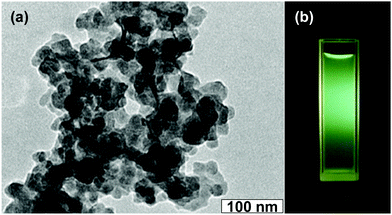
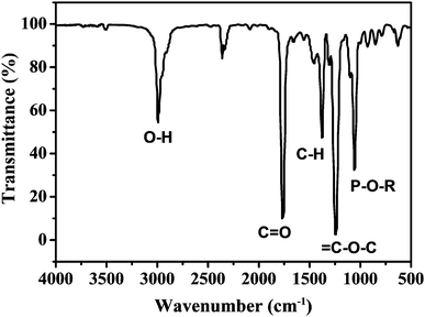
As mentioned in the Experimental section, C-NPs are foremost prepared in aqueous media using P2O5 to oxidize acetic acid according to the previous method.34Fig. 1a shows a transmission electron microscopy (TEM) image of the products, which appear as spherical particles with a diameter around 25–30 nm. In aqueous media, the particles further form bigger aggregates around 200–300 nm, implying that despite the products being dispersible in water, the water-dispersibility is not good. After being extracted to ethyl acetate (Experimental section), the products exhibit a strong yellow-green emission (Fig. 1b). Such materials could potentially be combined with a commercial InGaN UV-blue emitting chip and act as a color conversion layer for fabricating WLEDs.35–38The composition of the products was further studied by Fourier transform infrared (FTIR) and X-ray photoelectron spectroscopy (XPS). FTIR presents strong peaks around 3000, 1750, 1370, 1250, and 1100 cm−1, which correspond to the characteristic absorptions of O–H, C![[double bond, length as m-dash]](https://www.rsc.org/images/entities/char_e001.gif) O, C–H, C–O–C, and P–O–R (Fig. 2). The presence of these hydrophilic groups explains why the products are dispersible in water and ethyl acetate. Fig. 3 presents the XPS O 1s, P 2p, and C 1s spectra. The strong XPS peaks indicate that the products are composed of C, O, and P elements. In the O 1s spectrum, both carboxylate O and phosphate O are found. In the C 1s spectrum, C presents three forms. Most of the C is in the form of elemental carbon, while a small amount of C is in the form of ether and carboxylate. On the basis of XPS quantitative analysis (Table 1), the composition of the products is determined as (C6O3P)n, which a C-based material.
O, C–H, C–O–C, and P–O–R (Fig. 2). The presence of these hydrophilic groups explains why the products are dispersible in water and ethyl acetate. Fig. 3 presents the XPS O 1s, P 2p, and C 1s spectra. The strong XPS peaks indicate that the products are composed of C, O, and P elements. In the O 1s spectrum, both carboxylate O and phosphate O are found. In the C 1s spectrum, C presents three forms. Most of the C is in the form of elemental carbon, while a small amount of C is in the form of ether and carboxylate. On the basis of XPS quantitative analysis (Table 1), the composition of the products is determined as (C6O3P)n, which a C-based material.
| C | O | P | |
|---|---|---|---|
| Content (%) | 57.5 | 30.7 | 11.8 |
In this study, the C and O elements originate from the acetic acid raw material, while the P element originates from the oxidant of P2O5. Despite the reaction between acetic acid and P2O5 being too complex to write a specific equation, the products should be crosslinked because both acetic acid and P2O5 possess multiple sites for the oxidation reaction. By further combining the morphology and the large size of the products under TEM, the as-prepared C-NPs are considered to have a polymer-like structure, and can also be defined as polymer dots according to previous reports.39,40 For better comprehension, the products are termed as C-NPs in the following statements.
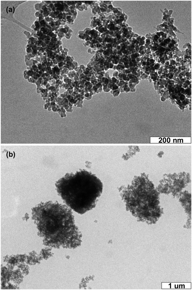
One of the keys for fabricating C-NPs-based LEDs is the preservation of C-NP fluorescence in the color conversion layer after coating on a commercial InGaN chip. Despite the C-NP solution exhibiting a strong emission, the emission intensity of dried C-NPs will greatly decrease. In order to preserve the strong emission, C-NPs are further combined with commercial silica gel. The silica gel can be well dispersed in a variety of polar solvents, such as ethyl acetate, CCl4, CHCl3, acetone, and alcohol. The TEM image indicates that the size of the silica particles is around 20–30 nm (Fig. 4a). In fabricating the composites, suspensions of C-NPs and silica gel are directly mixed. C-NPs are able to adsorb on the surface of the silica gel, producing composites with a size of around 1000 nm (Fig. 4b). Despite the big size, the composites can still be dispersed in solution.
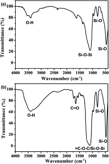
In order to confirm the coexistence of C-NPs and silica gel, as well as their interaction in forming composites, the composites are characterized by FTIR spectra (Fig. 5). For the spectrum of the silica gel, strong peaks around 3500, 1100, 750, and 500 cm−1 are observed, which correspond to the characteristic silica absorptions of O–H, Si–O–Si, and Si–O (Fig. 5a). In the composites, the strong characteristic peaks of the silica remain, while the C![[double bond, length as m-dash]](https://www.rsc.org/images/entities/char_e001.gif) O characteristic peak around 1750 cm−1 for the C-NPs is also found (Fig. 2 and 5b). This means that the composites are composed of C-NPs and silica gel. In addition, the FTIR spectrum indicates that the surface group of silica gel is –OH (Fig. 5a), while the C-NPs possess –COOH (Fig. 2). Because –OH and –COOH have strong hydrogen bonding attractions,41 the main driving force for the adsorption of C-NPs with silica gel is considered as the hydrogen bonding attraction.
O characteristic peak around 1750 cm−1 for the C-NPs is also found (Fig. 2 and 5b). This means that the composites are composed of C-NPs and silica gel. In addition, the FTIR spectrum indicates that the surface group of silica gel is –OH (Fig. 5a), while the C-NPs possess –COOH (Fig. 2). Because –OH and –COOH have strong hydrogen bonding attractions,41 the main driving force for the adsorption of C-NPs with silica gel is considered as the hydrogen bonding attraction.
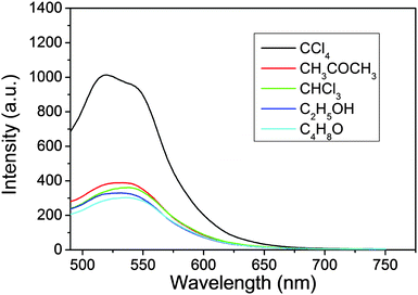
In producing the solid powder composites, the suspensions of C-NPs/silica gel composites are maintained at 45 °C for evaporation of the solvents. Because the emission intensity of C-NPs strongly depends on the dispersibility in silica gel, the distribution of C-NPs in silica gel is the key to preserve the luminescence. To optimize the luminescence of the composites, the influence of different solvents and their combinations are studied (Fig. 6 and Tables S1–S3, ESI†). As shown in Fig. 6, the acetic ether suspension of the C-NPs/silica gel composites is respectively mixed with five polar solvents, including ethyl acetate, CCl4, CHCl3, acetone and alcohol, and solvent evaporation is performed to produce the solid powder composites. The concentration of the composites and the evaporation temperature are fixed. It is found that although the C-NPs show the highest luminescence in ethyl acetate (Table S1, ESI†), the powder made from ethyl acetate–CCl4 binary solvent evaporation exhibits a higher emission intensity than any other solvent combination (Fig. 6 and Table S2, ESI†). This implies that the ethyl acetate–CCl4 binary solvents facilitate the homogeneous distribution of C-NPs in the silica gel during the solvent evaporation. We have tried to distinguish the composites with aggregates of C-NPs by TEM. However, due to the similar contrast of silica gel and C-NPs, they cannot be distinguished (Fig. S1, ESI†). Table 2 compares the dielectric constants and boiling points of the aforementioned five solvents. At the same temperature, higher boiling point solvents possess a lower evaporation rate, which results in the slow drying of the composites. The slower solvent evaporation permits the formation of stronger hydrogen bonding interactions between the C-NPs and silica gel, thus avoiding the aggregation of C-NPs. Consequently, strong luminescence is preserved. In comparison, the rapid evaporation of the lower boiling point solvents weakens the hydrogen bonding interactions, which leads to serious aggregation of C-NPs and a decrease in the emission intensity. So, high boiling point solvents facilitate the preservation of strong luminescence. On the other hand, hydrogen bonding attraction becomes stronger in solvents with a lower dielectric constant. This means that in CCl4, the interaction between C-NPs and silica gel is stronger than the other solvents. As a result, the C-NPs distribute well on the silica gel, thus preserving the strong luminescence. Note that strong hydrogen bonding also exists in C-NPs, which are able to form aggregates of C-NPs at high concentrations of C-NPs. As a result, the strongest luminescence appears at proper C-NPs concentrations and solvent ratios (Fig. S2 and Table S3, ESI†).
| Solvents | Dielectric constant | Boiling point (°C) |
|---|---|---|
| Ethyl acetate | 6.0 | 77.1 |
| CHCl3 | 4.8 | 61.3 |
| CCl4 | 2.2 | 76.8 |
| Alcohol | 24.3 | 78.1 |
| Acetone | 17.7 | 56.2 |
According to the aforementioned results, the formation process of the C-NPs/silica gel composites is illustrated in Scheme 1. As C-NPs and silica gel are dispersed in dual solvents, the C-NPs tend to adsorb on the silica gel through hydrogen bonding attractions between silica gel –OH and C-NPs –COOH. With solvent evaporation, the concentration of C-NPs and silica gel gradually increases, which facilitates the adsorption of C-NPs on the silica gel. On the other hand, C-NPs and silica gel also have a tendency of phase separation to form a thermodynamically stable system at high concentrations. If the hydrogen bonding attraction between the C-NPs and silica gel is strong enough, the phase separation will be partially suppressed. Slow solvent evaporation permits the C-NPs and silica gel interaction to be strengthened, thus producing more homogeneous composites.
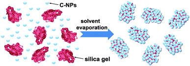 | ||
| Scheme 1 Schematic illustration of the formation of C-NPs/silica gel composites through a dual solvent evaporation route. | ||
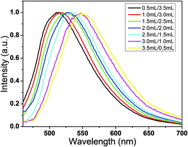
The optimum ratio of C-NPs and silica gel is studied by fixing the amount of silica gel while altering the C-NPs (Fig. 7). With the increase of C-NPs, the emission peak red shifts, while the emission intensity has no obvious change. Note that in this process, the amount of C-NPs increases from 0.5 to 3.5 mL. This means that the excess of C-NPs do not contribute to the emission intensity. With the increase of C-NPs, the average concentration of C-NPs on silica gel increases, thus lowering the effect of silica gel in separating the C-NPs. So, the excess C-NPs aggregate, which leads to the emission redshift and emission quenching via re-absorption and energy transfer. This phenomenon can be used to tune the emission intensity and in particular the emission color of the composites. For example, a WLED requires the combination of the InGaN blue emission and the C-NPs yellow-green emission. In fabricating WLEDs, the composites made from the mixtures of 2.0 mL C-NPs ethyl acetate solution, 2.0 mL CCl4, and 0.8 g silica gel are selected.
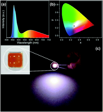
A WLED prototype was fabricated by mixing the composites powder and PDMS precursor, placing them on a commercial InGaN UV-blue emitting chip, and solidifying at 80 °C for 3 h. Fig. 8a indicates the emission spectrum of the LED. The spectrum presents a sharp emission at 460 nm and a broad emission at 590 nm, which is the combination of InGaN blue emission and C-NPs yellow-green emission. In this context, the role of the C-NPs is as the color conversion material, which absorbs the blue emission of the InGaN chip and emits a yellow-green emission. Fig. 8b shows the Commission Internationale de l'Eclairage (CIE) chromaticity coordinate (x, y) of (0.28, 0.29), consist with the coordinate of cold white light. Fig. 8c exhibits a photograph of the WLED under a working voltage of 3.0 V. A strong white emission is observed.
4. Conclusion
In summary, luminescent C-NPs are combined with a commercial silica gel via a dual solvent evaporation route for preserving the emission. Systematic investigation reveals that the use of solvent mixtures with a low dielectric constant and a relative high boiling point preserves the strong luminescence of the C-NPs. Under such conditions, the slow evaporation of solvents permits strong hydrogen bonding attractions to form between the C-NPs and silica gel, thus overcoming the aggregation of C-NPs, which is the main reason for the C-NPs emission decrease. The C-NPs/silica gel composites are combined with PDMS and coated on a commercial InGaN UV-blue emitting chip. As the color conversion layer, the composites absorb the blue emission of the InGaN chip and emit the yellow-green emission of C-dots. Thus a white light emission is achieved.Author contributions
H. C. Sun, H. Zhang and J. L. Jiang proposed and supervised the project. Y. Cui, X. Y. Bu, Y. Liu and H. Zhang designed and performed the experiments and co-wrote the paper. H. Y. Zou, X. W. Xu, D. Zhou, H. W. Liu and X. Zhang participated in most experiments. All authors discussed the results and commented on the manuscript.Acknowledgements
This work was supported by the National key research and development program of China (2016YFB0401701), NSFC (81320108011, 81271111), Natural Science Foundation of Jilin Province (20140101048JC, 20150101135JC), and China's General Administration of Quality Supervision, Inspection and Quarantine Bureau of Science and Technology Planning Project (2014IK135).References
- S. N. Baker and G. A. Baker, Angew. Chem., Int. Ed., 2010, 49, 6726–6744 CrossRef CAS PubMed.
- S. Zhu, Y. Song, X. Zhao, J. Shao, J. Zhang and B. Yang, Nano Res., 2015, 8, 355–381 CrossRef CAS.
- Y. P. Sun, B. Zhou, Y. Lin, W. Wang, K. A. S. Fernando, P. Pathak, M. J. Meziani, B. A. Harruff, X. Wang, H. Wang, P. G. Luo, H. Yang, M. E. Kose, B. Chen, L. M. Veca and S. Y. Xie, J. Am. Chem. Soc., 2006, 128, 7756–7757 CrossRef CAS PubMed.
- X. Zhou, S. Guo and J. Zhang, ChemPhysChem, 2013, 14, 2627–2640 CrossRef CAS PubMed.
- S. Zhu, Q. Meng, L. Wang, J. Zhang, Y. Song, H. Jin, K. Zhang, H. Sun, H. Wang and B. Yang, Angew. Chem., Int. Ed., 2013, 52, 3953–3957 CrossRef CAS PubMed.
- V. Gupta, N. Chaudhary, R. Srivastava, G. D. Sharma, R. Bhardwaj and S. Chand, J. Am. Chem. Soc., 2011, 133, 9960–9963 CrossRef CAS PubMed.
- H. Choi, S. J. Ko, Y. Choi, P. Joo, T. Kim, B. R. Lee, J. W. Jung, H. J. Choi, M. Cha, J. R. Jeong, I. W. Hwang, M. H. Song, B. S. Kim and J. Y. Kim, Nat. Photonics, 2013, 7, 732–738 CrossRef CAS.
- T. Lai, E. Zheng, L. Chen, X. Wang, L. Kong, C. You, Y. Ruan and X. Weng, Nanoscale, 2013, 5, 8015–8021 RSC.
- S. Qu, X. Wang, Q. Lu, X. Liu and L. Wang, Angew. Chem., Int. Ed., 2012, 51, 12215–12218 CrossRef CAS PubMed.
- H. Tao, K. Yang, Z. Ma, J. Wan, Y. Zhang, Z. Kang and Z. Liu, Small, 2012, 8, 281–290 CrossRef CAS PubMed.
- S. Zhu, J. Zhang, C. Qiao, S. Tang, Y. Li, W. Yuan, B. Li, L. Tian, F. Liu, R. Hu, H. Gao, H. Wei, H. Zhang, H. Sun and B. Yang, Chem. Commun., 2011, 47, 6858–6860 RSC.
- R. Garcia, N. S. Losilla, J. Martínez, R. V. Martinez, F. J. Palomares, Y. Huttel, M. Calvaresi and F. Zerbetto, Appl. Phys. Lett., 2010, 96, 143110 CrossRef.
- R. Ye, C. Xiang, J. Lin, Z. Peng, K. Huang, Z. Yan, N. P. Cook, E. L.G. Samuel, C. C. Hwang, G. Ruan, G. Ceriotti, A. R. O. Raji, A. A. Martí and J. M. Tour, Nat. Commun., 2013, 4, 2943 Search PubMed.
- Y. Yang, D. Wu, S. Han, P. Hu and R. Liu, Chem. Commun., 2013, 49, 4920–4922 RSC.
- L. Tang, R. Ji, X. Cao, J. Lin, H. Jiang, X. Li, K. S. Teng, C. M. Luk, S. Zeng, J. Hao and S. P. Lau, ACS Nano, 2012, 6, 5102–5110 CrossRef CAS PubMed.
- F. Wang, S. Pang, L. Wang, Q. Li, M. Kreiter and C. Y. Liu, Chem. Mater., 2010, 22, 4528–4530 CrossRef CAS.
- X. Zhang, Y. Zhang, Y. Wang, S. Kalytchuk, S. V. Kershaw, Y. Wang, P. Wang, T. Zhang, Y. Zhao, H. Zhang, T. Cui, Y. Wang, J. Zhao, W. W. Yu and A. L. Rogach, ACS Nano, 2013, 7, 11234–11241 CrossRef CAS PubMed.
- F. Wang, Y. H. Chen, C. Y. Liu and D. G. Ma, Chem. Commun., 2011, 47, 3502–3504 RSC.
- S. Lee, J. Y. Hong and J. Jang, ACS Nano, 2013, 7, 5784–5790 CrossRef CAS PubMed.
- F. Wang, M. Kreiter, B. He, S. Pang and C. Y. Liu, Chem. Commun., 2010, 46, 3309–3311 RSC.
- X. Guo, C. F. Wang, Z. Y. Yu, L. Chen and S. Chen, Chem. Commun., 2012, 48, 2692–2694 RSC.
- W. Kwon, S. Do, J. Lee, S. Hwang, J. K. Kim and S. W. Rhee, Chem. Mater., 2013, 25, 1893–1899 CrossRef CAS.
- C. X. Li, C. Yu, C. F. Wang and S. Chen, J. Mater. Sci., 2013, 48, 6307–6311 CrossRef CAS.
- Q. L. Chen, C. F. Wang and S. Chen, J. Mater. Sci., 2013, 48, 2352–2357 CrossRef CAS.
- X. T. Feng, F. Zhang, Y. L. Yang, Y. Zhang, Y. Z. Yang and X. L. Liu, Appl. Phys. Lett., 2015, 107, 213102 CrossRef.
- S. K. Bhunia, S. Nandi, R. Shikler and R. Jelinek, Nanoscale, 2016, 8, 3400–3406 RSC.
- B. De, B. Voit and N. Karak, ACS Appl. Mater. Interfaces, 2013, 5, 10027–10034 CAS.
- Y. Zhou, Z. B. Qu, Y. Zeng, T. Zhou and G. Shi, Biosens. Bioelectron., 2014, 52, 317–323 CrossRef CAS PubMed.
- R. Liu, D. Wu, S. Liu, K. Koynov, W. Knoll and Q. Li, Angew. Chem., Int. Ed., 2009, 48, 4598–4601 CrossRef CAS PubMed.
- Z. A. Qiao, Q. Huo, M. Chi, G. M. Veith, A. J. Binder and S. Dai, Adv. Mater., 2012, 24, 6017–6021 CrossRef CAS PubMed.
- Y. Mao, Y. Bao, D. Han, F. Li and L. Niu, Biosens. Bioelectron., 2012, 38, 55–60 CrossRef CAS PubMed.
- M. M. van Schooneveld, A. Gloter, O. Stephan, L. F. Zagonel, R. Koole, A. Meijerink, W. J. M. Mulder and F. M. F. de Groot, Nat. Nanotechnol., 2010, 5, 538–544 CrossRef CAS PubMed.
- C. B. Murray, C. R. Kagan and M. G. Bawendi, Science, 1995, 270, 1335–1338 CAS.
- Y. Fang, S. Guo, D. Li, C. Zhu, W. Ren, S. Dong and E. Wang, ACS Nano, 2012, 6, 400–409 CrossRef CAS PubMed.
- T. Otto, M. Müller, P. Mundra, V. Lesnyak, H. V. Demir, N. Gaponic and A. Eychmüller, Nano Lett., 2012, 12, 5348–5354 CrossRef CAS PubMed.
- Z. Wu, J. Liu, Y. Gao, H. Liu, T. Li, H. Zou, Z. Wang, K. Zhang, Y. Wang, H. Zhang and B. Yang, J. Am. Chem. Soc., 2015, 137, 12906–12913 CrossRef CAS PubMed.
- D. Zhou, M. Liu, M. Lin, X. Bu, X. Luo, H. Zhang and B Yang, ACS Nano, 2014, 8, 10569–10581 CrossRef CAS PubMed.
- D. Yao, H. Liu, Y. Liu, C. Dong, K. Zhang, Y. Sheng, J. Cui, H. Zhang and B. Yang, Nanoscale, 2015, 7, 18570–18578 RSC.
- Y. Sun, W. Cao, S. Li, S. Jin, K. Hu, L. Hu, Y. Huang, X. Gao, Y. Wu and X. J. Liang, Sci. Rep., 2013, 3, 3036 Search PubMed.
- X. Zhang, S Wang, L. Xu, L. Feng, Y. Ji, L. Tao, S. Li and Y. Wei, Nanoscale, 2012, 4, 5581–5584 RSC.
- D. Zhou, H. Zou, M. Liu, K. Zhang, Y. Sheng, J. Cui, H. Zhang and B. Yang, ACS Appl. Mater. Interfaces, 2015, 7, 15830–15839 CAS.
Footnote |
| † Electronic supplementary information (ESI) available. See DOI: 10.1039/c6qm00053c |
| This journal is © the Partner Organisations 2017 |

