Ultrathin CNTs@FeOOH nanoflake core/shell networks as efficient electrocatalysts for the oxygen evolution reaction†
Yongqi
Zhang‡
a,
Guichong
Jia‡
a,
Huanwen
Wang
a,
Bo
Ouyang
b,
Rajdeep Singh
Rawat
b and
Hong Jin
Fan
*a
aSchool of Physical and Mathematical Sciences, Nanyang Technological University, Singapore 637371, Singapore. E-mail: fanhj@ntu.edu.sg
bNatural Sciences and Science Education, National Institute of Education, Nanyang Technological University, 637616, Singapore
First published on 24th October 2016
Abstract
Transition metal (oxy)hydroxides are a class of promising non-noble metal based electrocatalysts utilized for the water oxidation reaction but suffer from poor electrical conductivity. Herein, we report on CNTs@ultrathin FeOOH nanoflake core/shell networks on a carbon cloth (CNTs@FeOOH/CC) for the oxygen evolution reaction (OER). With the assistance of a layer of ZnO formed via atomic layer deposition (ALD), ultrathin FeOOH nanoflakes are uniformly grown on CNTs. The CNT cores serve as highly conductive channels to facilitate the transfer of electrons, which effectively enhances the electrical conductivity of FeOOH. Furthermore, the interwoven network structure increases the mass loading and utilization of FeOOH. As a result, the CNTs@FeOOH/CC catalyst exhibits a high OER performance, with features such as a low onset overpotential, large anodic current density, small Tafel slope and excellent long-term electrolysis durability, which are highly desirable for a promising OER electrocatalyst.
Introduction
Catalytic water splitting to generate oxygen and hydrogen gases provides a promising method to store intermittent renewable energies, such as wind and solar energies, and thus promises to reduce the energy and environmental problems caused by burning fossil fuels.1 However, the sluggish oxygen evolution reaction (OER) limits the efficiency of water electrolysis and photoelectrolysis due to its four-electron transfer process.2–5 Highly efficient catalysts are urgently needed to accelerate the OER reaction.6–8 Generally, an ideal catalyst possesses the following characteristics: the optimal adsorption energy between catalysts and the intermediates, fast electron transfer properties and a high electrochemical active surface area (EASA) (i.e. large number of active sites). Among the studied OER catalysts, noble metal-based materials (e.g., IrO2 and RuO2) show the best catalytic performance. Unfortunately, their scarce nature and high cost considerably hinder their industrial application.9–11 Over the past few years, first row transition metal (Mn, Fe, Co, Ni, etc.) based oxides and (oxy)hydroxides have attracted enormous attention as next generation OER catalysts due to their abundance, low cost, environmental friendliness and impressive catalytic performance.12–16In the past, pure iron (Fe)-based oxides and (oxy)hydroxides were considered to be less active experimentally.12 However, recent research indicates that thin FeOxHy films show the highest turnover frequencies (TOF) among the first row transitional metal (oxy)hydroxides and are much more active than previously thought.17 The apparent poor activity is primarily due to its very poor electrical conductivity. In other words, the poor electrical conductivity of FeOxHy limits the active site on the surface to be fully activated during OER. Thus, enhancing the conductivity of FeOxHy is the key step to improving its catalytic performance.18,19 A combination of active materials with conductive additives is a general method to improve the electrical conductivity of electrode materials.20,21 However, in most cases, the high EASA of active materials, another key factor that highly affects the catalytic activity, is usually sacrificed. It is, therefore, essential to construct an electrode with both high electrical conductivity and EASA.19 FeOOH films on conductive metal/metal oxide nanoarrays (Co, CeO2) via electrodeposition have been developed by Li's group,14,18 which exhibit excellent OER activity. The core arrays not only enhance the whole conductivity of the electrodes, but also offer a relatively high EASA. Even so, further efforts are still needed to achieve higher efficiency FeOOH catalysts.
In this manuscript, we construct CNTs@ultrathin FeOOH nanoflake core/shell networks on carbon cloth (CNTs@FeOOH/CC) through the combination of chemical vapor deposition (CVD), ALD and the subsequent sacrificial template-accelerated hydrolysis (STAH). Such a unique catalyst shows several structural merits: firstly, the interwoven CNTs grown via CVD act as electron superhighways due to their high electrical conductivity, which greatly overcomes the poor conductivity of FeOOH. Direct contact of the active material (iron oxyhydroxides) and the CNTs eliminates the use of a binder, which endows the electrode with minimum resistivity and strong adhesion. Secondly, the network structure of the CNTs with a diameter of ∼20 nm can offer a high specific surface area for growing more active materials. And the CNT networks are extremely light and flexible compared to metal or metal oxide substrates. Finally, a thin uniform ALD ZnO sacrificial layer can guarantee uniform growth of FeOOH on the CNTs, which is the key to high electrocatalytic OER activity. Therefore, the interwoven network structure not only improves the electrical conductivity, but also maintains the high surface area of the catalyst. The electrochemical measurements show that CNTs@FeOOH/CC exhibits a high OER catalytic performance, with features such as low onset potential, high OER activity, excellent durability and structural stability.
Experimental section
Preparation of CNTs on a carbon cloth (CNTs/CC)
CNTs/CC was prepared using a general CVD method. First, a carbon cloth was cleaned in ethanol and DI water via ultrasonic treatment for 10 min in order. Then the cleaned carbon cloth was dipped into ethanol solution consisting of 0.2 M Ni(NO3)2 and 7 wt% ethylene glycol for 12 h. After drying in an oven at 80 °C for 1 h, the dipped carbon cloth was put into a quartz tube furnace under a mixed gas flow of 2% (H2) and 98% (Ar) for 15 min and then the temperature was elevated to 600 °C. The nickel salt was reduced into nickel nanoparticles after keeping the sample under 600 °C for 15 min. After that, the carbon source (ethanol) was bubbled into the quartz tube using mixed gas at 600 °C under ambient pressure to participate in the reaction. After reacting for 1 h, CNTs/CC was obtained and the sample was taken out and cooled down to room temperature rapidly.Preparation of CNTs@FeOOH/CC
CNTs@FeOOH/CC was synthesized using a combination of atomic layer deposition ALD and STAH. First, ZnO was deposited evenly on the CNTs@carbon cloth using ALD (Beneq TFS 200) at 120 °C using diethyl zinc (DEZ, 99.99%, Sigma-Aldrich) and H2O as the Zn and O precursors, respectively. The thickness was controlled by the cycles, in this work, 50 cycles were used to obtain around a 10 nm thick layer of ZnO. The CNTs@ZnO/carbon clothes were then immersed into a 50 mL aqueous solution containing 0.3 g of FeCl3·6H2O and kept at room temperature for 12 h to convert ZnO into FeOOH and remove the Ni particles completely. The main chemical reactions involved in this process can be illustrated as follows:| Fe3+ + 2H2O ↔ FeOOH + 3H+ | (1) |
| ZnO + 2H+ → Zn2+ + H2O | (2) |
| 2Fe3+ + Ni → 2Fe2+ + Ni2+. | (3) |
Preparation of FeOOH nanoflakes on a carbon cloth (FeOOH/CC)
As mentioned above, the ZnO film was directly deposited on a cleaned carbon cloth via ALD firstly. Then ZnO/CC samples were immersed into a 50 mL aqueous solution containing 0.3 g of FeCl3·6H2O and kept at room temperature for 12 h to convert ZnO into FeOOH.Preparation of FeOOH powder
The powder used was prepared in the following way: 1 M KOH was added dropwise to a 0.1 M FeCl3 solution under stirring until the pH was equal to 7. The suspension was stirred for another 1 hour. Then the precipitates of FeOOH were collected via centrifugation and washed with large amounts of DI water.Materials characterization
The samples were characterized using X-ray diffraction (XRD, 6000 Shimadzu), field-emission scanning electron microscopy (FESEM, FEI SIRION), high-resolution transmission electron microscopy (HRTEM, JEOL-2010 UHR), X-ray photoelectron spectroscopy (XPS, PHI 5700) and Raman spectroscopy (WITec-CRM200 Raman system with a laser wavelength of 532 nm).Electrochemical characterization
All electrochemical measurements were studied on an electrochemical workstation (Zahner zennuim, Germany) with a three-electrode system. The CNTs@FeOOH/CC films were directly used as the working electrodes. The FeOOH powder electrodes were prepared by loading catalyst ink onto the glass carbon (1 mg cm−2). The ink was a mixture of 10 mg of FeOOH, 0.48 mL of DI water, 0.48 mL of isopropanol and 40 μL of 0.5% Nafion. A Pt foil and Ag/AgCl (in 3 M KCl) were utilized as the counter electrode and the reference electrode, respectively. The electrolyte was 1 M KOH. All potentials were calculated with respect to the reversible hydrogen electrode (RHE) via the following equation: E(RHE) = E(Ag/AgCl) + 0.0591 pH + 0.210 V. All potentials were referred to the RHE without specification. The linear sweep voltammetry (LSV) was measured at a scan rate of 5 mV s−1. Before the LSV tests, the electrodes were first conducted for 10 cycles of cyclic voltammetry (CV) in the range of 0 to 0.6 V vs. Ag/AgCl to stabilize the current at 50 mV s−1. The Tafel plots were derived from the LSV curves at 1 mV s−1. Electrochemical impedance spectroscopy (EIS) was conducted at 1.23 V, with a frequency ranging from 100 kHz to 0.01 Hz and an AC amplitude of 5 mV. The stability performance was measured at different specified current densities (10, 30, 50 and 100 mA cm−2) for 10 h. The current density was calculated according to the geometric area of the electrode. The Faradaic efficiency was estimated using the volumetric method. The evolved oxygen gas on the CNTs@FeOOH/CC working electrode was collected in a 25 mL measuring cylinder, which was filled with electrolyte. Electrolysis was carried out at a current density of 10 mA cm−2 for 3.5 h under standard conditions (25 °C, 1 atm). The time for each 1 mL of collected O2 gas was recorded. The accumulated charge passing through the working electrode was calculated using the equation (Q = It).Results and discussion
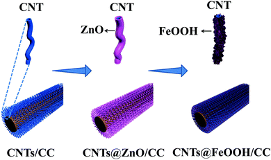
The fabrication process of CNTs@FeOOH/CC is presented in Fig. 1, which mainly involves three steps. The pure carbon cloth in Fig. S1 (ESI†) shows that each carbon fiber has a smooth surface and the average diameter is around 10 μm. In the first step, CNT networks are grown on a carbon cloth via a modified CVD method as reported previously.22 A layer of high density intertwined CNTs is uniformly formed on the carbon cloth fibers after CVD. The carbon cloth fibers coated with CNTs had an average diameter of ∼14 μm (Fig. 2a). Further insight shows that these interwoven CNTs with diameters of 10–40 nm, which is in agreement with the TEM results, (Fig. 2d) form a porous conductive network. In the second step, a thin layer of ZnO is directly deposited onto CNTs/CC using ALD. The network structure is perfectly retained after ZnO deposition as shown in Fig. 2b, indicating that ZnO is uniformly coated on every CNT. The thickness of ZnO can be accurately controlled via the cycles of ALD.23 Here, the thickness of ZnO coated on the CNTs is around 10 nm as seen in the TEM image shown in Fig. 2e. In the last step, the ZnO-coated CNT film is immersed into FeCl3 solution for 24 h. Fe3+ ions hydrolyze into FeOOH colloid and H+. This reaction occurs preferentially around the layer of ZnO due to the H+ consumed by ZnO, which promotes the hydrolysis reaction in the vicinity of ZnO. As a result, the precipitated FeOOH is deposited on the CNTs, accordingly the CNTs@FeOOH/CC is fabricated. SEM images of CNTs@FeOOH with different magnifications are shown in Fig. 2c, which clearly show that the interwoven network is maintained well and a layer of nanoflakes covers the surface of the CNTs uniformly. The TEM image shown in Fig. 2f confirms that the shell (∼15 nm) of CNTs@FeOOH is composed of FeOOH nanoflakes. For comparison, FeOOH powders were also prepared as shown in Fig. S2 (ESI†), which agglomerate seriously.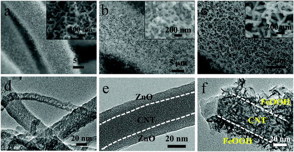 | ||
| Fig. 2 Electron micrographs (SEM and TEM) of the CNTs/CC (a and d), CNTs@ZnO/CC (b and e) and CNTs@FeOOH/CC (c and f) samples. Insets are the corresponding enlarged views. | ||
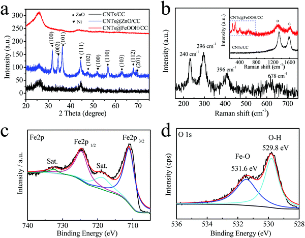
To reveal the structure and composition of the sample, XRD, Raman spectroscopy and XPS analyses were carried out (Fig. 3). The as-prepared interwoven CNTs film shows two broad peaks at around 25° and 44°, which correspond to the (002) and (101) diffraction peaks of carbon (CNTs/CC) (Fig. S3, ESI†). Two peaks at 44.5° and 51.8° are indexed to the (111) and (100) reflections of Ni (JCPDS No. 04-0850), which acts as a catalyst for the formation of the CNTs during CVD.24 More diffraction peaks appear after ZnO deposition, which can be indexed to the hexagonal structure of ZnO (JCPDS No. 36-1451).23,25 The crystalline property of ZnO is due to the high deposition temperature. After immersion in FeCl3 solution for 24 h, the layer of ZnO is replaced by amorphous FeOOH and the Ni metal is oxidized by Fe3+ into Ni2+, so only the peaks of CNTs/CC are left as seen in Fig. 3a.23,26 In the full XPS spectrum of CNTs@FeOOH/CC (Fig. S4, ESI†), no peaks indexed to Ni element are presented, confirming that Ni is dissolved completely. The typical characteristic peaks of FeOOH (240, 296, 396, and 678 cm−1) are noticed in the low wavenumber region of the Raman spectra of CNTs@FeOOH/CC (Fig. 3b).27,28 Two peaks at 1350 and 1585 cm−1 are typical peaks of CNTs and correspond to the D and G bands, respectively.22 The XPS spectrum of CNTs@FeOOH/CC in Fig. 3c shows typical characteristics of FeOOH with two main peaks located at 710.9 and 724.6 eV.14,29 The XPS spectrum of O(1s) exhibits two strong peaks at 531.6 and 529.8 eV (Fig. 3d). The higher binding energy peak is due to the OH ion and the lower binding energy peak is derived from M–O, which are consistent with a previous report.14
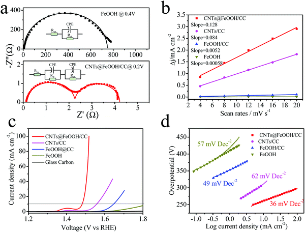
The fast electron transfer, as mentioned, is one of the key requisites of an efficient electrocatalyst. Electrochemical impedance spectroscopy (EIS) was carried out in 1 M KOH to study the electron transfer kinetics occurring at the interface of the electrode/electrolyte (Fig. 4a). At the onset potential (1 mA cm−2), the observed Rct value (1.9 Ω) of CNTs@FeOOH/CC is largely smaller than that of the FeOOH powder (742 Ω), suggesting a much faster electron transfer during the electrochemical reaction. It indicates that the CNT network is able to enormously improve the conductivity of the entire electrode. In addition, the high density of active sites at a specific geometric area is another prerequisite for a good electrocatalyst. Here, the EASA is evaluated via the electrochemical double-layer capacitance measurement (Cdl; Fig. 4b and Fig. S5, ESI†).30 The capacitance of CNTs/CC is around 42 mF cm−2 and that of CNTs@FeOOH/CC increased slightly to 64 mF cm−2. In contrast, the capacitance of the FeOOH powder is only 0.29 mF cm−2. The electrochemical capacitance serves as an approximate guide for surface area within an order-of-magnitude accuracy. The high Cdl value of CNTs@FeOOH/CC can be attributed to the CNT template, which increases the specific surface areas and increases mass loading and results in uniform dispersion of the FeOOH nanoparticles without evident agglomeration. Therefore, the enhanced electrocatalytic performance of the CNTs@FeOOH/CC electrode can be explained by increased surface active sites and a high-conductivity path rendered by the CNTs.
The OER activity of the CNTs@FeOOH/CC electrode was measured via a standard three-electrode system in 1 M KOH. The FeOOH powder, CNTs/CC and glass carbon electrode were also measured for comparison. The CNTs/CC samples were immersed in FeCl3 solution to remove the Ni catalyst before the electrochemical tests. The linear-sweep voltammograms (LSVs) at 5 mV s−1 after iR correction for all electrodes are presented in Fig. 4c. It can be seen that the CNTs@FeOOH/CC sample shows the highest catalytic activity across the whole potential window (lowest onset potential and highest current density). Specifically, it only requires 250 mV of overpotential to reach the current density of 10 mA cm−2, which is significantly lower than that of FeOOH powder (over 550 mV). The OER activity of the glass carbon is negligible. The nontrivial catalytic activity of CNTs/CC can be attributed to defects on the surface of the CNTs.31 As for the Tafel plots (see Fig. 4d), the CNTs@FeOOH/CC shows a Tafel slope of ∼36 mV dec−1, which is much smaller than those of the FeOOH powder (46 mV dec−1) and CNTs/CC (62 mV dec−1). The above results clearly show that the CNT network can significantly improve the OER catalytic activity of FeOOH. Compared with other nonprecious metal-based catalysts (such as NiFe LDH,7 mesoporous Ni3N nanosheets,32 CoFe2O4/PANI-MWCNTs,33 NiCo2O4 nanowire arrays,30 and Ni(OH)2/CNTs31), our CNTs@FeOOH/CC shows a comparably high catalytic performance under similar conditions (see Table S1, ESI†).
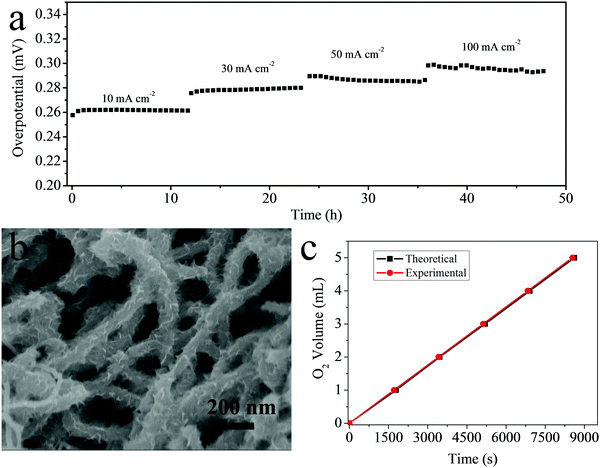
Aside from the high OER activity, stability is another important parameter to evaluate an electrocatalyst. The stability test was conducted sequentially for over 48 h at different current densities (10, 30, 50 and 100 mA cm−2). As shown in Fig. 5a, the time dependence of the current density for CNTs@FeOOH/CC at different overpotentials shows only a little degradation after a long period, suggesting the excellent stability of CNTs@FeOOH/CC for electrochemical water oxidation. This stable cycling performance can be partially attributed to the strong adhesion between FeOOH nanoflakes and CNTs as well as the mechanical robustness of the network structure. As revealed in the SEM image after a 48 h stability test (Fig. 5b), the morphology of the original network structure is well preserved and the FeOOH nanoflakes on the CNTs remained almost unchanged, indicating the robust stability of the film. The robust network structure provides a strong mechanical support for the long-life duration.
To confirm that the current was completely associated with water oxidation, a Faradaic efficiency measurement was carried out at a constant applied current density (30 mA cm−2) and is shown in Fig. 5c. The Faradic efficiency was calculated by comparing the amount of gas collected experimentally with the theoretically calculated value. The near 100% Faradic efficiency (coincidence of both values) indicates that almost no side reaction occurred during the water oxidation reaction.7 The improved and stable catalytic performance of the as-prepared CNTs@FeOOH/CC network can be mainly attributed to the unique architecture including the interwoven CNT network, better electron transport provided by the CNTs, porous and ultrathin FeOOH nanoflake shells, the density of active sites of the catalyst and strong mechanical adhesion.
Conclusion
We have designed and fabricated CNTs@FeOOH/CC as an efficient electrocatalyst for OER in alkaline media. Through the STAH method using ALD ZnO as a sacrificial template, a layer of ultrathin porous FeOOH nanoflakes was covered uniformly on a highly interwoven CNT network. The unique network structure of CNTs@FeOOH/CC made it possible to utilize FeOOH efficiently for electrocatalytic reaction with more active sites exposed to the electrolyte and fast charge transport facilitated by the CNT core network, which played a key role in improving the electrochemical performance of FeOOH. As a result, the obtained CNTs@FeOOH/CC exhibited an improved catalytic performance with a small overpotential of around 250 mV to reach a current density of 10 mA cm−2 and with an outstanding stability at different current densities. Our study provides a feasible way to achieve efficient OER electrocatalysts using inexpensive and earth abundant elements, especially for these poor electrical conductivity metal (oxy)hydroxides.Acknowledgements
This work was supported by the Singapore MOE AcRF Tier 1 grant (RG98/15) and NIE RS-SAA grant RS 6/14 RSR.References
- Y. Jiao, Y. Zheng, M. Jaroniec and S. Z. Qiao, Chem. Soc. Rev., 2015, 44, 2060–2086 RSC.
- K. Zhang, M. Ma, P. Li, D. H. Wang and J. H. Park, Adv. Energy Mater., 2016, 1600602 CrossRef.
- I. C. Man, H.-Y. Su, F. Calle-Vallejo, H. A. Hansen, J. I. Martínez, N. G. Inoglu, J. Kitchin, T. F. Jaramillo, J. K. Nørskov and J. Rossmeisl, ChemCatChem, 2011, 3, 1159–1165 CrossRef CAS.
- E. Fabbri, A. Habereder, K. Waltar, R. Kotz and T. J. Schmidt, Catal. Sci. Technol., 2014, 4, 3800–3821 CAS.
- F. Dionigi and P. Strasser, Adv. Energy Mater., 2016, 1600621 CrossRef.
- Y. Zhang, B. Ouyang, J. Xu, G. Jia, S. Chen, R. S. Rawat and H. J. Fan, Angew. Chem., Int. Ed., 2016, 55, 8670–8674 CrossRef CAS PubMed.
- R. Chen, G. Sun, C. Yang, L. Zhang, J. Miao, H. Tao, H. Yang, J. Chen, P. Chen and B. Liu, Nanoscale Horiz., 2016, 1, 156–160 RSC.
- Y. Zhao, R. Nakamura, K. Kamiya, S. Nakanishi and K. Hashimoto, Nat. Commun., 2013, 4, 2390 Search PubMed.
- C. C. L. McCrory, S. Jung, J. C. Peters and T. F. Jaramillo, J. Am. Chem. Soc., 2013, 135, 16977–16987 CrossRef CAS PubMed.
- Y. Lee, J. Suntivich, K. J. May, E. E. Perry and Y. Shao-Horn, J. Phys. Chem. Lett., 2012, 3, 399–404 CrossRef CAS PubMed.
- T. Reier, M. Oezaslan and P. Strasser, ACS Catal., 2012, 2, 1765–1772 CrossRef CAS.
- R. Subbaraman, D. Tripkovic, K. C. Chang, D. Strmcnik, A. P. Paulikas, P. Hirunsit, M. Chan, J. Greeley, V. Stamenkovic and N. M. Markovic, Nat. Mater., 2012, 11, 550–557 CrossRef CAS PubMed.
- K. L. Nardi, N. Y. Yang, C. F. Dickens, A. L. Strickler and S. F. Bent, Adv. Energy Mater., 2015, 5, 1500412 CrossRef.
- J. X. Feng, H. Xu, Y. T. Dong, S. H. Ye, Y. X. Tong and G. R. Li, Angew. Chem., Int. Ed., 2016, 55, 3694–3698 CrossRef CAS PubMed.
- A. Ramírez, P. Hillebrand, D. Stellmach, M. M. May, P. Bogdanoff and S. Fiechter, J. Phys. Chem. C, 2014, 118, 14073–14081 Search PubMed.
- M. S. Burke, S. Zou, L. J. Enman, J. E. Kellon, C. A. Gabor, E. Pledger and S. W. Boettcher, J. Phys. Chem. Lett., 2015, 6, 3737–3742 CrossRef CAS PubMed.
- M. S. Burke, L. J. Enman, A. S. Batchellor, S. Zou and S. W. Boettcher, Chem. Mater., 2015, 27, 7549–7558 CrossRef CAS.
- J. X. Feng, S. H. Ye, H. Xu, Y. X. Tong and G. R. Li, Adv. Mater., 2016, 28, 4698–4703 CrossRef CAS PubMed.
- F. Yan, C. Zhu, S. Wang, Y. Zhao, X. Zhang, C. Li and Y. Chen, J. Mater. Chem. A, 2016, 4, 6048–6055 CAS.
- Y. Yu, W. Gao, Z. Shen, Q. Zheng, H. Wu, X. Wang, W. Song and K. Ding, J. Mater. Chem. A, 2015, 3, 16633–16641 CAS.
- X. Xia, Y. Zhang, D. Chao, C. Guan, Y. Zhang, L. Li, X. Ge, I. M. Bacho, J. Tu and H. J. Fan, Nanoscale, 2014, 6, 5008–5048 RSC.
- X. Xia, D. Chao, Y. Zhang, J. Zhan, Y. Zhong, X. Wang, Y. Wang, Z. X. Shen, J. Tu and H. J. Fan, Small, 2016, 12, 3048–3058 CrossRef CAS PubMed.
- J. Luo, J. Liu, Z. Zeng, C. F. Ng, L. Ma, H. Zhang, J. Lin, Z. Shen and H. J. Fan, Nano Lett., 2013, 13, 6136–6143 CrossRef CAS PubMed.
- Y. Q. Zhang, X. H. Xia, J. P. Tu, Y. J. Mai, S. J. Shi, X. L. Wang and C. D. Gu, J. Power Sources, 2012, 199, 413–417 CrossRef CAS.
- X. H. Xia, Y. Q. Zhang, Z. X. Fan, D. L. Chao, Q. Q. Xiong, J. P. Tu, H. Zhang and H. J. Fan, Adv. Energy Mater., 2015, 5, 1401709 CrossRef.
- X. Xia, D. Chao, Z. Fan, C. Guan, X. Cao, H. Zhang and H. J. Fan, Nano Lett., 2014, 14, 1651–1658 CrossRef CAS PubMed.
- D. K. Padhi and K. Parida, J. Mater. Chem. A, 2014, 2, 10300–10312 CAS.
- S. Li and L. Hihara, J. Electrochem. Soc., 2015, 162, C495–C502 CrossRef CAS.
- V. Klimas, K. Mažeika, V. Jasulaitienė and A. Jagminas, J. Fluorine Chem., 2015, 170, 1–9 CrossRef CAS.
- R. Chen, H.-Y. Wang, J. Miao, H. Yang and B. Liu, Nano Energy, 2015, 11, 333–340 CrossRef CAS.
- L. Wang, H. Chen, Q. Daniel, L. Duan, B. Philippe, Y. Yang, H. Rensmo and L. Sun, Adv. Energy Mater., 2016, 6, 1600516 CrossRef.
- K. Xu, P. Chen, X. Li, Y. Tong, H. Ding, X. Wu, W. Chu, Z. Peng, C. Wu and Y. Xie, J. Am. Chem. Soc., 2015, 137, 4119–4125 CrossRef CAS PubMed.
- Y. Liu, J. Li, F. Li, W. Li, H. Yang, X. Zhang, Y. Liu and J. Ma, J. Mater. Chem. A, 2016, 4, 4472–4478 CAS.
Footnotes |
| † Electronic supplementary information (ESI) available. See DOI: 10.1039/c6qm00168h |
| ‡ These authors contributed equally to this work. |
| This journal is © the Partner Organisations 2017 |

