Chiroptical response inversion upon sample flipping in thin films of a chiral benzo[1,2-b:4,5-b′]dithiophene-based oligothiophene†
Gianluigi
Albano
 ,
Margherita
Lissia
,
Gennaro
Pescitelli
,
Margherita
Lissia
,
Gennaro
Pescitelli
 ,
Laura Antonella
Aronica
 and
Lorenzo
Di Bari
 *
*
Dipartimento di Chimica e Chimica Industriale, Università di Pisa, Via Giuseppe Moruzzi 13, 56124 Pisa, Italy. E-mail: lorenzo.dibari@unipi.it
First published on 20th June 2017
Abstract
A new chiral benzo[1,2-b:4,5-b′]dithiophene-based oligothiophene has been synthesized and spectroscopically characterized in solution and in the solid state. The electronic circular dichroism (ECD) spectra of the thin films revealed the occurrence of an uncommon phenomenon, consisting of the inversion of the circular dichroism sign by sample flipping. To the best of our knowledge, this is unprecedented in samples where no preferential orientation of the chromophores has been induced, and must be due to spontaneous local anisotropies. It reveals peculiar features upon the usual solvent annealing procedure, but finally results in stable and very strong signals, which are perfectly reproduced in sign, and relative and even absolute magnitude. Although the recorded signal cannot be considered as a true ECD spectrum, it corresponds to a very large discrimination of light circular polarization, which is well explained by means of the Mueller matrix analysis and does not depend on instrumental defects. It is a genuine property of this material, which correlates with polarized optical microscopy (POM) images and only depends on the self-assembling properties of this molecule. This phenomenon may have relevant implications, on account of its strength and of the interest of oligothiophenes in current optoelectronic devices.
Introduction
Thanks to the possibility of modulating both their electronic and optical properties, organic semiconductors based on π-conjugated polymers and oligomers have opened the way to the development of innovative optoelectronic devices. By changing the substituents in a given molecular skeleton, one can modulate properties like charge and exciton transport, absorption and emission spectra, and response to external stimuli. The fundamental electro-optical properties of π-conjugated systems (light absorption and emission, charge transport, exciton transfer, etc.) depend not only on their chemical structure and on the conformation assumed, but also on the supramolecular interactions and the nano/mesoscale organization in the solid-state.1–3 Chirality represents one of the most sophisticated expedients to control the supramolecular aggregation of similar systems (in particular their interchain spacing and/or alignment).4–7 In fact, the introduction of stereodefinite chiral groups on the π-conjugated backbone can drive these molecules to organize into chiral supramolecular architectures, where a perfect alignment between proximate π-conjugated chains is disfavoured with respect to a twisted arrangement.8–11 Such a supramoelcular organization, among other things, may reduce aggregation-induced fluorescence quenching.12–14Moreover, chiral conjugated polymers and oligomers may be used to fabricate sensors capable of discriminating enantiomers,15 and circularly polarized (CP) light emitters16,17 or detectors.18
The first step to the successful detection of circular polarization of light is the development of molecules or materials which provide active layers with a strong discrimination of left vs. right CP-light. To this end, Fuchter and Campbell used an azahelicene, a molecule with reasonable semiconducting properties and at the same time a strong electronic circular dichroism (ECD).18 Although promising, their approach may suffer from some limitations: in the very first place, currently enantiopure helicenes must be obtained from chromatographic resolution; secondly, it may be difficult to tune the electronic properties, like the charge/exciton transport and absorption spectrum.
Very recently, Oh et al. demonstrated the importance of chiral self assembly in chiroptical sensing, taking advantage of the enhanced ECD allied to self-assembled chiral nanowires of perylene diimides.19
Following our own interest in chiral supramolecular structures of organic chromophores,14,20–22 we thought to work with oligothiophenes, which have well known applications in optoelectronics, and to decorate them with inexpensive chiral groups from natural sources, seeking self-assembly properties, which would ensure supramolecular chirality at the nanoscale and the onset of extraordinary optical properties. We found a most peculiar behaviour with a benzo[1,2-b:4,5-b′]dithiophene derivative, which may open the way to the development of chiral active layers with a new form of CP-light discrimination.
Benzodithiophene or BDT, represents a succesful motif, owing to its good cofacial π–π stacking in the solid state, promoting charge transport and exciton mobility.23 Furthermore, the two positions on the central benzene ring can bear substituents (in particular, branched alkoxy chains or further conjugated groups), to ensure good solubility and tune the molecular orbital energy levels of the resulting molecules.24,25 The BDT nucleus is widely used especially as an electron-rich building block in donor–acceptor (D–A) copolymers26 and acceptor–donor–acceptor (A–D–A) small molecules27 for organic photovoltaic devices (OPVs), achieving power conversion efficiencies up to almost 10%.28,29 Recently, various BDT-based oligothiophenes for high-performance OPVs have been described.30–39
We synthesized a new BDT-based π-conjugated system 1 bearing the (S)-3,7-dimethyl-1-octyl group (Scheme 1). This chiral branched chain is easily prepared in enantiopure form from an inexpensive natural terpene; it is devoid of functionalities and transfers its asymmetry (centre of chirality at position 3 of the aliphatic chain) to the entire system (supramolecular chiral organisation) exclusively through hydrophobic forces and steric effects.
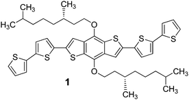 | ||
| Scheme 1 Structure of the (S)-3,7-dimethyl-1-octyl-functionalised BDT-based oligothiophene 1 synthesized in this work. | ||
Electronic circular dichroism (ECD) provides a very convenient way to characterize thin films of chiral π-conjugated molecules, because it responds sensitively to supramolecular chirality and for this reason it can selectively reveal ordered aggregated forms. Very recently, we used localized ECD spectroscopy, i.e. a CD-imaging dubbed CDi,40 to achieve the imaging of local domains with a different order in thin films of chiral π-conjugated polymers.41
The crude signal resulting from a common ECD spectropolarimeter is the sum of various contributions, which can be well accounted for and disentangled by applying Mueller matrix analysis.42 The leading terms of the ECD signal recorded for an anisotropic sample are:43
CDtot ≈ CDtrue + 1/2(LD′·LB + LD·LB′) + (LD·sin![[thin space (1/6-em)]](https://www.rsc.org/images/entities/char_2009.gif) α + LB)·cos α + LB)·cos![[thin space (1/6-em)]](https://www.rsc.org/images/entities/char_2009.gif) 2θ + … 2θ + … | (1) |
Things are very different for the second term in eqn (1), namely 1/2(LD′·LB + LD·LB′), because it is invariant upon sample rotation and, more importantly, it is completely independent of instrumental faults or by the intrinsic limitation of polarization-modulation measurements, as it is known in the context of chiral nematic systems.45 Its peculiarity consists in the fact that by flipping the sample by 180° with respect to the light axis, it becomes exactly inverted. Because it will be the focus of our further discussion, we shall call it simply LDLB.
In our own experience, in most cases, films of π-conjugated polymers or oligomers prepared by spin coating or drop-casting and after thermal or solvent annealing do not display severe artifacts, due to macroscopic anisotropies. The absence of macroscopic LD and LB is a direct consequence of the lack of a preferential orientation of the sample.
On the contrary, all the thin films of 1 revealed a strong LDLB effect, which called for an in-depth investigation.
Results and discussion
Synthesis of the (S)-3,7-dimethyl-1-octyl-functionalised BDT-based oligothiophene 1
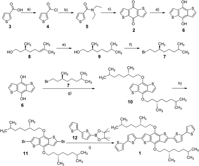
The complete synthetic pathway of the (S)-3,7-dimethyl-1-octyl-functionalised BDT-based oligothiophene 1 developed in this work is shown in Scheme 2.First of all, benzo[1,2-b:4,5-b′]dithiophene-4,8-dione (2) was synthesized following a literature procedure:24 commercial 3-thiophenecarboxylic acid (3) was converted into the corresponding acid chloride 4 by reaction with oxalyl chloride, followed by treatment with N,N-diethylamine to afford the intermediate amide 5, which was then cyclo-dimerized by means of n-BuLi to form 2 with good yield (77%). The latter was reduced to the corresponding diol 6 using NaBH4 in EtOH (71% yield); it is worth noticing that the subsequent work-up was only possible under acidic conditions, because neutral or alkaline environments led to the isolation of the starting dione 2. (S)-3,7-Dimethyl-1-bromooctane (7) was synthesized by Pd-catalysed hydrogenation of commercial (S)-(−)-β-citronellol (8) and following bromination of the resulting alcohol 9 with PPh3 and NBS.46
The benzo[1,2-b:4,5-b′]dithiophen-4,8-diol (6) was then alkylated through nucleophilic substitution with a slight excess of the chiral bromide 7 in heterogeneous conditions (K2CO3 and acetonitrile), affording the corresponding dialkylated product 10 (88% yield), which was subsequently brominated to give 2,6-dibromo-4,8-bis(((S)-3,7-dimethyloctyl)oxy)benzo[1,2-b:4,5-b′]dithiophene (11); this reaction was performed under alkaline conditions with n-BuLi and CBr4, since a preliminary bromination test of 10 in acidic conditions (NBS in CHCl3) unfortunately afforded the precursor 2 as the main product. Finally, the Suzuki–Miyaura coupling of 11 with an excess of the commercial boronic ester 12, performed under optimised conditions (Pd(PPh3)4, K2CO3, Ag2O, 1,4-dioxane, 70 °C), yielded the desired BDT-based oligothiophene 1 (30% yield).
Following exactly the same procedure, but on a smaller scale, we prepared the enantiomeric compound ent-1, starting from the non-natural isomer (R)-(+)-β-citronellol.
Optical and chiroptical properties of the (S)-3,7-dimethyl-1-octyl-functionalised BDT-based oligothiophene 1
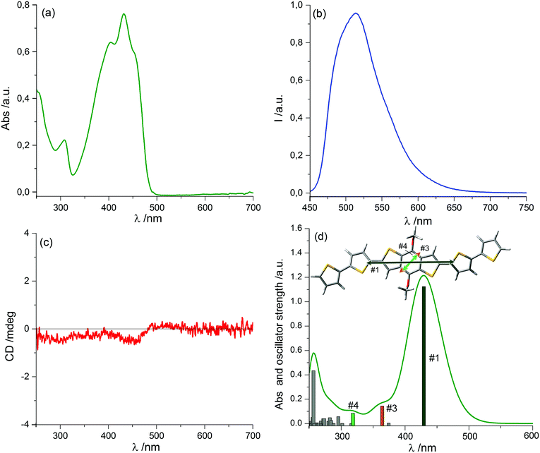
Spectroscopic characterization of the chiral oligothiophene 1 was first conducted in solution, recording UV-Vis absorption, fluorescence and ECD spectra in a “good” solvent such as chloroform (Fig. 1).The absorption spectrum showed a prominent broad band between 330 and 500 nm, with an evident vibronic structure and a maximum centred at 432 nm (molar extinction coefficient ε = 53![[thin space (1/6-em)]](https://www.rsc.org/images/entities/char_2009.gif) 000 M−1 cm−1), related to the π–π* transition of dialkyloxy-functionalized BDT-based oligothiophenes.47 A simulation of the absorption profile run with time-dependent density functional theory (TDDFT) at the CAM-B3LYP/TZVP level (including a solvent model for chloroform, see the ESI† for details) revealed the presence of three distinct transitions in the range between 270 and 500 nm. Of these, the first and strongest one at 430 nm is long-axis polarized, while the other two at shorter wavelengths are both tilted by ≈50° with respect to the long axis (Fig. 1d). This is relevant to interpret LD signals, as discussed below.
000 M−1 cm−1), related to the π–π* transition of dialkyloxy-functionalized BDT-based oligothiophenes.47 A simulation of the absorption profile run with time-dependent density functional theory (TDDFT) at the CAM-B3LYP/TZVP level (including a solvent model for chloroform, see the ESI† for details) revealed the presence of three distinct transitions in the range between 270 and 500 nm. Of these, the first and strongest one at 430 nm is long-axis polarized, while the other two at shorter wavelengths are both tilted by ≈50° with respect to the long axis (Fig. 1d). This is relevant to interpret LD signals, as discussed below.
The emission spectrum (excited at 382 nm) displayed a broad band between 450 and 650 nm, with a maximum around 513 nm and a long-wavelength tailing; therefore, this system showed quite a large Stokes shift (81 nm), with a quantum yield of 28%. The ECD spectrum was very weak and had dissymmetry factors g (defined as Δε/ε) always <10−4, indicating that the perturbation exerted on the intrinsically achiral chromophore of 1 by individual chirality centres of the alkyl chains is very small in isolated molecules.48–55
Since it is well-known that, upon addition of a proper non-solvent to a perfectly dissolved sample, π-conjugated polymers and oligomers form supramolecular aggregates in solution (which are expected to mimic the solid-state organization),14,20–22 we recorded UV-Vis absorption and ECD spectra of 1 in various solvent mixtures, composed of CHCl3 as a “good” solvent and n-hexane, cyclohexane, toluene, ethyl acetate, methanol or ethanol as “poor” solvents (see Fig. S1 in ESI†). Unfortunately, in all cases they showed only negligible differences with the spectra recorded in pure chloroform and no evident relation between the spectral profile and the increasing non-solvent concentration could be found. Therefore, these results revealed that 1 would not undergo aggregation in solution but it directly precipitates in the presence of >95 vol% of “bad” solvent, preventing further investigation.
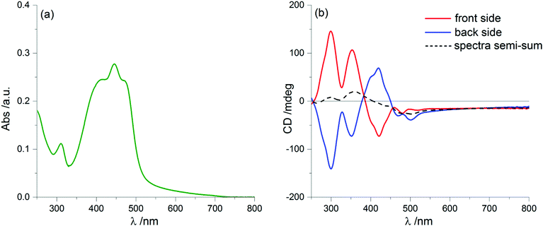
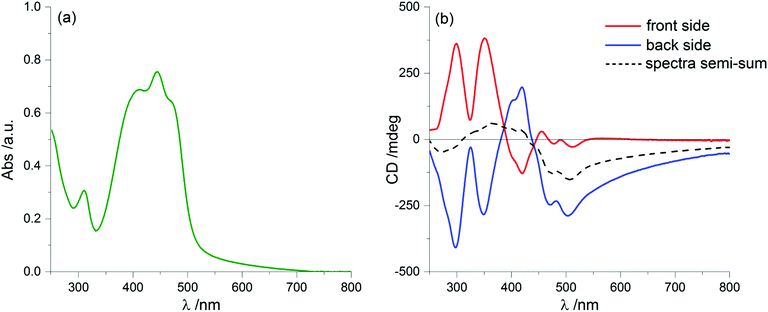
We prepared thin film samples of 1 by drop casting, i.e. depositing on a quartz plate about 100 μL of a 10−2 M solution of 1 in CHCl3, followed by slow evaporation of the solvent in an atmosphere saturated with CHCl3 vapours. The UV-Vis absorption spectrum of the thin film (Fig. 2a) showed a profile roughly comparable to the one observed in solution: the main bands fell between 350 nm and 500 nm, with a maximum at around 444 nm; furthermore, at long wavelengths a pronounced baseline drift was observed, due to scattering phenomena, which are common in solid samples.
Switching to the chiroptical characterization, we observed a totally different situation from the solution state: in fact, the ECD spectrum of the thin film (Fig. 2b, red line) revealed a very complex profile, consisting of a pair of weak negative bands around 520 and 470 nm and three strong bands, with maximum intensity at 420 nm (g = −7.6 × 10⁻³), 351 nm (g = 1.3 × 10⁻²) and 299 nm (g = 1.8 × 10⁻²) respectively, together with a long-wavelength tail allied to sample scattering. The anisotropy g-factors are noticeably large. Consistent profiles were obtained by recording ECD spectra at different rotation angles θ of the sample around the optical axis (horizontal) (Fig. S2 in ESI†). This suggested an almost negligible contribution of the third term in eqn (1), as expected from the fact that the sample was obtained by drop-casting and cannot display any preferential orientation in any direction parallel to the glass surface. On the contrary, by flipping the sample, i.e. by turning it by 180° with respect to the vertical axis, we observed an almost mirror image spectrum to the previous one (Fig. 2b, blue line), with two negative bands centred at 299 nm (g = −1.9 × 10⁻²) and 351 nm (g = −1.1 × 10⁻²), and a positive band at 420 nm (g = 7.7 × 10⁻³). Therefore, the thin film of our BDT-based oligothiophene 1 represents a rare example of an isotropic sample, undergoing (almost) complete reversal of the ECD signals upon switching the face of the thin film directed toward the incident light. The phenomenon is fully reproducible and was replicated for 5 separate samples, obtaining in each case identical results, including identical shapes and signs of the apparent ECD spectrum, and identical inversion upon flipping (Fig. 3).
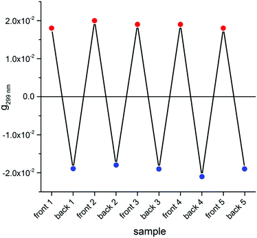 | ||
| Fig. 3 Dissymmetry g-factor values at 299 nm recorded for the front and the back side of 5 distinct freshly prepared thin films of compound 1. | ||
As a further control experiment, we synthesized the enantiomeric compound (R)-3,7-dimethyl-1-octyl-functionalised BDT-based oligothiophene ent-1 starting from unnatural (R)-(+)-β-citronellol, following the same pathway shown in Scheme 2. The thin film ECD spectrum of ent-1 revealed the same phenomenon of ECD inversion by sample flipping, but with a mirror-image behaviour compared to 1 (Fig. S3, ESI†): for the front side of the sample, we observed two negative bands centred at 299 nm and 351 nm. In addition, thin films obtained by drop casting of a solution containing equimolar amounts of 1 and ent-1 (i.e., a racemic mixture), led to very weak ECD signals (Fig. S5, ESI†). These findings demonstrate that 1 and ent-1 behave exactly as expected for a couple of enantiomers, whatever the source of the ECD signals of the thin films.
To understand the origin of ECD spectra, we must consider the various terms in eqn (1). True circular dichroism (CDtrue) is independent of sample orientation, while the LDLB effect (second term in eqn (1)), dominates the chiroptical response to such a large extent to produce the uncommon g-factors mentioned above.
Since we can discard a role for the third term in eqn (1), the chiroptical signal can be considered the sum of CDtrue, independent of sample orientation, and LDLB, which inverts upon sample flipping. Thus, if we take the average (semi-sum) of the two ECD spectra of 1 for the sample “back” or “front” to the light source, we isolate the genuine ECD contribution, as depicted in Fig. 2b (black dashed line). Once again, the semi-sum spectrum of ent-1 (Fig. S3, ESI†) turns out to be the mirror image of the same spectrum of 1.
Artifacts due to LD or LB are quite common in solid-state ECD spectra, when the sample presents a desirable or even an unwanted anisotropy, which occurs for example for stretched films.56 On the contrary, the LDLB effect with the associated ECD inversion appears unusual: in fact, to the best of our knowledge, it was reported before for chiral nematics, crystalline samples and notably for an achiral polyvinyl alcohol (PVA) film dyed with the achiral azo-compound Congo Red and highly stretched in order to make it macroscopically anisotropic.44 In such a case, the onset of a LDLB term cannot be regarded as surprising: the Congo red molecules are definitely oriented and they surely display very large LD, while the stretched PVA film itself will definitely be birefringent.
Our BDT-based oligothiophene 1 films, instead, were prepared by drop casting, without any other operation which may impart a preferential molecular orientation. Thus, we have negligible total 〈LD〉 and 〈LB〉, i.e. the macroscopic quantities averaged over the whole film. This is demonstrated by the invariance of the CD signal with respect to sample rotation around the incident light direction (angle θ in eqn (1)).
Because
| 〈LD〉 = 〈LB〉 = 0 | (2) |
| 〈LD·LB′〉 + 〈LD′·LB〉 ≠ 0 | (3) |
(1) there are ordered domains where both linear properties do not vanish;
(2) in all or at least a majority of these domains, the product LD·LB′ (or equivalently LD′·LB) is of one sign, in order to prevent cancellation over the whole sample;
(3) because the prime indicates a +45° angle between the axes where LD and LB are referred, from the point of view of incident light, then this property is a manifestation of (supra)molecular chirality.
The situation is pictorially represented in Fig. 4.
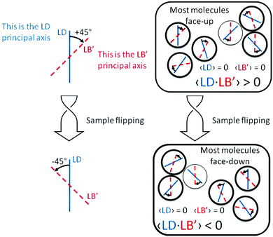 | ||
| Fig. 4 Schematic representation of the properties of the term LD·LB′ responsible for the sign inversion of the ECD spectrum shown in Fig. 2b. | ||
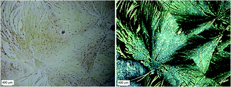
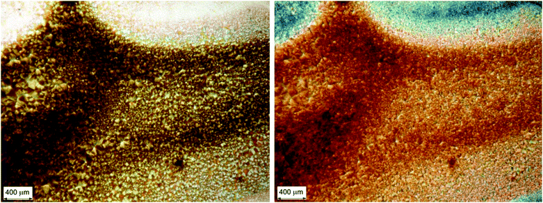
The occurrence of locally anisotropic and linearly birefringent domains is made evident by observing a thin film by means of a microscope with crossed linear polarisers, as shown in Fig. 5. We can immediately notice that strongly birefringent spheroidal microdomains (diameter < 500 μm) stand out on a black background (i.e. with no LB).
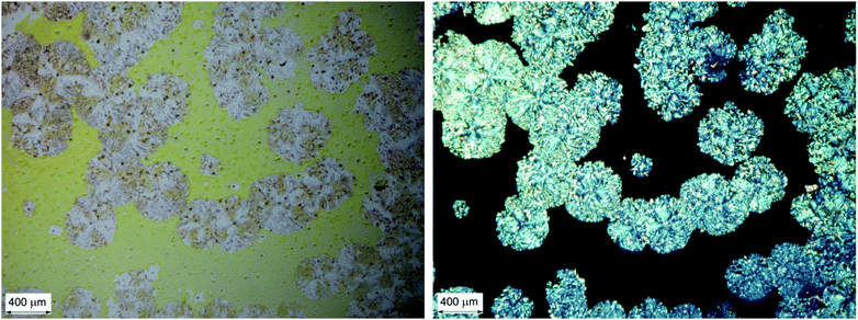 | ||
| Fig. 5 Optical microscopy images of a chiral BDT-based oligothiophene 1 thin film sample: micrograph with non-polarized light (left); micrograph under cross-polarized filters (right). | ||
By assuming that at least the first-level aggregates feature some alignment between conjugated BDT moieties packed with each other, the LD term is directly related to the polarization of the corresponding transition. In fact, the sequence of signs observed in Fig. 2 (blue or red traces) is in accordance with the fact that the transition above 400 nm (#1 in Fig. 1d) has different polarization with respect to the two transitions below 400 nm (#3 and #4, in Fig. 1d), as demonstrated by TDDFT calculations. Assuming that LB remains of the same sign over a wider region, this simple reasoning accounts for the opposite signs of the strong transitions at 430 nm on one side and 380/300 nm on the other.
In order to better explain the situation, we can resort to a pictorial similarity. Our chromophore is flat just like any letter written on a glass surface. However, some letter like “p” would read “q” if watched through the glass. Indeed “p” and “q” are related by a mirror plane in two dimensions and can be considered 2-D enantiomers. If we cast a handful of “p”s onto a surface, they will randomly fall face-up or face-down and we'd obtain a 2-D racemate, i.e. an equal mixture of “p” and “q” which reads equally when watched from the two sides of the glass. In order to consistently have an excess of “p” from one side (viz. of “q” from the other), the two faces of the letter must be different: in such a way, the chance of landing face-up or face-down would be different. We may say that the two faces, which in principle are enantiotopic, must become diastereotopic. This is only made possible by a chiral element, which in the present case is provided by the branched alkyl chains.
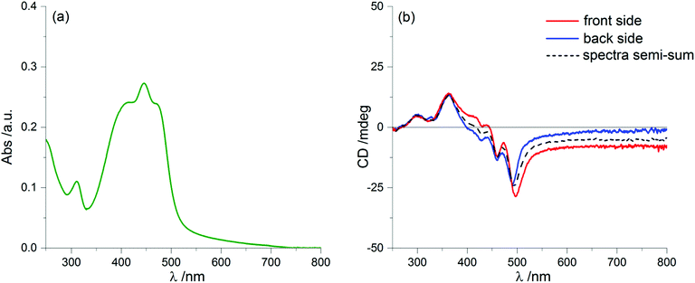
A further puzzling aspect comes from solvent annealing, a common procedure to obtain more homogeneous samples of thin films. If we let the samples stand for a few minutes (up to about 15′) in a chamber saturated with vapours of a “good” solvent (CHCl3), we obtain the ECD spectra displayed in Fig. 6, which are (almost) invariant upon sample rotation (see Fig. S7 in ESI†) and also upon flipping. Again, this has been repeatedly observed on up to 5 separate samples. This invariance guarantees that the spectrum is now fully LDLB effect-free and must be regarded as a genuine ECD. The intensity of the ECD signals is apparently reduced compared to those found on the freshly prepared samples. This can be explained by a simple comparison: the two dashed lines of Fig. 2 and 6 match almost perfectly (positions, signs and also amplitudes of the bands). Thus, the average spectrum found by taking the semi-sum of the two orientations for the original film is identical to the “true ECD” observed for the solvent-annealed film. This means that, in spite of the strong ECD signals due to the LDLB term, we may confirm that the semi-sum spectrum is a real representation of a genuine ECD.
This spectacular change in the ECD spectrum is associated with no significant changes in the UV-Vis absorption spectrum compared to the non-annealed film (Fig. 6a), although with a different morphology of the thin film: in fact, optical microscopy images (Fig. 7) display a more homogeneous texture, as if the small domains had melted and smeared into weakly birefringent “palm leaf-like” domains, suggestive of a nematic texture, although it is devoid of any significant LDLB effect.
By further exposure to the solvent vapours, we expected that the same process would proceed further, but on the contrary after 60 minutes of annealing we found again a clear LDLB effect similar to that measured on the freshly prepared sample: once more we recorded almost mirror-image profiles by sample flipping, as shown in Fig. 8b. Again, taking the semi-sum of the two spectra left a small residual signal (dashed line of Fig. 8b) which resembles the dashed lines of Fig. 2b and 6b.
What is really remarkable is that the dichroic signal is much stronger and consequently we also record higher g-factors, approaching values as large as 0.05 (more precisely it is 4.8 × 10⁻² at 351 nm). This value is extraordinarily large for a purely organic system.
Optical microscopy investigation (Fig. 9) on the fully solvent-annealed film revealed a highly homogeneously birefringent structure, where no local structure can be recognized. No further significant changes in spectroscopic and morphological properties were observed with longer annealing times.
It is clear that in all cases investigated, there is a constant background of a genuine ECD signature. This cannot be a property of isolated molecules, because we had found before that in solution 1 displays vanishing ECD. It must be the result of a well-defined chiral supramolecular structure, featuring a twisted stack with negative helicity of the long molecular axis, on account of the signs of the ECD spectrum (with reference to the dashed lines in Fig. 2b, 6b and 8b).57 This means that at least the first level of hierarchy, which normally dominates the appearance of the ECD spectrum of supramolecular aggregates,58 seems to be preserved among all investigated films, and is almost unaffected by annealing. Solvent annealing has instead a strong impact on the organization at the mesoscopic level, as detected by optical microscopy. This is a rather unique case, in which the apparent ECD signal does suggest the occurrence of a complex aggregation pathway, but a more accurate analysis reveals the presence of a major first-order supramolecular aggregate characterized by a specific ECD signature. It is remarkable that this occurs only in the films upon solvent exposure, while in solution the molecules remain completely solvated until they precipitate.
The final schematic picture that may fit all the phenomena discussed so far is shown in Fig. 10, where we exploit the above mentioned similarity with “p”/”q” enantiomerism in 2-D. Upon drop-casting, the molecules adhere on quartz preferentially on one face, let's say “p”, because of intrinsic molecular chirality. Thereupon, they pack on top of each other in a helical stack with negative twist, possibly forming in a chiral nematic phase. The ECD signal results from the sum of true ECD (CDtrue) and the LDLB term (eqn (1)). The former is invariant, the latter is inverted upon sample flipping (“p” transforms into “q”), Fig. 2b. Short time exposure to the solvent detaches these helices from the surface, which leads to their random orientation: they remain left-handed helices, but they expose both “p” and “q” faces to the light which leads to cancellation of the LDLB effect (while CDtrue is conserved), Fig. 6b. Finally, a longer annealing lets the molecules find their most stable configuration on the surface re-establishing the predominance of “p” and restoring a large LDLB term, Fig. 8b.
Conclusions
Our chiral benzodithiophene derivative 1 displays an uncommon feature which leads to a very strong dichroism, with g-factor values of almost 0.05, which is extraordinary for small organic molecules and only arises thanks to a remarkable supramolecular order. The origin of these strong signals stems from a LDLB effect, and as a consequence it completely inverts upon changing the direction of illumination: if light comes from the front or from the back of the sample, its chiroptical response will be opposite. This property, associated with the very strong g-value will be valuable for the conception of novel optoelectronic devices sensitive to the position of the light source.59,60Acknowledgements
Ministero per l'Istruzione, l'Università e la Ricerca (PRIN 2012A4Z2RY) and Università di Pisa (PRA 2015_38, PRA 2016_50 and PRA 2017_28) are gratefully acknowledged for funding. The authors acknowledge the help of Mr Lorenzo Portus in the synthesis of ent-1.References
- F. J. M. Hoeben, P. Jonkheijm, E. W. Meijer and A. P. H. J. Schenning, Chem. Rev., 2005, 105, 1491–1546 CrossRef CAS PubMed.
- P. M. Beaujuge and J. M. J. Fréchet, J. Am. Chem. Soc., 2011, 133, 20009–20029 CrossRef CAS PubMed.
- Z. B. Henson, K. Mullen and G. C. Bazan, Nat. Chem., 2012, 4, 699–704 CrossRef CAS PubMed.
- T.-Q. Nguyen, V. Doan and B. J. Schwartz, J. Chem. Phys., 1999, 110, 4068–4078 CrossRef CAS.
- J. Kim and T. M. Swager, Nature, 2001, 411, 1030–1034 CrossRef CAS PubMed.
- X. T. Hao, T. Hosokai, N. Mitsuo, S. Kera, K. K. Okudaira, K. Mase and N. Ueno, J. Phys. Chem. B, 2007, 111, 10365–10372 CrossRef CAS PubMed.
- T. L. Andrew and T. M. Swager, J. Polym. Sci., Part B: Polym. Phys., 2011, 49, 476–498 CrossRef CAS.
- L. Pu, Acta Polym., 1997, 48, 116–141 CrossRef CAS.
- A. Rajca and M. Miyasaka, in Functional Organic Materials, ed. T. J. J. Müller and U. H. F. Bunz, Wiley-VCH, Weinheim, Germany, 2007, pp. 547–581 Search PubMed.
- L. A. P. Kane-Maguire and G. G. Wallace, Chem. Soc. Rev., 2010, 39, 2545–2576 RSC.
- M. Verswyvel and G. Koeckelberghs, Polym. Chem., 2012, 3, 3203–3216 RSC.
- J. Cornil, D. Beljonne, J.-P. Calbert and J.-L. Brédas, Adv. Mater., 2001, 13, 1053–1067 CrossRef CAS.
- S. Zahn and T. M. Swager, Angew. Chem., Int. Ed., 2002, 41, 4225–4230 CrossRef PubMed.
- G. Pescitelli, O. H. Omar, A. Operamolla, G. M. Farinola and L. Di Bari, Macromolecules, 2012, 45, 9626–9630 CrossRef CAS.
- L. Torsi, G. M. Farinola, F. Marinelli, M. C. Tanese, O. H. Omar, L. Valli, F. Babudri, F. Palmisano, P. G. Zambonin and F. Naso, Nat. Mater., 2008, 7, 412–417 CrossRef CAS PubMed.
- S. M. Jeong, Y. Ohtsuka, N. Y. Ha, Y. Takanishi, K. Ishikawa, H. Takezoe, S. Nishimura and G. Suzaki, Appl. Phys. Lett., 2007, 90, 211106 CrossRef.
- Y. Yang, R. C. da Costa, D.-M. Smilgies, A. J. Campbell and M. J. Fuchter, Adv. Mater., 2013, 25, 2624–2628 CrossRef CAS PubMed.
- Y. Yang, R. C. da Costa, M. J. Fuchter and A. J. Campbell, Nat. Photonics, 2013, 7, 634–638 CrossRef CAS.
- X. Shang, I. Song, H. Ohtsu, Y. H. Lee, T. Zhao, T. Kojima, J. H. Jung, M. Kawano and J. H. Oh, Adv. Mater., 2017, 29, 1605828 CrossRef PubMed.
- C. Resta, S. Di Pietro, M. Majerić Elenkov, Z. Hameršak, G. Pescitelli and L. Di Bari, Macromolecules, 2014, 47, 4847–4850 CrossRef CAS.
- C. Resta, G. Pescitelli and L. Di Bari, Macromolecules, 2014, 47, 7052–7059 CrossRef CAS.
- F. Babudri, D. Colangiuli, L. Di Bari, G. M. Farinola, O. Hassan Omar, F. Naso and G. Pescitelli, Macromolecules, 2006, 39, 5206–5212 CrossRef CAS.
- Y. Liu, X. Wan, F. Wang, J. Zhou, G. Long, J. Tian and Y. Chen, Adv. Mater., 2011, 23, 5387–5391 CrossRef CAS PubMed.
- J. Hou, M.-H. Park, S. Zhang, Y. Yao, L.-M. Chen, J.-H. Li and Y. Yang, Macromolecules, 2008, 41, 6012–6018 CrossRef CAS.
- L. Huo, J. Hou, H.-Y. Chen, S. Zhang, Y. Jiang, T. L. Chen and Y. Yang, Macromolecules, 2009, 42, 6564–6571 CrossRef CAS.
- C. Gao, L. Wang, X. Li and H. Wang, Polym. Chem., 2014, 5, 5200–5210 RSC.
- M. Li, W. Ni, X. Wan, Q. Zhang, B. Kan and Y. Chen, J. Mater. Chem. A, 2015, 3, 4765–4776 CAS.
- Y. Liu, C.-C. Chen, Z. Hong, J. Gao, Y. Yang, H. Zhou, L. Dou, G. Li and Y. Yang, Sci. Rep., 2013, 3, 3356 CrossRef PubMed.
- B. Kan, Q. Zhang, M. Li, X. Wan, W. Ni, G. Long, Y. Wang, X. Yang, H. Feng and Y. Chen, J. Am. Chem. Soc., 2014, 136, 15529–15532 CrossRef CAS PubMed.
- J. Zhou, X. Wan, Y. Liu, Y. Zuo, Z. Li, G. He, G. Long, W. Ni, C. Li, X. Su and Y. Chen, J. Am. Chem. Soc., 2012, 134, 16345–16351 CrossRef CAS PubMed.
- S. Shen, P. Jiang, C. He, J. Zhang, P. Shen, Y. Zhang, Y. Yi, Z. Zhang, Z. Li and Y. Li, Chem. Mater., 2013, 25, 2274–2281 CrossRef CAS.
- A. Cho and E. Lim, Mol. Cryst. Liq. Cryst., 2014, 598, 92–96 CrossRef CAS.
- Y. Lin, L. Ma, Y. Li, Y. Liu, D. Zhu and X. Zhan, Adv. Energy Mater., 2014, 4, 1300626 CrossRef.
- Q. Fan, M. Li, P. Yang, Y. Liu, M. Xiao, X. Wang, H. Tan, Y. Wang, R. Yang and W. Zhu, Dyes Pigm., 2015, 116, 13–19 CrossRef CAS.
- B. Kan, Q. Zhang, F. Liu, X. Wan, Y. Wang, W. Ni, X. Yang, M. Zhang, H. Zhang, T. P. Russell and Y. Chen, Chem. Mater., 2015, 27, 8414–8423 CrossRef CAS.
- B. Qiu, J. Yuan, X. Xiao, D. He, L. Qiu, Y. Zou, Z.-g. Zhang and Y. Li, ACS Appl. Mater. Interfaces, 2015, 7, 25237–25246 CAS.
- A. Tang, C. Zhan and J. Yao, Chem. Mater., 2015, 27, 4719–4730 CrossRef CAS.
- H. Wei, W. Chen, L. Han, T. Wang, X. Bao, X. Li, J. Liu, Y. Zhou and R. Yang, Chem. – Asian J., 2015, 10, 1791–1798 CrossRef CAS PubMed.
- T. Wang, L. Han, H. Wei, D. Zhu, X. Bao, S. Qiao, W. Sun, W. Chen and R. Yang, J. Mater. Chem. A, 2016, 4, 8784–8792 CAS.
- K. Claborn, E. Puklin-Faucher, M. Kurimoto, W. Kaminsky and B. Kahr, J. Am. Chem. Soc., 2003, 125, 14825–14831 CrossRef CAS PubMed.
- F. Zinna, C. Resta, M. Górecki, G. Pescitelli, L. Di Bari, T. Jávorfi, R. Hussain and G. Siligardi, Macromolecules, 2017, 50, 2054–2060 CrossRef CAS.
- Y. Shindo, Opt. Eng., 1995, 34, 3369–3384 CrossRef CAS.
- R. Kuroda and T. Harada, in Comprehensive Chiroptical Spectroscopy, ed. N. Berova, P. L. Polavarapu, K. Nakanishi and R. W. Woody, John Wiley & Sons, Inc., Hoboken, New Jersey, USA, 2012, pp. 91–113 Search PubMed.
- R. Kuroda, T. Harada and Y. Shindo, Rev. Sci. Instrum., 2001, 72, 3802–3810 CrossRef CAS.
- Y. Shindo and Y. Ohmi, J. Am. Chem. Soc., 1985, 107, 91–97 CrossRef CAS.
- R. van Hameren, A. M. van Buul, M. A. Castriciano, V. Villari, N. Micali, P. Schön, S. Speller, L. Monsù Scolaro, A. E. Rowan, J. A. A. W. Elemans and R. J. M. Nolte, Nano Lett., 2008, 8, 253–259 CrossRef CAS PubMed.
- E. Lim, S. Lee and K. K. Lee, J. Nanosci. Nanotechnol., 2012, 12, 4243–4247 CrossRef CAS PubMed.
- B. M. W. Langeveld-Voss, R. A. J. Janssen and E. W. Meijer, J. Mol. Struct., 2000, 521, 285–301 CrossRef CAS.
- S. C. J. Meskers, E. Peeters, B. M. W. Langeveld-Voss and R. A. J. Janssen, Adv. Mater., 2000, 12, 589–594 CrossRef CAS.
- C. J. Collison, L. J. Rothberg, V. Treemaneekarn and Y. Li, Macromolecules, 2001, 34, 2346–2352 CrossRef CAS.
- J. N. Wilson, W. Steffen, T. G. McKenzie, G. Lieser, M. Oda, D. Neher and U. H. F. Bunz, J. Am. Chem. Soc., 2002, 124, 6830–6831 CrossRef CAS PubMed.
- M. R. Craig, P. Jonkheijm, S. C. J. Meskers, A. P. H. J. Schenning and E. W. Meijer, Adv. Mater., 2003, 15, 1435–1438 CrossRef CAS.
- A. Satrijo, S. C. J. Meskers and T. M. Swager, J. Am. Chem. Soc., 2006, 128, 9030–9031 CrossRef CAS PubMed.
- Y. Wang, T. Sakamoto and T. Nakano, Chem. Commun., 2012, 48, 1871–1873 RSC.
- X. Yang, S. Seo, C. Park and E. Kim, Macromolecules, 2014, 47, 7043–7051 CrossRef CAS.
- E. Castiglioni, P. Biscarini and S. Abbate, Chirality, 2009, 21, E28–E36 CrossRef CAS PubMed.
- D. Padula, F. Santoro and G. Pescitelli, RSC Adv., 2016, 6, 37938–37943 RSC.
- G. Pescitelli, L. Di Bari and N. Berova, Chem. Soc. Rev., 2014, 43, 5211–5233 RSC.
- H. Wang, T. Luo, H. Song and J. B. Christen, Opt. Lett., 2013, 38, 4554–4557 CrossRef PubMed.
- H. Song, Z. Lu, T. Luo, J. B. Christen and H. Wang in 2014 27th IEEE International System-on-Chip Conference (SOCC), Las Vegas, NV, 2014, pp. 58–62.
Footnote |
| † Electronic supplementary information (ESI) available: Detailed experimental procedures; computational details; UV-Vis absorption and ECD spectra of ent-1 and racemic 1 as thin films; 1H-NMR and 13C-NMR spectra of all synthesized products. See DOI: 10.1039/c7qm00233e |
| This journal is © the Partner Organisations 2017 |

