Interfacial solar heating by self-assembled Fe3O4@C film for steam generation†
Rong
Chen
a,
Kehang
Zhu
a,
Qimao
Gan
a,
Yongqiang
Yu
a,
Tuqiao
Zhang
a,
Xiaowei
Liu
a,
Miaomiao
Ye
 *a and
Yadong
Yin
 *ab
*ab
aZhejiang Key Laboratory of Drinking Water Safety and Distribution Technology, Zhejiang University, Hangzhou, 310058, P. R. China. E-mail: yemiao008@zju.edu.cn
bDepartment of Chemistry, University of California, Riverside, CA 92521, USA. E-mail: yadong.yin@ucr.edu
First published on 10th October 2017
Abstract
Hydrophobic Fe3O4@C core–shell nanostructures are developed as the solar-thermal materials for air–water interfacial solar heating for steam generation. The Fe3O4@C core–shell nanostructures can self-assemble into a thin film at the air–water interface, which benefits their full utilization for light absorption and heat transfer. When needed, the Fe3O4@C thin film can be separated from water within 20 seconds by applying an external magnetic field. Removing the external magnetic field allows rapid reassembly of the nanostructures within a second. Such efficient separation of the light absorbers and their reformation as a thin film is beneficial to practical applications where recycling and reuse of the light absorbers are critically important. In order to evaluate their practicability for interfacial solar heating, we systematically study the water evaporation efficiency, water quality of the condensed vapor, and chemical durability of this new Fe3O4@C nanostructures. It is found that the water evaporation efficiency of the floating Fe3O4@C film can reach 1.07 kg m−2 h−1 under a solar intensity of 1 kW m−2, which is significantly higher than the case of uniform dispersion of Fe3O4@C nanostructures in water.
Introduction
Seawater desalinization is considered as one of the most promising techniques to tackle the global water crisis since it has the potential to offer abundant high-quality water.1,2 In practice, two methods are widely used for water desalination, including the membrane-based separation process and the distillation method.3,4 As the distillation method consumes more energy, it is being gradually replaced by the membrane-based process, although both are considered to be energy intensive.5 The required energy comes from the combustion of fossil fuels such as oil and gas, which leads to large carbon footprints, and causes ozone depletion and global warming. To reconsider the distillation method as a viable option, it is required to promote the water evaporation efficiency in seawater desalination and utilize alternative energy sources such as solar energy for heating. As water evaporation only occurs at the air–water interface, it is rational to place the heating elements at the air–water interface. If the heating elements can absorb solar light and efficiently convert the energy into heat, then it becomes a promising green approach that may greatly increases the efficiency of water evaporation by avoiding the need of heating bulk water as in the conventional desalination processes.6,7 This conceptually new process has recently retriggered considerable research interests toward seawater distillation.To date, carbon materials,8–23 plasmonic metal nanoparticles,24–32 and some metallic oxides7,33–35 have been used as the light absorbers and solar-thermal conversion materials for solar steam generation. Among them, carbon-based materials such as graphene,8,11–16 hollow carbon spheres,17,18 carbon nanotube,20 graphite,21 have recently attracted more attentions because of their high solar thermal efficiency, excellent chemical stability, and low cost. However, nanosized carbon materials are difficult to separate from seawater, resulting in loss of the active materials and more importantly, significant water pollution. Although immobilization of such materials on some supporting substrates may improve material recycling, it often decreases the evaporation efficiency. Also, some supports such as airlaid paper and gauze cannot ensure close contact with the water surface, resulting in inadequate utilization of the solar-thermal materials.10,12,32 Moreover, these supports may decay quickly over time under the working condition, leading to problems such as additional pollution and the detachment of solar-thermal materials.16,22
In this work, we report the synthesis of hydrophobic Fe3O4@C core–shell nanostructures as the solar-thermal conversion materials and their self-assembly into a thin film at the air–water interface for efficient solar steam generation. Unlike other supported solar-thermal materials, the Fe3O4@C thin film can spontaneously form at the air–water interface without the need of any additional support materials, and get close contact with the water surface to ensure efficient heat transfer. Furthermore, the Fe3O4@C film can be separated from the water surface within seconds by applying an external magnetic field and when needed, reassembled into a thin film also within a second, suggesting the possibility of efficient recycling. In addition to the fast separation and reformation, we also demonstrate the high water evaporation efficiency, minimal contamination to the condensed vapor, and high chemical durability of the assembled Fe3O4@C film, all of which are beneficial properties to their practical application in water desalination.
Experimental
Materials
Glucose (99%), sodium acetate anhydrous (NaAc, >99%), polyethylene glycol (PEG, >99%), ethylene glycol (EG, >99%), ethanol (97%), n-hexane (97%) were analytical grade and obtained from Sinopharm Chemical Reagent Co, China. Iron(III) chloride (FeCl3, 97%) and 1H,1H,2H,2H-perfluorooctyltrichloro silane (PFOTS, 97%) were purchased from Sigma-Aldrich, USA. All chemicals were used as received without further purification.Preparation of the hydrophobic Fe3O4@C nanostructures
The Fe3O4 nanospheres were synthesized by a solvothermal method, which was reported previously with detailed characterization of their magnetic properties.36,37 Typically, FeCl3 (0.811 g, 5 mmol) was firstly dissolved in ethylene glycol (40 mL) to form a clear solution, followed by the addition of sodium acetate (3.6 g) and polyethylene glycol (1.0 g). The mixture was stirred vigorously for 2 h and transferred to a 50 mL Teflon-lined stainless-steel autoclave. The autoclave was heated at 200 °C for 8 h, and allowed to cool to room temperature. The products were washed with ethanol and water respectively for 3 times. Subsequently, 0.3 g of the as-prepared Fe3O4 nanospheres were mixed with 0.25 g, 0.5 g, 1.0 g, 2.0 g of glucose in 30 mL H2O to produce samples with coatings of different thicknesses. The suspension was sonicated for 30 min and transferred to a 50 mL Teflon-lined stainless steel autoclave. The autoclave was heated at 200 °C for 12 h, then cooled to room temperature. The black products (hydrophilic Fe3O4@C core–shell nanostructures) were washed with water for 5 times and then ethanol for 3 times. Finally, the as-prepared Fe3O4@C core–shell nanostructures were transferred into 4 mL n-hexane containing 0.5% PFOTS. The mixture was sonicated for 20 min and dried at 60 °C for 4 h, producing the hydrophobic Fe3O4@C core–shell nanostructures.Interfacial assembly of the Fe3O4@C film
The hydrophobic Fe3O4@C core–shell nanostructures were randomly dispersed on the surface of water followed by irradiation under a xenon lamp for 4 hours or by heating at 40 °C for 4 h. Subsequently, the Fe3O4@C nanostructures were collected by a magnet. After that, the container was refilled with distilled water. Finally, a thin film could be rapidly assembled upon removal of the magnet.Water evaporation
The water evaporation experiments were carried out at room temperature of 25 °C ± 1 °C and air humidity of 45%. A cylindrical glass with a diameter of 48 mm and depth of 100 mm were used as a container for water evaporation. A 300 W Xenon lamp (CEL-S500, 20A, Beijing Jin Yuan Science and Technology Co., China) was used with an AM 1.5 filter to simulate the solar light, and the aperture diameter was adjusted to be the same as the floating film. The light source was vertically fixed to the water surface at a distance of 5 cm. The light intensity at the water surface was ∼1000 W m−2, as measured by a laser power meter (LP-3A, Beijing Physcience Opto-Electronics, China). Infrared photographs were recorded with a thermal infrared imager (S65, FLIR America). The temperature of the water was monitored using a Type K-thermocouple and recorder (SSN-61, YUWESE China).Materials characterization and water quality detection
The morphologies of the samples were characterized by a JEM-2010 microscope at an accelerating voltage of 200 kV. The contact angles of the samples were measured by an OCA20 contact angle measuring device (Dataphysics, Germany). The ultraviolet visible near infrared (UV-Vis-NIR) diffuse reflectance spectra of the samples were measured on a UV-Vis-NIR spectrophotometer (U-4100, Hitachi Japan) equipped with an integrating sphere accessory. BaSO4 powder was used as a 100% reflectance standard. The specific heat capacity was determined by a differential scanning calorimeter (DSC 200F, NETZSCH Germany). The 3D optical microscope image was taken by Digital Microscope (VHX-700FC, Keyence Japan).Typical water-quality indexes were measured for evaluating the quality of the condensed water. The electrical conductivity (salinity) was measured by a conductivity meter (HQ14d, HACH America). The turbidity was measured by a portable turbidimeter (2100Q01, HACH America). The total organic carbon (TOC) was determined via a TOC analyzer (TOC-VCPH, Shimadzu Japan). The concentrations of anions were determined using an ionic chromatograph (DX120, Dionex America). The concentration of cations was determined using a PerkinElmer NexION 350Q ICP-MS Spectrometer.
Results and discussion
Characterization of the Fe3O4@C core–shell nanostructures
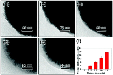
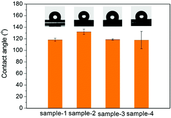
The TEM images of the as-prepared Fe3O4 nanospheres is shown in Fig. 1a. After coating with a carbon layer, a thin gray layer is formed outside of the Fe3O4 nanospheres. In order to explore the effect of the carbon layer thickness on the water evaporation efficiency, Fe3O4@C core–shell nanostructures were prepared by mixing 0.3 g of Fe3O4 nanospheres with 0.25 g, 0.5 g, 1.0 g, and 2.0 g of glucose, producing carbon coating of ∼4.0 nm, ∼8.1 nm, ∼13.0 nm, and ∼19.3 nm in thickness, respectively (Fig. 1f). Here we denote them as Sample-1, Sample-2, Sample-3, and Sample-4, correspondingly. Fig. 1 clearly suggests that the coating thickness gradually increases with the increasing addition of the glucose.The surface of the Fe3O4@C core–shell nanostructures was modified by PFOTS to enable hydrophobicity. The hydrophobicity of the products was characterized by measuring their water contact angles. For testing the wetting properties, the samples were pressed into a disc (the KBr pellet pressing method typically used for preparing IR samples). The water contact angles for Samples 1–4 are 118.2° ± 2.8°, 132.1° ± 4.5°, 118.7° ± 1.1°, and 118.0° ± 15°, respectively (Fig. 2), indicating hydrophobicity of their surfaces.
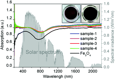
Fig. 3 shows the absorption spectra at the wavelength range from 200 to 2200 nm of the Fe3O4 nanospheres and Fe3O4@C core–shell nanostructures. Clearly, coating of a thin carbon layer significantly increases the intensities of the absorption spectra spanning from the ultraviolet (UV) to visible and infrared regions, along with the color change from brown to black (Fig. 3, inset). The increased solar absorption means that it can absorb and harvest more solar energy. Here, we calculate the proportion of light absorption in different spectrum regions according to the following equation by the mathematical integral:38
 | (1) |
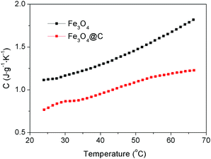
The specific heat capacity of a substance is the amount of energy needed to change the temperature of 1 kg of the substance by 1 °C. Different substances have different specific heat capacities. The lower the specific heat capacity, the stronger the heat absorption or heat dissipation of the substance. The specific heat capacities of the Fe3O4 nanospheres and Fe3O4@C core–shell nanostructures (Sample-2) were measured, with the results being shown in Fig. 4. The specific heat capacity of the Fe3O4@C core–shell nanostructures is lower than that of the Fe3O4 nanospheres at the temperatures range from 24 °C to 66.5 °C, indicating that the Fe3O4@C core–shell nanostructures possess better heat absorption capacity.
Self-assembly of the Fe3O4@C thin film
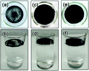
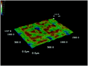
As discussed above, the formation of a thin film at the air–water interface will enable more efficient use the solar-thermal conversion material for light absorption and therefore avoid the need of heating the bulk water. As expected from the hydrophobic nature of the Fe3O4@C nanostructures, the surface tension of water drives their spreading on the water surface. We observed, however, more uniform assembly of these particles on water surface could be achieved by mild heating. As shown in Fig. 5a and b, adding the hydrophobic Fe3O4@C core–shell nanostructures to the water surface resulted in a thin film containing small clusters of the nanoparticles. Irradiation of such a film under a xenon lamp for 4 hours led to the disintegration of the large macroscopic agglomerates into microscale clusters and eventually a much more uniform film (Fig. 5c and d). The as-formed thin film was composed of small clusters Fe3O4@C core–shell nanostructures with sizes ranging from several to tens of micrometers, as shown in the SEM image in Fig. S1 (ESI†). We further characterized the film quality and thickness by recording the 3D optical microscopy image. Before observation, the Fe3O4@C film was prepared on a commercial silicon wafer by dip-coating method. Typically, a 1 cm × 1 cm silicon wafer was submerged beneath the Fe3O4@C floating film, then the silicon wafer was vertically pulled out of the water followed by drying at room temperature. The average thickness of the particular film measured was about 48.6 μm with the maximum thickness of 92 μm and a minimum thickness of 10.8 μm (Fig. 6). The same enhancement effect to the film uniformity can also be achieved by heating the original film at 40 °C for 4 h, as shown in Fig. 5e and f. We believe that the thermal motion of the solution is the key in assisting the surface tension in promoting the assembly of uniform nanoparticle film. Once formed, the Fe3O4@C film can be separated from water within 20 seconds by applying a magnetic field through a 3 cm × 2 cm × 1 cm cuboid NdFeB magnet. Upon removing the magnetic field, the particles can be reassembled into another floating film with the original quality on the water surface within a second, without the need of additional light irradiation or mild heating. We believe that such rapid separation and reformation of the nanoparticle film can benefit the recycling and reuse of these solar-thermal conversion materials in potential practical applications.Water evaporation
We further explored the performance of the thin films in water evaporation. Our study involved the film made by random deposition of the hydrophobic Fe3O4@C particles (Fig. 5a), the uniform film of self-assembled hydrophobic Fe3O4@C particles (Fig. 5c), and hydrophilic Fe3O4@C uniformly dispersed in water. As shown in Fig. 7, all water evaporation processes can be modeled by the zero-order kinetics and described by m − m0 = −kt, where m0 and m are the initial water mass and the actual water mass at time t respectively, and k the water evaporation efficiency. The zero-order kinetic equations and the water evaporation efficiencies (k) of the different processes were calculated in Table S2 (ESI†). The water evaporation efficiency of the self-assembled film of hydrophobic Fe3O4@C nanostructures is 1.07 kg m−2 h−1, which is 1.27, 1.21 and 2.26 times higher than that of the randomly deposited film, hydrophilic Fe3O4@C dispersion, and water self-evaporation, respectively. Moreover, according to our previous calculation method,7 the solar thermal conversion efficiency of Fe3O4@C floating film is estimated to be ∼67%. This result clearly proved that the self-assembled Fe3O4@C film can enable effective interfacial solar heating and promote water evaporation.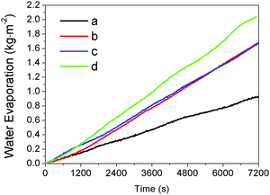 | ||
| Fig. 7 The water evaporation rate of four water samples under the same irradiation condition: (a) pure water, (b) water with a uniform dispersion of the hydrophilic Fe3O4@C particles, (c) water covered by a film made by random deposition of the hydrophobic Fe3O4@C particles (Fig. 5a), and (d) water covered by a uniform film of self-assembled hydrophobic Fe3O4@C particles (Fig. 5c). | ||
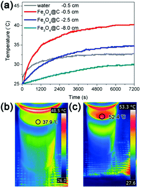
We also made direct measurements of the temperature distribution from the water surface to the bottom of the solution during the water evaporation process. Fig. 8a displays the temperature distributions during water evaporation of a solution covered by a self-assembled thin film of Fe3O4@C nanostructures. Under solar irradiation with intensity of 1 kW m−2, the temperature is higher at positions closer to the surface after a defined irradiation time. For example, upon irradiation for 2 h, the temperatures at 0.5 cm, 2.5 cm, and 8.0 cm (bottom) below the surface of the water were 40.2 °C, 34.8 °C, and 30.1 °C respectively, which confirmed more efficient heating at the interface than the bulk. Irradiating a pure water solution under the same condition led to a temperature of 32.8 °C at 0.5 cm from the surface, again confirming the effectiveness of interfacial heating. Furthermore, the temperature distributions from the water surface to bottom during the water evaporation process with and without Fe3O4@C film were also monitored by a thermal infrared imager, with the results shown in Fig. S2 (ESI†). The surface temperature of the Fe3O4@C floating film was 52.4 °C at the irradiation time of 2 h, which is 14.5 °C higher than the case of pure water (as shown in Fig. 8b and c). The temperature differences (ΔT) between the heated surface and a position of 0.5 cm below the surface was also calculated, showing a value of 4.1 °C for water self-evaporation and 12.2 °C in the case of interfacial solar heating with the assistance of the assembled Fe3O4@C film.
The effects of the carbon coating thicknesses and Fe3O4@C dosages on the water evaporation efficiencies are shown in Fig. 9a and b respectively. The water evaporation efficiency (k) of the Fe3O4 nanospheres was only 0.82 kg m−2 h−1. After coating with a thin carbon layer of 4 nm, the water evaporation efficiency (k) increased to 1.03 kg m−2 h−1, which is 1.26 times higher than that of the Fe3O4 nanospheres. However, further increasing the thickness of the carbon layer could hardly increase the k value (Fig. 9a), which was consistent with the results that the solar absorption of Fe3O4@C nanostructures with different carbon layer thickness were all around 90% (see Fig. 3). As shown in Fig. 9b and Table S2 (ESI†), the water evaporation efficiency increased initially with the increasing amount of Fe3O4@C nanostructures, but decreased when the dosage is beyond 0.083 kg m−2, most likely due to the light scattering and screening effect.39,40
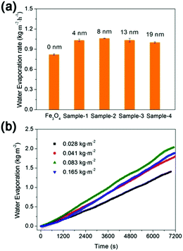 | ||
| Fig. 9 The effects of (a) the carbon coating thickness and (b) Fe3O4@C dosage on the water evaporation efficiency. | ||
To evaluate the quality of the condensed fresh water produced from this new solar evaporation process, we studied two real seawater samples obtained from the East China Sea and the South China Sea (the locations of the samples were marked in Fig. S3a, ESI†). A condensation chamber (see Fig. S3b and c, ESI†) was used for collecting the condensed fresh water. The typical water-quality indexes of the two seawater before and after desalination are present in Table S3 (ESI†). The conductivity (salinity) of the two condensed fresh water samples significantly reduced from 49![[thin space (1/6-em)]](https://www.rsc.org/images/entities/char_2009.gif) 800, 35
800, 35![[thin space (1/6-em)]](https://www.rsc.org/images/entities/char_2009.gif) 800 μS cm−1 to 15.3, 16.7 μS cm−1, respectively. The concentrations of other cations (Na+, K+, Ca2+, Mg2+, Fe3+) and anions (F−, Cl−, Br−, NO3−, SO42−) originally present in the seawater were also significantly decreased to (0.01–1.91) mg L−1, which were below the values defined by the Standards for drinking water quality in China,41 the US Environmental Protection Agency (EPA) standards,42 and the World Health Organization (WHO).43
800 μS cm−1 to 15.3, 16.7 μS cm−1, respectively. The concentrations of other cations (Na+, K+, Ca2+, Mg2+, Fe3+) and anions (F−, Cl−, Br−, NO3−, SO42−) originally present in the seawater were also significantly decreased to (0.01–1.91) mg L−1, which were below the values defined by the Standards for drinking water quality in China,41 the US Environmental Protection Agency (EPA) standards,42 and the World Health Organization (WHO).43
Recycling
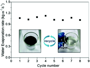
Recyclability is very important for solar-thermal conversion materials because it allows their reuse for cost reduction and also reduces the potential contamination to the environment. Our Fe3O4@C core–shell nanostructures have advantages over other solar-thermal conversion materials as they can be conveniently recycled by applying external magnetic fields. As shown in Video 1 (ESI†), we demonstrated that a Fe3O4@C floating film of 18.2 cm2 can be separated from water within 20 seconds by exposing to a 3 cm × 2 cm × 1 cm cuboid NdFeB magnet. The collected particles can reassemble into a new floating film within one second. The durability of the Fe3O4@C film was also investigated. As shown in Fig. 10, no water evaporation efficiency was lost even after eight cycles of solar evaporation. Moreover, the water contact angle of the Fe3O4@C nanostructures was still about 139° ± 0.2° (Fig. S4, ESI†) after eight cycles of use, which further confirmed the high chemical stability of the as-prepared Fe3O4@C nanostructures. As indicated in our previous study, PFOTS is a stable chemical and it cannot be decomposed under continuous irradiation of a simulated sunlight with light intensity of 1 kW m−2 four days.7Conclusions
In summary, we have demonstrated the synthesis of hydrophobic Fe3O4@C core–shell nanostructures and their self-assembly at the water surface into a well-defined thin film that can be used for efficient interfacial solar heating toward steam generation. The self-assembly process is driven by the combined action of thermal motion and surface tension of water. The formation of a thin film benefits the efficient use of the Fe3O4@C nanostructures for light absorption and heat transfer since the entire water surface can be covered by this thin film with a close contact. With the high solar absorption, fast film separation and reformation, enhanced water evaporation efficiency, high condensed water quality, and excellent durability, these Fe3O4@C core–shell nanostructures and the interfacial assembly strategy are expected to have potential uses in practical settings of solar desalination.Conflicts of interest
There are no conflicts to declare.Acknowledgements
This work was financially supported by the Public Welfare Technology Application Research Project of Zhejiang Province (No. LGG18E080002) and the National Natural Science Foundation of China (No. 51761145022). Acknowledgment is also made to the Donors of the American Chemical Society Petroleum Research Fund for partial support of this research (#55904-ND10).Notes and references
- M. A. Shannon, P. W. Bohn, M. Elimelech, J. G. Georgiadis, B. J. Marinas and A. M. Mayes, Nature, 2008, 452, 301–310 CrossRef CAS PubMed.
- H. R. Golsefatan, M. Fazeli, A. R. Mehrabadi and H. Ghomi, Desalination, 2017, 409, 183–188 CrossRef CAS.
- A. M. Alklaibi and N. Lior, Desalination, 2005, 171, 111–131 CrossRef CAS.
- P. Wang and T.-S. Chung, Water Res., 2012, 46, 4037–4052 CrossRef CAS PubMed.
- D. H. Kim, Desalination, 2011, 270, 1–8 CrossRef CAS.
- L. Zhang, B. Tang, J. Wu, R. Li and P. Wang, Adv. Mater., 2015, 27, 4889–4894 CrossRef CAS PubMed.
- M. Ye, J. Jia, Z. Wu, C. Qian, R. Chen, P. G. O'Brien, W. Sun, Y. Dong and G. A. Ozin, Adv. Energy Mater., 2017, 7, 1601811 CrossRef.
- Y. Ito, Y. Tanabe, J. Han, T. Fujita, K. Tanigaki and M. Chen, Adv. Mater., 2015, 27, 4302–4307 CrossRef CAS PubMed.
- Z. Liu, H. Song, D. Ji, C. Li, A. Cheney, Y. Liu, N. Zhang, X. Zeng, B. Chen, J. Gao, Y. Li, X. Liu, D. Aga, S. Jiang, Z. Yu and Q. Gan, Global Challenges, 2017, 1, 1600003 CrossRef PubMed.
- Y. Liu, J. Chen, D. Guo, M. Cao and L. Jiang, ACS Appl. Mater. Interfaces, 2015, 7, 13645–13652 CAS.
- X. Li, W. Xu, M. Tang, L. Zhou, B. Zhu, S. Zhu and J. Zhu, Proc. Natl. Acad. Sci. U. S. A., 2016, 113, 13953–13958 CrossRef CAS PubMed.
- J. Lou, Y. Liu, Z. Wang, D. Zhao, C. Song, J. Wu, N. Dasgupta, W. Zhang, D. Zhang, P. Tao, W. Shang and T. Deng, ACS Appl. Mater. Interfaces, 2016, 8, 14628–14636 CAS.
- X. Wang, G. Ou, N. Wang and H. Wu, ACS Appl. Mater. Interfaces, 2016, 8, 9194–9199 CAS.
- L. Shi, Y. Wang, L. Zhang and P. Wang, J. Mater. Chem. A, 2017, 5, 16212–16219 CAS.
- S. P. Surwade, S. N. Smirnov, I. V. Vlassiouk, R. R. Unocic, G. M. Veith, S. Dai and S. M. Mahurin, Nat. Nanotechnol., 2015, 10, 459–464 CrossRef CAS PubMed.
- K. K. Liu, Q. Jiang, S. Tadepalli, R. Raliya, P. Biswas, R. R. Naik and S. Singamaneni, ACS Appl. Mater. Interfaces, 2017, 9, 7675–7681 CAS.
- J. Zhou, Z. Sun, M. Chen, J. Wang, W. Qiao, D. Long and L. Ling, Adv. Funct. Mater., 2016, 26, 5368–5375 CrossRef CAS.
- Y. Zeng, K. Wang, J. Yao and H. Wang, Chem. Eng. Sci., 2014, 116, 704–709 CrossRef CAS.
- Y. Wang, G. Sun, J. Dai, G. Chen, J. Morgenstern, Y. Wang, S. Kang, M. Zhu, S. Das, L. Cui and L. Hu, Adv. Mater., 2017, 29, 1604257 CrossRef PubMed.
- Y. Wang, L. Zhang and P. Wang, ACS Sustainable Chem. Eng., 2016, 4, 1223–1230 CrossRef CAS.
- H. Ghasemi, G. Ni, A. M. Marconnet, J. Loomis, S. Yerci, N. Miljkovic and G. Chen, Nat. Commun., 2014, 5, 4449 CAS.
- G. Xue, K. Liu, Q. Chen, P. Yang, J. Li, T. Ding, J. Duan, B. Qi and J. Zhou, ACS Appl. Mater. Interfaces, 2017, 9, 15052–15057 CAS.
- Y. Zeng, J. Yao, B. A. Horri, K. Wang, Y. Wu, D. Li and H. Wang, Energy Environ. Sci., 2011, 4, 4074–4078 CAS.
- Y. Liu, S. Yu, R. Feng, A. Bernard, Y. Liu, Y. Zhang, H. Duan, W. Shang, P. Tao, C. Song and T. Deng, Adv. Mater., 2015, 27, 2768–2774 CrossRef CAS PubMed.
- Z. Wang, Y. Liu, P. Tao, Q. Shen, N. Yi, F. Zhang, Q. Liu, C. Song, D. Zhang, W. Shang and T. Deng, Small, 2014, 10, 3234–3239 CrossRef CAS PubMed.
- A. Politano, P. Argurio, G. Di Profio, V. Sanna, A. Cupolillo, S. Chakraborty, H. A. Arafat and E. Curcio, Adv. Mater., 2017, 29, 1603504 CrossRef PubMed.
- C. Liu, J. Huang, C.-E. Hsiung, Y. Tian, J. Wang, Y. Han and A. Fratalocchi, Adv. Sustainable Syst., 2017, 1, 1600013 CrossRef.
- H. Hu, Z. Wang, Q. Ye, J. He, X. Nie, G. He, C. Song, W. Shang, J. Wu, P. Tao and T. Deng, ACS Appl. Mater. Interfaces, 2016, 8, 20483–20490 CAS.
- L. Zhou, Y. Tan, J. Wang, W. Xu, Y. Yuan, W. Cai, S. Zhu and J. Zhu, Nat. Photonics, 2016, 10, 393–398 CrossRef CAS.
- Y. Liu, J. Lou, M. Ni, C. Song, J. Wu, N. P. Dasgupta, P. Tao, W. Shang and T. Deng, ACS Appl. Mater. Interfaces, 2016, 8, 772–779 CAS.
- S. Yu, Y. Zhang, H. Duan, Y. Liu, X. Quan, P. Tao, W. Shang, J. Wu, C. Song and T. Deng, Sci. Rep., 2015, 5, 13600 CrossRef PubMed.
- C. Chang, C. Yang, Y. Liu, P. Tao, C. Song, W. Shang, J. Wu and T. Deng, ACS Appl. Mater. Interfaces, 2016, 8, 23412–23418 CAS.
- G. Zhu, G. Xu, W. Zhao and F. Huang, ACS Appl. Mater. Interfaces, 2016, 8, 31716–31721 CAS.
- J. Wang, Y. Li, L. Deng, N. Wei, Y. Weng, S. Dong, D. Qi, J. Qiu, X. Chen and T. Wu, Adv. Mater., 2017, 29, 1603730 CrossRef PubMed.
- R. Chen, Z. J. Wu, T. Zhang, T. Yu and M. Ye, RSC Adv., 2017, 7, 19849–19855 RSC.
- H. Deng, X. L. Li, Q. Peng, X. Wang, J. P. Chen and Y. D. Li, Angew. Chem., Int. Ed., 2005, 44, 2782–2785 CrossRef CAS PubMed.
- Z. M. Chen, W. H. Xu, L. Jin, J. J. Zha, T. X. Tao, Y. Lin and Z. L. Wang, J. Mater. Chem. A, 2014, 2, 18339–18344 CAS.
- T. Lin, C. Yang, Z. Wang, H. Yin, X. Lu, F. Huang, J. Lin, X. Xie and M. Jiang, Energy Environ. Sci., 2014, 7, 967–972 CAS.
- M. Ye, Z. Chen, W. Wang, J. Shen and J. Ma, J. Hazard. Mater., 2010, 184, 612–619 CrossRef CAS PubMed.
- M. Muthukumar, J. Chem. Phys., 1997, 107, 2619–2635 CrossRef CAS.
- The Chinese National Standards for Drinking Water Quality (GB 5749-2006), 2006; http://www.nhfpc.gov.cn/cmsresources/zwgkzt/wsbz/new/20070628143525.pdf.
- 2012 Edition of the Drinking Water Standards and Health Advisories, Office of Water, US Environmental Protection Agency, http://https://www.epa.gov/ground-water-and-drinking-water/table-regulated-drinking-water-contaminants.
- WHO, Guidelines for Drinking-water Quality, World Health Organization, Geneva, 4th edn, 2011, http://apps.who.int/iris/bitstream/10665/44584/1/9789241548151_eng.pdf Search PubMed.
Footnote |
| † Electronic supplementary information (ESI) available: SEM image of the Fe3O4@C floating film; IR thermal images of water and water with the Fe3O4@C floating film on surface; water contact angle of Fe3O4@C nanostructures after 8 cycles; the proportion of light absorption in different spectrum regions; the zero-order kinetic equations and evaporation efficiencies of different water evaporation processes; the typical water-quality indexes of two natural water before and after water evaporation. See DOI: 10.1039/c7qm00374a |
| This journal is © the Partner Organisations 2017 |

