 Open Access Article
Creative Commons Attribution 3.0 Unported Licence
Gel electrolytes based on poly(vinylidenefluoride-co-hexafluoropropylene)/thermoplastic polyurethane/poly(methyl methacrylate) with in situ SiO2 for polymer lithium batteries
Zeyue He,
Qi Cao*,
Bo Jing,
Xianyou Wang and
Yuanyuan Deng
Key Laboratory of Environmentally Friendly Chemistry and Applications of Ministry of Education, College of Chemistry, Xiangtan University, Xiangtan 411105, China. Fax: +86 731 58298090; Tel: +86 731 58298090
First published on 13th January 2017
Abstract
Gel polymer electrolyte films based on poly(vinylidenefluoride-co-hexafluoropropylene) (PVDF–HFP), thermoplastic polyurethane (TPU) and poly(methyl methacrylate) (PMMA) with and without in situ SiO2 fillers are prepared by electrospinning a polymer solution at room temperature. The electrospun PVDF–HFP/TPU/PMMA blending membrane with 2% in situ SiO2 shows a highest ionic conductivity of 8.5 × 10⁻³ S cm−1 with electrochemical stability up to 5.9 V versus Li+/Li at room temperature. In addition, it shows a first charge of 168.5 mA h g−1, which is about 99% of the theoretical capacity of LiFePO4; the tensile strength of the PVDF–HFP/TPU/PMMA membrane is 10.8 MPa with elongation-at-break at 86.4%. With the outstanding electrochemical and mechanical performance, it is very suitable for application in polymer lithium batteries.
1. Introduction
Polymer lithium batteries are widely used in mass-produced digital devices and are gaining popularity in the electric vehicle market and energy storage systems because of their high energy density and long cycle life.1–5 In recent years, polymer-based nanocomposites which are used in polymer lithium batteries have attracted considerable academic and industrial attention,6–10 because polymer lithium batteries are safer than liquid lithium-ion batteries. Be that as it may, there is a long way to go in polymer lithium-ion battery large-scale application. A lot of techniques have been attempted to produce gel polymer electrolytes with excellent ionic transport properties and low crystallization, such as the phase inversion method, g-ray irradiation method, solvent casting technique, thermally induced phase separation (TIPS) technique, and electrospinning technique.11Among these methods, by using electrospinning technique can be easily prepare porous polymer framework materials. Furthermore the choice of matrices for gel polymer electrolyte (GPE) is also very important. And a lot of work has been done.12–20 Many investigations were devoted to copolymerize PVDF and its copolymers with other polymer for processing GPEs. Some article on based of coaggregant like PVDF/thermoplastic polyurethane (TPU) (PVDF/TPU), P(VDF-TrFE)/linear poly(ethylene oxide) (PEO) (P(VDF-TrFE)/PEO) and polyurethane/poly(vinylidene fluoride) (PU–PVDF) as GPEs for rechargeable lithium batteries have been reported lately.21,22 Poly(vinylidene fluoride-co-hexafluoropropylene) (PVDF–HFP) has been as the matrix of polymer electrolytes in lithium ion batteries. Making a comparison copolymers between PVDF and PVDF–HFP, the latter in the gel owns lower glass transition temperature, greater solubility for organic solvents and less crystallinity.23,24 Accordingly, there are more amorphous domains in PVDF–HFP which could absorb greater amounts of liquid electrolytes, and enough mechanical integrity profiting from the crystalline regions is conducive to prepare free-standing membrane as well. Thermoplastic polyurethane (TPU) contains two-phase microstructure which are soft segments and hard segments.25,26 The unfavorable interactions between the hard and soft segments make the system a microphase-separated one, which imparts elastomeric properties to polyurethane. The rubbery soft segments can dissolve alkali metal without formation of ionic cluster. On the other hand, the hard segment domains, which are in glassy state and are either distributed or interconnected throughout the rubbery phase, act as reinforcing filler and hence contribute to the dimensional stability of the GPEs. Because of this unique two-phase microstructure, the segmented polyurethanes find themselves very much useful as matrix materials for GPEs. Poly(methyl methacrylate) (PMMA) polymer matrixes have attracted much attention due to the advantages of excellent mechanical, chemical stability and considerable wettability.27–31 Besides, the functional group (–CO) of PMMA could interact with lithium ions and liquid electrolytes such as ethylene carbonate (EC), dimethylformamide (DMF). Therefore, PVDF–HFP, TPU and PMMA are combined with electrolyte solution to create GPEs,32,33 which had excellent performance in the lithium ion battery. Moreover doping ceramic fillers, such as TiO2, SnO2, MgO, Al2O3, and SiO2, is an effective way to improve the electrochemical and mechanical properties of GPE.
In this study, we choose poly(vinylidenefluoride-hexafluoro propylene) (PVDF–HFP)/thermoplastic polyurethane (TPU)/poly(methyl methacrylate) (PMMA) as electrospun matrix, PVDF–HFP/TPU/PMMA based gel polymer electrolyte with and without in situ SiO2 fillers are prepared by electrospinning technique. The properties of electrospun membranes prepared with in situ SiO2 fillers are observed to be comparatively better than the one prepared without in situ SiO2 fillers. And the electrospun PVDF–HFP/TPU/PMMA blending membrane with 2% in situ SiO2 has the most superior performance.
2. Experimental
2.1 Materials
Poly(vinylidene difluoride-co-hexafluoropropylene) (PVDF–HFP, Knyar Flex, LBG), thermoplastic polyurethane (TPU, Yantai Wanhua, 1190A) and poly(methyl methacrylate) (PMMA, Shanghai Chemical Reagents Co., China) were dried under vacuum at 80 °C for 24 h. LiClO4·3H2O (AR, Sinopharm Chemical Reagent Co., Ltd.) was dehydrated in vacuum oven at 120 °C for 72 h. 1 M liquid electrolyte was made by dissolving a certain quality of LiClO4 in ethylene carbonate (EC, Shenzhen CAPCHEM Technology Co., Ltd.)/propylene carbonate (PC, Shenzhen CAPCHEM Technology Co. Ltd.) (1/1, v/v). N,N-Dimethylformamide (DMF) and acetone were of analytical grade and used as received without further treatment.2.2 Preparation of PVDF–HFP/TPU/PMMA fibrous membrane
Four types of PVDF–HFP/TPU/PMMA fibrous membranes (a) without in situ SiO2 fillers, (b) with 1% in situ SiO2, (c) with 2% in situ SiO2 and (d) with 3% in situ SiO2 were prepared by electrospinning the following solutions, respectively.(a) A 11% solution of PVDF–HFP/TPU/PMMA (1![[thin space (1/6-em)]](https://www.rsc.org/images/entities/char_2009.gif) :
:![[thin space (1/6-em)]](https://www.rsc.org/images/entities/char_2009.gif) 1
1![[thin space (1/6-em)]](https://www.rsc.org/images/entities/char_2009.gif) :
:![[thin space (1/6-em)]](https://www.rsc.org/images/entities/char_2009.gif) 1, w/w/w) in DMF/acetone (3
1, w/w/w) in DMF/acetone (3![[thin space (1/6-em)]](https://www.rsc.org/images/entities/char_2009.gif) :
:![[thin space (1/6-em)]](https://www.rsc.org/images/entities/char_2009.gif) 1, w/w) was prepared by magnetic stirring for 12 h at room temperature.
1, w/w) was prepared by magnetic stirring for 12 h at room temperature.
(b) A 11% solution of PVDF–HFP/TPU/PMMA (1![[thin space (1/6-em)]](https://www.rsc.org/images/entities/char_2009.gif) :
:![[thin space (1/6-em)]](https://www.rsc.org/images/entities/char_2009.gif) 1
1![[thin space (1/6-em)]](https://www.rsc.org/images/entities/char_2009.gif) :
:![[thin space (1/6-em)]](https://www.rsc.org/images/entities/char_2009.gif) 1, w/w/w) in DMF/acetone (3
1, w/w/w) in DMF/acetone (3![[thin space (1/6-em)]](https://www.rsc.org/images/entities/char_2009.gif) :
:![[thin space (1/6-em)]](https://www.rsc.org/images/entities/char_2009.gif) 1, w/w) was prepared by magnetic stirring for 12 h at room temperature. For generating in situ SiO2, a small quantity of ammonium hydroxide (3–4 drops) was added to the polymer solution, which was followed by drop wise addition of the required quantity of TEOS under vigorous stirring. The stirring was continued at room temperature until forming a homogeneous solution.
1, w/w) was prepared by magnetic stirring for 12 h at room temperature. For generating in situ SiO2, a small quantity of ammonium hydroxide (3–4 drops) was added to the polymer solution, which was followed by drop wise addition of the required quantity of TEOS under vigorous stirring. The stirring was continued at room temperature until forming a homogeneous solution.
The hydrolysis and condensation reactions of TEOS can be represented by the following equations:
| Si(OC2H5)4 + 4H2O → Si(OH)4 + 4C2H5OH (hydrolysis) |
| Si(OH)4 → SiO2(s) + 2H2O (condensation) |
Both (c) and (d) are the same with (b), their difference is only in situ SiO2 content.
All of the solutions were electrospun under high voltage of 24.5 kV at room temperature, respectively. Nonwoven films were obtained on the collector plate and put on the table overnight to ensure the hydrolysis and condensation reactions fully completed. Then the electrospun nonwoven films were dried under vacuum at 80 °C for 12 h.
2.3 Preparation of gel polymer electrolytes
The thickness of the PVDF–HFP/TPU/PMMA films used were about 150 μm. At room temperature, the dried PVDF–HFP/TPU/PMMA films were activated by 1 M LiClO4–EC/PC liquid electrolyte solutions for 1 h in a glove box filled with argon. Wipe the surface of swelled membranes by filter paper and then the gel polymer electrolyte (GPE) was prepared.2.4 Membrane characterization
Scanning electron microscope (SEM, Hitachi S-3500 N, Japan) was used to examine the morphology of films. The thermal stability of the films was monitored using thermogravimetric analysis (model TQAQ 50, TA Company, USA). Fourier transform infrared (FT-IR) spectra of the samples were recorded using FT-IR Tensor 37 (Bruker, German) in the range of 400–4000 cm−1. Differential scanning calorimetry (DSC) characterization was performed using Perkin Elmer DSC7 instrument (USA) under a nitrogen atmosphere from 20 to 200 °C at a scan rate of 10 °C min−1. Samples were run under a nitrogen atmosphere over a temperature range of −90 to 230 °C. The crystallinity (χc) was calculated based on eqn (1) from the DSC curves
 | (1) |
 represent the fusion enthalpy of blend membrane and PVDF–HFP with 100% crystallinity, respectively. The value of
  is 104.7 J g−1. ϕ is the measuring weight fraction of PVDF–HFP.
The mechanical strength of the polymer gel films was measured by universal testing machines (UTM, Instron Instruments). The extension rate was kept at ∼5 mm min−1. The dimensions of the sheet used were 2 cm × 5 cm × 100 μm (width × length × thickness).
The electrolyte uptake was determined by measuring the weight increase and calculated according to eqn (2):
 | (2) |
The ionic conductivity of the composite film was measured with SS/PE/SS (SS means stainless steel plates) blocking cell by AC impedance measurement using Zahner Zennium electrochemical analyzer with a frequency range of 0.1–1 MHz. The thin films were prepared about 100 μm in thickness and 1.65 cm2 in area for impedance measurement. Thus, the ionic conductivity could be calculated from the following equation:
 | (3) |
2.5 Cell assembly and performance characteristics
Electrochemical stability was measured by a linear sweep voltammetry (LSV) of a Li/PE/SS (SS means stainless steel plates) cell using Zahner Zennium electrochemical analyzer at a sweep rate of 5 mV s−1, with voltage from 2 V to 7 V. For charge–discharge cycling tests, the Li/PE/LiFePO4 cell was assembled. The cell was subjected to electrochemical performance tests using an automatic charge–discharge unit, Neware battery testing system (model BTS-51, ShenZhen, CAPCHEM Technology China), between 2.0 and 4.5 V with different current densities at 25 °C.3. Results and discussion
3.1 Morphology and structure
Fig. 1 shows the SEM images of the membranes prepared by electrospinning of polymer solution with and without in situ SiO2 fillers. It can be seen that the electrospun nanofibers interlaced with each other randomly and formed a three-dimensional network structure. It is well known that TPU is a linear polymer material and the molecular structure is complicated. The duplicated carbamated-chain (–R–O–CO–NH–R–NH–CO–O–), which is in the hard segments of TPU, offers amino-group (–NH). The amino-group (–NH) can form hydrogen bonds with the strong electron-withdrawing functional group (–C–F) and (–CO). The functional group (–C–F) is in the backbone structure of PVDF–HFP, and the functional group (–CO) is in the backbone structure of PMMA. Therefore, PVDF–HFP, TPU and PMMA are miscible without any microphase separation as electrospun matrix. A network of interlaid and nearly straightened tubular structure fibers are found in the membrane without in situ ceramic fillers (Fig. 1(a)) and the surface of the membrane have no in situ silica films, moreover, there are a lot of the pore network structure. While the surface of the membrane with in situ silica films are found in the membrane with in situ gel polymer electrolyte films based on poly(vinylidenefluoride-co-hexafluoropropylene) (PVDF–HFP), thermoplastic polyurethane (TPU) and poly(methyl methacrylate) (PMMA) with and without in situ SiO2 fillers are prepared by electrospinning a polymer solution at room temperature. SiO2 (Fig. 1(b)–(d)), the differences of the three membranes are thickness and cover area of the in situ silica films. And as shown in Fig. 1(a)–(c), the nanofibers are very homogeneous and tenuous, however, the nanofibers of the membrane with 3% in situ SiO2 are unevenly distributed (Fig. 1(d)), this maybe added amount too much in situ SiO2 into the solution.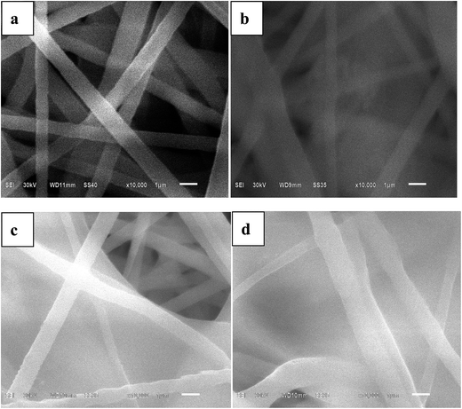 | ||
| Fig. 1 SEM images of electrospun PVDF–HFP/TPU/PMMA membranes (a) without in situ SiO2 (b) with 1% in situ SiO2 (c) with 2% in situ SiO2 (d) with 3% in situ SiO2. | ||
From the preparation steps of fibrous membrane, we can found that the hydrolysis and condensation reactions took place for generating in situ SiO2 fillers. The hydrolyzed precursor molecules Si(OC2H5)4 moved slowly because of the viscous polymer solution and the steric hindrance. So the probability of the resulting sol nuclei Si(OH)4 meeting together and growing into extended structure or large SiO2 particles is greatly reduced. As we know in situ SiO2 is conducive to the absorption of the electrolyte. Predicting the membrane with in situ SiO2 will have a higher electrolyte uptake.
3.2 FT-IR spectra analysis
FT-IR spectra of (a) TPU, (b) PVDF–HFP, (c) PMMA and (d) the composite membrane of PVDF–HFP/TPU/PMMA with in situ SiO2 are shown in Fig. 2. The characteristic absorption peaks of TPU are clearly identified, i.e. 2939 cm−1 (stretching band of –NH in hard phase) and 1700 cm−1 (stretching band of C![[double bond, length as m-dash]](https://www.rsc.org/images/entities/char_e001.gif) O). The typical peaks of PVDF–HFP are 1399 cm−1 (deformation vibration band of –CH2–), 1073 cm−1 (stretching band of C–C in the β-phase) and 873 cm−1 (band for amorphous phase). The vibrational peaks of PMMA are 1392 cm−1 (C–CH3 stretching), 1115 cm−1 (C–C–O bending vibrations). As we can see, the characteristic absorption peaks are shifted to (2922 and 1699 cm−1), (1399 and 1073 cm−1) and (1120 cm−1) in the complexes, respectively. And the strong electron-withdrawing functional group (–C–F) which is in the backbone structure of PVDF–HFP and functional group (–C–C–O) which is in the backbone structure of PMMA can form hydrogen bonds with amino-group (–NH) which is in the hard segments of TPU during to a shift of absorption bands (2922 cm−1, 1699 cm−1 and 1120 cm−1) in the characteristic absorption peaks of the PVDF–HFP/TPU/PMMA based membrane.
O). The typical peaks of PVDF–HFP are 1399 cm−1 (deformation vibration band of –CH2–), 1073 cm−1 (stretching band of C–C in the β-phase) and 873 cm−1 (band for amorphous phase). The vibrational peaks of PMMA are 1392 cm−1 (C–CH3 stretching), 1115 cm−1 (C–C–O bending vibrations). As we can see, the characteristic absorption peaks are shifted to (2922 and 1699 cm−1), (1399 and 1073 cm−1) and (1120 cm−1) in the complexes, respectively. And the strong electron-withdrawing functional group (–C–F) which is in the backbone structure of PVDF–HFP and functional group (–C–C–O) which is in the backbone structure of PMMA can form hydrogen bonds with amino-group (–NH) which is in the hard segments of TPU during to a shift of absorption bands (2922 cm−1, 1699 cm−1 and 1120 cm−1) in the characteristic absorption peaks of the PVDF–HFP/TPU/PMMA based membrane.
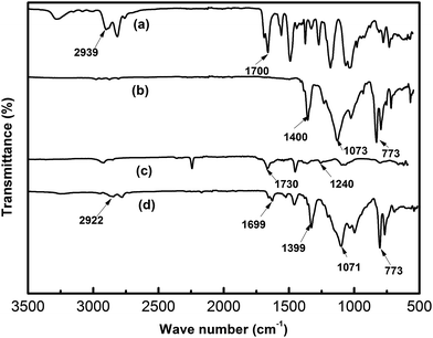 | ||
| Fig. 2 FTIR spectra of the electrospun membranes (a) TPU (b) PVDF–HFP (c) PMMA (d) PVDF–HFP/TPU/PMMA membranes with in situ SiO2. | ||
3.3 Thermal and DSC analysis
Fig. 3 presents the thermograms of membranes with and without in situ SiO2. The thermograms curve (a) of the membranes without in situ SiO2 illustrates three main weight loss processes: the initial weight loss occurring in the temperature range from 380 °C to 420 °C is also attributed to the PMMA; the weight loss in the phase two from 430 °C to 470 °C can be assigned to thermal decomposition reaction of TPU; the final perpendicular weight loss occurring in the temperature range from 480 °C to 510 °C is aroused from thermal collapse of PVDF–HFP. The thermograms curve (b) of the membranes with 2% in situ SiO2 also illustrates that there are three weight loss processes: the initial weight loss occurring in the temperature range from 400 °C to 500 °C is attributed to the removal of PMMA due to decomposition reaction of carbonyl, the loss occurring temperature is higher than the membranes without in situ SiO2, the weight loss in the second stage from 510 °C to 530 °C must be associated with the thermal decomposition reaction of TPU; the final perpendicular weight loss occurring in the temperature range from 530 °C to 580 °C is aroused from thermal collapse of PVDF–HFP. The higher the temperature of the weight loss, meaning that, its thermal stability is better. The results suggested that the membrane with in situ SiO2 have the excellent thermal stability.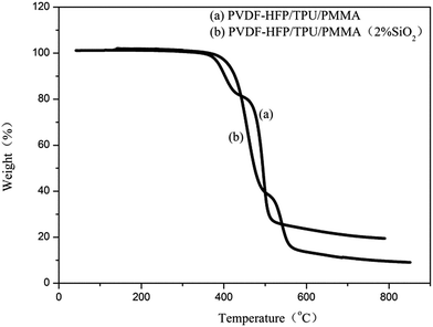 | ||
| Fig. 3 Thermograms of electrospun PVDF–HFP/TPU/PMMA membranes (a) without in situ SiO2 (b) with 2% in situ SiO2. | ||
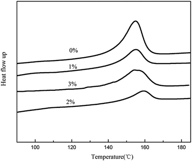
Fig. 4 displays DSC curves and the following observations were made. As shown in Fig. 4, firstly, the heating curve of eletrospun PVDF–HFP/TPU/PMMA membranes without in situ SiO2 membrane showed a melting peak at temperature of 155.8 °C, while the membrane with 2% in situ SiO2 has the highest melting temperature which is 160.3 °C. As shown in Table 1, the melting enthalpy (ΔHf) of the eletrospun membranes with in situ SiO2 is much lower than that of the membrane without in situ SiO2. According to eqn (1), the percentage of crystallinity values of the membrane is 21.30% (without in situ SiO2), 17.49% (with 1% in situ SiO2), 14.73% (with 2% in situ SiO2), 16.78% (with 3% in situ SiO2), respectively. Low crystallinity of membrane can supply a beneficial condition for conductivity enhancement. The results suggested that the membrane with 2% in situ SiO2 based gel polymer electrolyte may have the excellent ionic conductivity.
| Materials (SiO2) | ΔHf (J g−1) | Crystallinity χc (%) |
|---|---|---|
| 0% | 22.30 | 21.30 |
| 1% | 18.32 | 17.49 |
| 2% | 15.43 | 14.73 |
| 3% | 17.57 | 16.78 |
3.4 Electrolyte uptake and ionic conductivity
Fig. 5 shows the uptake behavior of the electrospun PVDF–HFP/TPU/PMMA fibrous membranes. The percentage of electrolyte uptake can be calculated according to eqn (2). The fibrous film without in situ SiO2 has liquid electrolyte uptake up to 236 wt% within 2 min, in the meantime, the membranes with 1% in situ SiO2 is 295%, the membrane with 2% in situ SiO2 is 330% and the membrane with 3% in situ SiO2 is 350%. In order to reach up to the maximum uptake, the electrospun fibrous membrane were immersed into liquid electrolyte 15 min, it is found that the uptake of the electrolyte solution reaches up to 337% (the membrane without in situ SiO2), 360% (the membrane with 1% in situ SiO2), 395% (the membrane with 2% in situ SiO2) and 415% (the membrane with 3% in situ SiO2), respectively. After 15 min, it is found that when the electrolyte uptake carves stabile, the membrane with in situ SiO2 (2% and 3%) show higher electrolyte uptake percentage.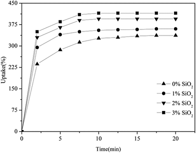 | ||
| Fig. 5 The uptake behavior of electrospun PVDF–HFP/TPU/PMMA membranes with and without in situ SiO2. | ||
The absorption of large quantities of liquid electrolyte by the composite membranes results from the high porosity of the membranes and the storage protection of in situ SiO2. From the SEM images of the membranes, we can find that the fully interconnected pore structure makes fast penetration of the liquid into the membrane possible, and hence the uptake process is stabile within the initial 15 min. Because in situ SiO2 form a layer of film on the surface of fibrous membranes, which is good to help the absorption of the electrolyte storage, so it has the higher electrolyte uptake percentage, which means more Li/Li+ exchanging in the same volume. This leads it to have a high ionic conductivity.
Fig. 6 shows the interfacial resistance of the gel polymer electrolytes with and without in situ SiO2. It can be observed clearly from Fig. 6(a) that the bulk resistance (Rb) of the gel polymer electrolytes with 2% in situ SiO2 is 0.71 Ω. And in Fig. 6(b) the electrolyte with 1% in situ SiO2 has a bulk resistance of 0.88 Ω. The electrolyte with 3% in situ SiO2 has a bulk resistance of 1.10 Ω in Fig. 6(c). However, in Fig. 6(d) the electrolyte without in situ SiO2 has a bulk resistance of 1.46 Ω. We could calculate ionic conductivity by eqn (3), the gel polymer electrolyte film has an ionic conductivity of 4.2 × 10⁻³ S cm−1 (GPE without in situ SiO2), 6.8 × 10⁻³ S cm−1 (GPE with 1% in situ SiO2), 8.5 × 10⁻³ S cm−1 (GPE with 2% in situ SiO2), 5.5 × 10⁻³ S cm−1 (GPE with 3% in situ SiO2), respectively.
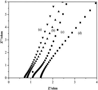 | ||
| Fig. 6 Impedance spectra of gel polymer electrolytes (a) with 2% in situ SiO2 (b) with 1% in situ SiO2 (c) with 3% in situ SiO2 (d) without in situ SiO2. | ||
From the morphology of the prepared porous electrospun membranes in Fig. 1, it can be seen that there are many interconnected pores in the porous membranes, which help polymer membrane absorbs large quantity of liquid electrolyte, then they form a gelled polymer electrolyte together. What's more, the pores are also interconnected by the sub-micron windows, which offer channels for the migration of ions and are small enough to well retain the electrolyte solution in the membrane. And the more uptake of liquid electrolyte, the more Li+ in the same volume. As in situ SiO2 is semi-conductor inorganic nano ions, itself exists body resistance, so a balanced amount of in situ SiO2 adding can increase absorption of liquid electrolyte and improve the ionic conductivity. So the GPE with 2% in situ SiO2 has the highest ionic conductivity.
3.5 Electrochemical stability
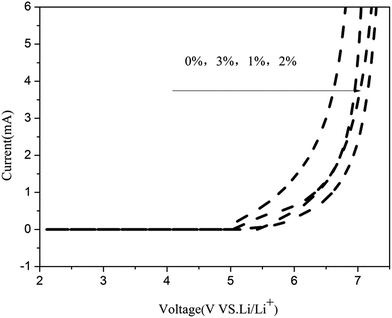
Fig. 7 shows the LSV curves of the gel polymer electrolytes. It is seen that the electrochemical stability of gel polymer electrolyte without in situ SiO2 is at 5.4 V. With the addition of the in situ SiO2 fillers, the stability of the gel polymer electrolytes are further enhanced. The gel polymer electrolyte delivers a electrochemical stability of 5.8 V (GPE with 1% in situ SiO2), 5.9 V (GPE with 1% in situ SiO2), 5.6 V (GPE with 3% in situ SiO2). As we can see that the PVDF–HFP/TPU/PMMA gel polymer electrolyte with 2% in situ SiO2 is shows the best electrochemical stability up to 5.9 V, which is much higher than the requirements of practical applications, rendering it suitable for most of the common cathode materials used in lithium ion batteries. Besides, a decomposition process, which is associated with electrode/electrolyte, results in the onset of current flow in the high voltage range. And this onset voltage is the upper limit of the electrolyte stability range. There is almost no electrochemical reaction in the potential range from 2 V to 5.9 V for PVDF–HFP/TPU/PMMA gel polymer electrolyte with 2% in situ SiO2. The beginning of current flow at 5.9 V represents the decomposition of the lithium electrode. A considerable current began to flow along with further increase of the cell voltage, indicating the onset of electrolyte decomposition process.Hence, the partial swelling of the in situ SiO2 membrane with a large surface area significantly contributed to the increase in the stability of the electrolyte solution under electrochemical environments, although the ionic conduction occurred mainly through the entrapped liquid electrolyte in the pore structure. The swollen phase of the membrane probably includes the complex compounds such as associated VDF–Li+ groups. This complex formation with lithium ion and VDF groups of PVDF–HFP enhances the electrochemical stability of GPEs. The electrochemical stability was also influenced by the high porosity, large and fully interconnected pores. So the gel polymer electrolyte with 2% in situ SiO2 shows the best electrochemical stability.
The high stability of these polymer electrolytes indicate that them are very suitable for applications in lithium-ion battery.
3.6 Mechanical property
Fig. 8 shows the stress–strain curves of the polymer membranes. The test results show that the mechanical properties of membranes are improved with in situ SiO2 fillers. The PVDF–HFP/PMMA membrane without in situ SiO2 extended only 62% with a poor breaking tensile strength 6.10 MPa. Referring to the PVDF–HFP/PMMA film with 2% in situ SiO2 fillers, the membrane has 86.4% elongation and was broken under the 10.8 MPa tensile strength. Both the tensile strength and elongation at break were enhanced. From the SEM images, we can see clearly that there is a in situ silica film on the surface of the polymer membrane. Thus it has a great contact area with the polymeric matrix. When the material is struck, the more microcracking will absorb more impact energy. So the further expansion of the cracks is blocked.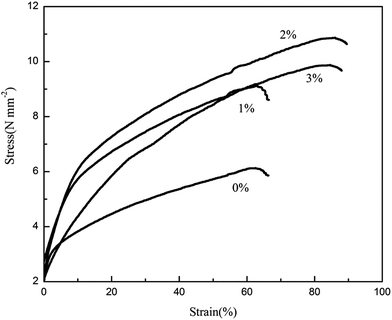 | ||
| Fig. 8 Stress–strain curves of electrospun PVDF–HFP/TPU/PMMA membranes with and without in situ SiO2. | ||
Elongation at break often reflects the impact performance of material and the impact resistance is shown by the material toughness. The higher toughness in mechanical properties will reduce the risk of the collapse of the membrane, which is suggests that the membrane with in situ SiO2 fillers is more suitable for application in polymer lithium ion batteries.
3.7 Evaluation in Li/LiFePO4 cell
As active materials LiFePO4 as cathode has high theoretical capacity 170 mA h g−1, the practical applicability of the electrospun fibrous membrane polymer electrolyte is tested in Li/CPE/LiFePO4 cell. Fig. 9 shows the first charge–discharge capacity curves of Li/GPE/LiFePO4. The gel polymer electrolyte film (GPE without in situ SiO2) delivers a charge capacity of 164.84 mA h g−1 and discharge capacity of 162.15 mA h g−1, while the gel polymer electrolyte film with in situ SiO2 delivers a charge capacity of 166.80 mA h g−1 (GPE with 1% in situ SiO2), 168.23 mA h g−1 (GPE with 2% in situ SiO2), 166.50 mA h g−1 (GPE with 3% in situ SiO2), and discharge capacity of 164.98 mA h g−1 (GPE with 1% in situ SiO2), 166.58 mA h g−1 (GPE with 2% in situ SiO2), 164.38 mA h g−1 (GPE with 3% in situ SiO2), respectively. We can found that the gel polymer electrolyte film with 2% in situ SiO2 own the best charge–discharge capacity, and it first charge–discharge efficiency up to 99% of the theoretical capacity, which means that the cycle efficiency is very high. On the one hand, this may be the result of the compatibility of PVDF–HFP, TPU and PMMA in polymer matrix. At the same time, the membranes with in situ SiO2 have a stable structure, a large number of pores for Li+ exchanging and high specific surface area in contacting with electrode also make outstanding electrochemical performance.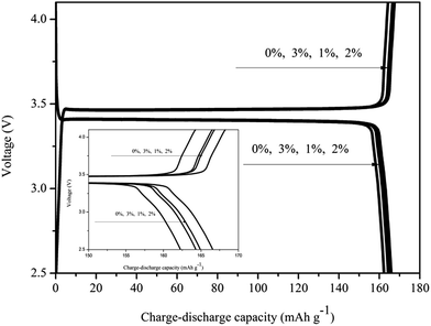 | ||
| Fig. 9 First charge–discharge capacities of GPEs based on electrospun membrane with and without in situ SiO2. | ||
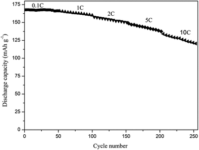
Upon that we studied the cycle performance of cell with 2% in situ SiO2 at different current rates from 0.1 to 10C illustrated in Fig. 10. At lower current rates (0.1C), the capacity retentions 99.5% after 50 cycles. Even at high-rate of 10C, the capacity retention is as high as 91% and the cell still remains a discharge capacity of 125.03 mA h g−1 after 50 cycles, which clearly demonstrates high capacity retention of the cells.
 | ||
| Fig. 10 The cycle performance of cell with 2% in situ SiO2 at different current rates (1C = 170 mA h g−1). | ||
The results of evaluation in Li/LiFePO4 cell indicate the electrochemical performance of composite gel polymer electrolytes with in situ SiO2 is further enhanced. The outstanding electrochemical performance of the cell with in situ SiO2 are attributed to a fairly high liquid electrolyte uptake of fibrous membrane, a high ionic conductivity and no microphase separation of mingling among PVDF–HFP, TPU and PMMA. Beyond that, good electrode/electrolyte interface contact and stable structure also have contribute to excellent cell performance.
4. Conclusions
PVDF–HFP/TPU/PMMA based gel polymer electrolytes with and without in situ SiO2 blend/composite membranes were prepared by electrospinning the 11 wt% polymer solution in DMF/acetone (3![[thin space (1/6-em)]](https://www.rsc.org/images/entities/char_2009.gif) :
:![[thin space (1/6-em)]](https://www.rsc.org/images/entities/char_2009.gif) 1, w/w) at room temperature. The gel polymer electrolytes were prepared by activating the dried electrospun nonwoven films in 1 M LiClO4–EC/PC liquid electrolyte solutions.
1, w/w) at room temperature. The gel polymer electrolytes were prepared by activating the dried electrospun nonwoven films in 1 M LiClO4–EC/PC liquid electrolyte solutions.
The gel polymer electrolyte with in situ 2% SiO2 has a high ionic conductivity of 8.5 × 10⁻³ S cm−1 with electrochemical stability up to 5.9 V versus Li+/Li at room temperature. And the first charge–discharge capacity of PVDF–HFP/TPU/PMMA based gel polymer electrolyte with in situ 2% SiO2 lithium battery is 168.5 mA h g−1, which is about 99% of the theoretical capacity of LiFePO4. The cell shows a very stable charge–discharge behavior and little capacity loss under current constant voltage condition after 50 cycles at the 0.1C-rate at 25 °C, and exhibiting a good compatibility with lithium electrodes. And it has a perfect mechanical stability with high tensile strength (10.8 MPa) and elongation at break (86.4%). Both tensile strength and elongation allow safe operation in rechargeable lithium ion polymer batteries. These results indicated that incorporation of in situ generated 2% SiO2 is more efficient in improving the properties of gel polymer electrolyte for practical application.
Acknowledgements
The workers gratefully appreciate the financial supports from the Youth Project of National Nature Science Foundation of China (Grant No. 51103124 and No. 51203131) and Hunan Province Universities Innovation Platform of Open Fund Project (11K067).References
- C. H. Tsao and P. L. Kuo, Poly(dimethylsiloxane) hybrid gel polymer electrolytes of a porous structure for lithium ion battery, J. Membr. Sci., 2015, 489, 36–42 CrossRef CAS.
- P. Raghavan, X. Zhao, C. Shin, D. H. Baek, J. W. Choi, J. M. Manuel, Y. Heo and J. H. Ahn, Preparation and electrochemical characterization of polymer electrolytes based on electrospun poly(vinylidene fluoride-co-hexafluoropropylene), J. Power Sources, 2010, 195, 6088–6094 CrossRef CAS.
- J. W. Fergus, Ceramic and polymeric solid electrolytes for lithium-ion batteries, J. Power Sources, 2010, 195, 4554–4569 CrossRef CAS.
- Z. Z. Zhang, G. Sui, H. T. Bi and X. P. Yang, Radiation-crosslinked nanofiber membranes with well-designed core–shell structure for high performance of gel polymer electrolytes, J. Membr. Sci., 2015, 492, 77–87 CrossRef CAS.
- B. Scrosati and J. Garche, Lithium batteries: status, prospects and future, J. Power Sources, 2010, 195, 2419–2430 CrossRef CAS.
- R. Prasanth, N. Shubha and H. H. Hng, Effect of poly(ethylene oxide) on ionic conductivity and electrochemical properties of poly(vinylidenefluoride) based polymer gel electrolytes prepared by electrospinning for lithium ion batteries, J. Power Sources, 2014, 245, 283–291 CrossRef CAS.
- P. Gajendran and R. Saraswathi, Electrocatalytic performance of poly(o-phenylenediamine)–Pt–Ru nanocomposite for methanol oxidation, J. Solid State Electrochem., 2013, 17, 2741–2747 CrossRef CAS.
- G. Colucci, C. Beltrame, M. Giorcelli, A. Veca and C. Badini, A novel approach to obtain conductive tracks on PP/MWCNT nanocomposites by laser printing, RSC Adv., 2016, 6, 28522–28531 RSC.
- W. L. Li, Y. H. Wu, J. W. Wang, D. Huang, L. Z. Chen and G. Yang, Hybrid gel polymer electrolyte fabricated by electrospinning technology for polymer lithium-ion battery, Eur. Polym. J., 2015, 67, 365–372 CrossRef CAS.
- O. Y. Posudievsky, O. A. Kozarenko, V. S. Dyadyun, V. G. Koshechko and V. D. Pokhodenko, Advanced electrochemical performance of hybrid nanocomposites based on LiFePO4 and lithium salt doped polyaniline, J. Solid State Electrochem., 2015, 19, 2733–2740 CrossRef CAS.
- A. M. Stephan, N. G. Renganathan and S. Gopukumar, Cycling behavior of poly(vinylidene fluoride-hexafluoro propylene)(PVDF–HFP) membranes prepared by phase inversion method, Mater. Chem. Phys., 2004, 85, 6–11 CrossRef CAS.
- Z. H. Li, H. P. Zhang, P. Zhang and Y. P. Wu, P(VDF-HFP)-based micro-porous composite polymer electrolyte prepared by in situ hydrolysis of titanium tetrabutoxide, J. Appl. Electrochem., 2008, 38, 109–114 CrossRef CAS.
- W. L. Li, Y. H. Wu, J. W. Wang, D. Huang, L. Z. Chen and G. Yang, Hybrid gel polymer electrolyte fabricated by electrospinning technology for polymer lithium-ion battery, Eur. Polym. J., 2015, 67, 365–372 CrossRef CAS.
- W. M. Kang, N. P. Deng, X. M. Ma, J. G. Ju, L. Li, X. H. Liu and B. W. Cheng, A thermostability gel polymer electrolyte with electrospun nanofiber separator of organic F-doped poly-m-phenyleneisophthalamide for lithium-ion battery, Electrochim. Acta, 2016, 216, 276–286 CrossRef CAS.
- D. H. Kang and H. W. Kang, Surface energy characteristics of zeolite embedded PVDF nanofiber films with electrospinning process, Appl. Surf. Sci., 2016, 387, 82–88 CrossRef CAS.
- P. G. Ramos, N. J. Morales, S. Goyanes, R. J. Candal and J. Rodriguez, Moisture-sensitive properties of multi-walled carbon nanotubes/polyvinyl alcohol nanofibers prepared by electrospinning electrostatically modified method, Mater. Lett., 2016, 185, 278–281 CrossRef CAS.
- Z. C. Yao, Y. Gao, M. W. Chang, Z. Ahmad and J. S. Li, Regulating poly-caprolactone fiber characteristics in situ during one-step coaxial electrospinning via enveloping liquids, Mater. Lett., 2016, 183, 202–206 CrossRef CAS.
- J. Nunes-Pereira, C. M. Costa and S. Lanceros-Méndez, Polymer composites and blends for battery separators: state of the art, challenges and future trends, J. Power Sources, 2015, 281, 378–398 CrossRef CAS.
- M. Mohammadi, P. Alizadeh and F. J. Clemens, Synthesis of CaCu3Ti4O12 nanofibers by electrospinning, Ceram. Int., 2015, 41, 13417–13424 CrossRef CAS.
- Q. Xiao, Z. H. Li, D. Gao, T. He and H. Zhang, Preparation and electrochemical performance of gel polymer electrolytes with a novel star network, J. Appl. Electrochem., 2009, 39, 247–251 CrossRef CAS.
- C. M. Costa, J. Nunes-Pereira and L. C. Rodrigues, et al., Novel poly(vinylidenefluoride-trifluoroethylene)/poly(ethylene oxide) blends for battery separators in lithium-ion applications, Electrochim. Acta, 2013, 88, 473–476 CrossRef CAS.
- C. M. Costa, M. M. Silva and S. Lanceros-Mendez, Battery separators based on vinylidene fluoride (VDF) polymers and copolymers for lithium ion battery applications, RSC Adv., 2013, 3(29), 11404–11417 RSC.
- S. Abbrent, J. Plestil, D. Hlavata, J. Lindgren, J. Tegenfeldt and A. Wendsjo, Crystallinity and morphology of PVDF–HFP-based gel electrolytes, Polymer, 2001, 42, 1407–1416 CrossRef CAS.
- N. Wu, Q. Cao, X. Y. Wang, X. Y. Li and H. Y. Deng, A novel high-performance gel polymer electrolyte membrane basing on electrospinning technique for lithium rechargeable batteries, J. Power Sources, 2011, 196, 8638–8643 CrossRef CAS.
- J. Van Heumen and J. Stevens, The role of lithium salts in the conductivity and phase morphology of a thermoplastic polyurethane, Macromolecules, 1995, 28, 4268–4277 CrossRef CAS.
- H.-H. Kuo, W.-C. Chen, T.-C. Wen and A. Gopalan, A novel composite gel polymer electrolyte for rechargeable lithium batteries, J. Power Sources, 2002, 110, 27–33 CrossRef CAS.
- H. Y. Liu, L. L. Liu, C. L. Yang, Z. H. Li, Q. Z. Xiao, G. T. Lei and Y. H. Ding, A hard-template process to prepare three-dimensionally macroporous polymer electrolyte for lithium-ion batteries, Electrochim. Acta, 2014, 121, 328–336 CrossRef CAS.
- Z. Zhong, Q. Cao, X. Y. Wang, N. Wu and Y. Wang, PVC–PMMA composite electrospun membranes as polymer electrolytes for polymer lithium-ion batteries, Ionics, 2012, 18, 47–53 CrossRef CAS.
- A. Zalewska, A. Bernakiewicz, M. Bystrzycka, M. Marczewski and N. Langwald, Properties of gel electrolytes based on PVDF/HFP containing anion receptors, Int. J. Hydrogen Energy, 2014, 39, 2977–2987 CrossRef CAS.
- D. Y. Song, C. Xu, Y. F. Chen, J. R. He, Y. Zhao, P. J. Li, W. Lin and F. Fu, Enhanced thermal and electrochemical properties of PVDF–HFP/PMMA polymer electrolyte by TiO2 nanoparticles, Solid State Ionics, 2015, 282, 31–36 CrossRef CAS.
- J. Cao, L. Wang, M. Fang, X. He, J. Li, J. Gao, L. Deng, J. Wang and H. Chen, Structure and electrochemical properties of composite polymer electrolyte based on poly vinylidene fluoride–hexafluoropropylene/titania–poly(methyl methacrylate) for lithium-ion batteries, J. Power Sources, 2014, 246, 499–504 CrossRef CAS.
- S. K. Tripathi, A. Gupta and M. Kumari, Studies on electrical conductivity and dielectric behaviour of PVdF–HFP–PMMA–NaI polymer blend electrolyte, Bull. Mater. Sci., 2012, 35, 969–975 CrossRef CAS.
- E. Quartarone and P. Mustarelli, Electrolytes for solid-state lithium rechargeable batteries: recent advances and perspectives, Chem. Soc. Rev., 2011, 40, 2525–2540 RSC.
| This journal is © The Royal Society of Chemistry 2017 |

