 Open Access Article
Massive, eco-friendly, and facile fabrication of multi-functional anodic aluminum oxides: application to nanoporous templates and sensing platforms†
Seok Hwan Jeong‡
 a,
Hea Lin Im‡
 a,
Seongin Hong
 a,
Heekyeong Park
 a,
Jongyeol Baek
 a,
Dong Hyuk Park
 *b,
Sunkook Kim*a and
Young Ki Hong
 *a
*a
aDepartment of Electronics and Radio Engineering, Kyung Hee University, Gyeonggi 446-701, Republic of Korea. E-mail: intel0616@gmail.com; imhyke0419@gmail.com
bDepartment of Applied Organic Materials Engineering, Inha University, Incheon 402-751, Republic of Korea. E-mail: donghyuk@inha.ac.kr
First published on 16th January 2017
Abstract
In this paper, we report on an efficient and eco-friendly approach to fabricate AAOs in oxalic acid electrolyte, which exhibits a relatively wide range of electrolyte temperatures for stable anodization. Our strategy consists of simultaneous multi-surfaces anodization (SMSA) for fabricating plural AAOs and direct detachment of those AAOs from an aluminum (Al) substrate by applying stair-like reverse biases (SRBs) in the same electrolyte used for the SMSAs. A unit sequence including SMSA sequentially combined with SRBs-based detachment can be applied repeatedly to the same Al substrate for mass production of AAOs. Dimensional characteristics of AAOs were quantitatively controlled with respect to the electrolyte temperature as well as the number of applied sequences, and SRBs-based direct detaching characteristics depending on the AAO thickness were investigated as a function of the number of stairs in SRBs. The AAOs fabricated here were used as nanoporous templates for synthesizing π-conjugated polymer nanomaterials with various diameters, and their structural and optical characteristics were studied with respect to their physical dimensions. We also fabricated capacitive humidity sensors designed on interdigitated electrode structures with nanoporous AAOs, and discussed their superior device performances.
1. Introduction
Anodization is a tradition-long technique, which has been utilized for a metal surface treatment enabling an anti-corrosive protection against atmospheric environments as well as an adhesive reinforcement of paint primers.1–4 After the report on the two-step anodization resulting in a distinct improvement of the structural periodicities over the extended spatial regime,5,6 anodic aluminum oxides (AAOs) have been widely adopted in diverse research fields, such as representative nanoporous templates for one-dimensional (1-dim.) nanostructures,7–13 membrane filters,14–17 evaporation/etching masks,18–21 humidity sensors,22–28 energy storage devices,29–32 and bio-applications,33–36 etc. These applications excluding surface treatments require AAOs with freestanding forms, i.e., separation from aluminum (Al) substrate, thus various strategies have been developed in the viewpoints of not only AAO fabricating (anodizing) but also AAO separating procedure.For AAO fabrication, mild anodization (MA) techniques were well-established under three major acidic (sulfuric, oxalic, and phosphoric) electrolytes.4,5,37–39 However, relatively lower intensities of the anodic voltages resulted in low yield of AAO fabrication due to the slow growth rates, which would get worse under the two-step anodizing conditions. In order to overcome these limitations of MAs, hard anodization (HA) techniques have been developed, in which AAOs were produced by using relatively higher anodic voltages in sulfuric/oxalic acid electrolytes or under more concentrated phosphoric acid electrolytes.40–49 AAOs fabricated in HA conditions exhibit clear enhancements of nanopores' periodicities as well as growth rates, however, the initial nanopore diameter (DP0) and interpore distance (Dint) of the AAOs through the HA are larger than those from the MA, which could restrict their potential applicability. In addition, high current densities originated from the HA conditions intensify the exothermic characteristics of anodization, so expensive cooling systems41 or additional cooling reagents in acidic electrolyte should be needed for compensating the heating and/or burning problems.50
A couple of alternative approaches have been proposed by considering the advantages and disadvantages of both MA and HA. Kashi et al. reported on an accelerated MA method, which exhibited about ten times faster AAO growth rate than conventional MA by selectively increasing temperature at backside of Al substrate.51 Cheng and Ngan demonstrated that anodization under higher acid concentration and temperature than standard MA conditions could improve growth rate of AAO and arrangement of the hexagonal unit cells.52 Xu and co-workers reported that there existed on the optimal amount of ethanol addition into the acidic electrolyte, which was typically used as a coolant for HA,46–49 for increasing AAO growth rate under MA condition.53
For separating an AAO from the Al substrate, toxic chemicals containing heavy metal ions, such as mercury chloride5,6,19,21,37,54–57 or copper chloride (CuCl2)42,48,58,59 are commonly used for dissolving the remaining part of the Al substrate, which is another time-consuming part in the conventional AAO fabricating methods. The chemical etching and AAO separation time could be reduced a little by adding hydrochloric acid into CuCl2 aqueous solution,10,30,43–45 however, these chemical etching-based AAO separation methods show critical disadvantages in terms of environmentally hazardous residues and dissipating valuable resources. Therefore, many efforts have been made for direct detachment of an AAO from the Al substrate, which can guarantee a reusability of the remaining Al substrate, by reversing polarity of the anodic voltage,14,60 or applying a pulse-type anodic voltage.29,58,59,61,62 The former strategy took too much time (e.g., 12–24 h),60 and details of the detaching mechanism were not fully understood. Recently, Choudhary and Szalai reported on thickness-dependent behavior of a cathodic delamination of an AAO in nitric acid electrolyte and accumulation of the texturing effects.63 The latter ones should require butanedione and/or perchloric acid-based detaching electrolytes, which are also hazardous and highly reactive, although the definite reduction of the AAO separating time and recent report on the proposed detaching mechanism.64 Furthermore, changing electrolyte between anodizing and detaching would require an additional cleaning procedure, which might induce a complicated process within whole procedure.
Yanagishita and Masuda upgraded their previous two-step anodization technique, which composed of normal (upper) and sacrificial (lower) AAO layers with different solubility.65 A sacrificial AAO, fabricated under much higher acid concentration (12 M), was dissolved more easily in appropriate etchants for separating normal AAO with through-hole structure, which was attributed that more anions would infiltrate into alumina (Al2O3) region due to the high acid concentration4,66 enhancing the solubility of the more contaminated sacrificial AAO. However, besides a possibility for pore-widening effect on the upper AAO during dissolution of the sacrificial layer, further investigation might be needed for an upper AAO fabricated under the HA conditions, which also contains abundant anions due to the high current densities.40,44
It should be noted that all the above-listed research results have been applied onto a “mono-surface” of the Al substrate, which significantly limit the yield of AAO fabrication. From these points of view, Hong and Joo et al. reported on a novel concept for high yield and environmental friendly fabrication of AAOs in a sulfuric acid electrolyte under the MA condition.67 This technique consists of simultaneous multi-surfaces anodization (SMSA) for producing plural AAOs at one time and direct detachment of those AAOs from an Al substrate by applying stair-like reverse biases (SRBs) in the same acidic electrolyte used for SMSA. One of the most fascinating advantages of this simple strategy is that plural as well as almost identical AAOs can be repeatedly fabricated from “multi-surfaces” on a same Al substrate as long as it remains without the toxic/reactive chemicals and sophisticated procedures.
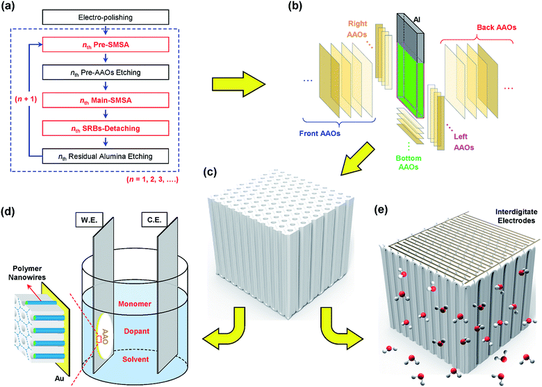
Considering the history and trend in the anodization-related research fields, it would be highly demanded to extend the SMSA and SRBs-based techniques in the other acidic electrolyte, which also guarantees the resultant AAOs with distinct mechanical as well as dimensional properties for various applications. In this regard, we chose oxalic acid, which has relatively wide range of the electrolyte temperatures for stable anodizations comparing with sulfuric acid, and lower anodic voltage than that of phosphoric acid. In this paper, we present a facile and eco-friendly strategy for mass-fabrication of the AAOs and their various applications, as shown in Fig. 1. SMSAs and SRBs-based detachment were successfully realized in an oxalic acid electrolyte under the MA condition. A unit sequence including two-step SMSAs sequentially combined with SRBs-based detachment was repeated up to six times on multi-surfaces of a same Al substrate. Dimensional characteristics of AAOs were quantitatively investigated as functions of the electrolyte temperatures as well as applied sequences, and SRBs-based direct detaching characteristics depending on the AAO thickness were investigated as a function of the number of stairs in SRBs. The AAOs fabricated here were used as nanoporous templates for synthesizing π-conjugated polymer nanomaterials with various diameters. The structural and optical characteristics of the nanomaterials were also studied with respect to their physical dimensions. We fabricated capacitive humidity sensors by using nanoporous AAOs and interdigitated electrodes, and their device performances were analyzed.
2. Experimental: schematic definition of fabrication and applications of nanoporous AAOs
2.1 Massive and eco-friendly fabrication of AAOs
Fig. 1a shows a flow chart describing our plural AAOs fabricating procedures. The multi-surfaces of a single Al substrate having rectangular parallelepiped structure were simultaneously electropolished in order to minimize the surface roughness. Next, the electropolished multi-surfaces were simultaneously pre-anodized in an oxalic acid aqueous solution under the standard MA condition (hereafter referred as Pre-SMSA). For after eliminating the Pre-AAOs, the periodically textured multi-surfaces were simultaneously main-anodized (Main-SMSA) under the same conditions of the Pre-SMSA. For investigating the electrolyte temperature and applied sequence dependent behavior, the Pre- and Main-SMSAs were performed in 8 h and 10 h, respectively. In order to investigate the thickness dependent detaching characteristics, the applied times of Pre-SMSAs were fixed at 6 h, and those of the Main-SMSAs were varied from 1 h to 15 h. For the simultaneous detachment of the plural AAOs from the Al substrate, SRBs were applied to the Al substrate in the same oxalic acid electrolyte used for the two-step SMSAs. Stair in SRBs was controlled from −19 V to −24 V via RS-232C interfaced PC program without time intervals. The applied time of each stair was fixed at 10 min for −19 V, −20 V, −21 V, −22 V, and −23 V, respectively, and the final stair of −24 V was maintained until the detaching procedure completed. After the detachment of the plural AAOs, the alumina residues were chemically dissolved away, and then, the remaining Al substrate was re-used for the next AAOs fabrication (see the ESI† for more details).Blue-dashed box in Fig. 1a defines a unit sequence for fabricating one set of AAOs, which consists of (i) nth Pre-SMSA, (ii) nth Pre-AAOs Etching, (iii) nth Main-SMSA, (iv) nth SRBs-Detachment, and (v) nth Residual Alumina Etching, where n denotes the number of the applied sequence (n = 1, 2, 3, …). Repetitive applications of the unit sequences to a single Al substrate is illustrated schematically in Fig. 1b, which would imply a necessity of new definition appropriate for yield of simultaneous and plural AAOs fabrication under our multi-surfaces environments. Unlike the conventional mono-surface anodization, we define yield of AAO fabrication as number of AAOs per single sequence. Because individual procedure in the unit sequence is conducted at every surfaces of the Al substrate immersed in acidic electrolyte, we distinguish each surface and corresponding AAO from that surface with respect to the counter electrode; for example, we designate “Front” as a surface confronting the platinum (Pt) counter electrode, and so on. The oxalic acid electrolyte was kept using during one whole sequence, and then changed to fresh one for quantitative comparisons.
2.2 Application of AAOs (1): nanoporous templates for synthesizing nanomaterials
Fig. 1c shows a perspective view of as-detached single AAO with barrier oxide layer. In order to use as-prepared AAOs for nanoporous templates, both ends of nanopores in the AAOs should be opened into through-hole structure. For controlling the nanopore diameter (DP) more precisely, which directly influences on those of nanomaterials, we separated barrier-removing procedure from pore-widening one. Fig. 1d shows a schematic diagram of template-synthesis method for 1-dim. nanomaterials.68 π-Conjugated polymer nanomaterials, e.g., light-emitting poly(3-methylthiophene) (P3MT) and conducting polypyrrole (PPy) nanowires (NWs), were fabricated through the electrochemical polymerization method based on the nanoporous AAOs with various DP (see the ESI† for more details).68,692.3 Application of AAOs (2): sensing and frame materials for humidity sensor
Highly accurate and reliable detection of gaseous stimuli including humidity/moisture in different environments becomes more and more important for comfortable and safe human life as well as precise controls of the various technological processes.70,71 Considering relatively large surface area of the AAO originated from its porous structure (Fig. 1c), which would be significantly beneficial for various sensing applications,4,70,72 we fabricated a capacitive humidity sensor by using our nanoporous AAO with barrier oxide layer as a sensing and frame material, as shown in Fig. 1e. In capacitive type of humidity detection using nanoporous AAO, it is one of key issues to improve linear responsivity and sensitivity of the devices under low relative humidity (RH) region.28,70 Initial chemisorption followed by physisorptions of water molecules on the inner surfaces of nanopores induces not only low capacitance but also non-linearity at low RH condition.22,28 Humidity sensing characteristics of the devices based on as-prepared AAOs and pore-widened ones exhibited only quasi-linear response in semi-logarithmic scale of the capacitances,22–27 which might hinder a humidity measurement with a high degree of accuracy. In this paper, we suggest a very simple and effective solution for increasing the humidity sensing capability, in which the barrier oxide layer plays an important role.3. Results and discussion
3.1 Repetitive applications of two-step SMSAs and SRBs-Detachment in oxalic acid electrolyte
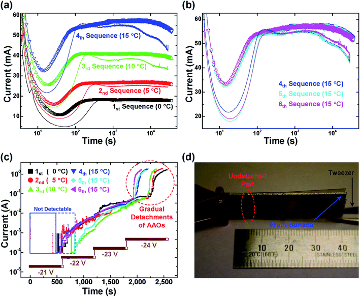
Fig. 2a and b show the current–time (I–t) characteristic behaviors in the two-step SMSAs from 1st to 6th sequence, applied on a same Al substrate with respect to the various electrolyte temperatures. All the I–t characteristic curves of the Pre-SMSAs exhibit more complicated variations comparing with those of the Main-SMSAs, because formations of nanopores initiated at irregularly distributed concaves on the non-textured (i.e., electropolished) Al surfaces, which would merge to a stable formation of regular nanopores array resulting in the texturing effects.3,4,38 As shown in Fig. 2a, distinct enhancements of the current levels in the whole I–t characteristic curves of the two-step SMSAs in each sequence were observed with increasing the electrolyte temperature. The current in anodization originates from electron transfer due to the exothermic oxidation/alumina dissolution at Al/Al2O3 and Al2O3/electrolyte interfaces as well as transport of the corresponding ions (e.g., Al3+, O2−, and OH−) through the alumina and electrolyte.3,4,38,54 So, low temperature of the acidic electrolyte would suppress the chemical reactions and ion transport inducing low current level, which directly influence on growth rate and dimensional characteristics of the AAOs (this will be discussed more details in later).Owing to viscous flow4,73 and volume expansion4,38,39,54,55 during the simultaneous growths of plural AAOs, boundaries between barrier oxides in the adjacent (perpendicular) AAOs were formed along the multi-edges, and diagonally extended inside the Al substrate. As the SMSA proceeded, total anodizing area is gradually reduced and mechanical stresses due to the volume expansions keep storing at multi-interfaces between the AAOs and Al substrate. In addition, earlier formed boundaries evolved into voids.67 As observed in Fig. 2a and b, gradual decrease of the current with respect to the anodizing time would be suggested as a peculiar feature of the SMSA procedure (see also Fig. S1a and b†), which could be attributed to the reduction of the total anodizing area as well as suppression of the ion transport by the stored stresses. In addition, degree of the current reduction depended on the electrolyte temperature, because of the slower AAO growth rate in lower temperature of the electrolyte, which generates less volume expansion and mechanical stresses. It should be noted that any clear peak, related to an equilibrium state of the boundaries formation in sulfuric acid electrolyte,67 was not found in the I–t characteristic curves of the Main-SMSAs in Fig. 2a and b. This result can be explained that AAOs fabricated in oxalic acid electrolyte exhibit more elastic nature than those from sulfuric acid,4,41 which might absorb the mechanical stresses.
Fig. 2c presents the I–t characteristic behaviors in the SRBs-detachments of the AAOs from 1st to 6th sequence and a representative voltage–time (V–t) profile of the SBRs used in 1st detaching procedure. Current was not detectable at the early stage of the detachment (blue boxes in Fig. 2c) due to the lower limit of resolution in our system (≥0.1 mA) indicating that the every immersed surfaces of the Al substrate were fully covered with insulating AAOs, and the narrow voids along the boundaries did not reach the Al edges. After appearing the current at the end of the beginning RB of −21 V (or in the middle of the next RB of −22 V for 3rd and 5th detachments), it was gradually increased with increasing the RB stair-likely. Coincidentally, bubbles were created along the multi-edges only (not from middle of surfaces), which were intensified with respect to the current increment. Then, gradual detachments of plural AAOs occurred in the final RB of −24 V, as depicted by red-dashed circle in Fig. 2c. The I–t characteristics of the SRBs-detachments in oxalic acid electrolyte exhibited quite different behaviors comparing with those in sulfuric acid electrolyte, for example, abrupt enhancements of current indicating instantaneous detachments of the AAOs67 was not observed in Fig. 2c. These results including gradual detachments of the AAOs would be ascribed to an elastic nature of the AAOs fabricated in oxalic acid electrolyte, which might counteract a SRBs detaching mechanism correlated with stress-release due to the dissolution of the boundaries.67 However, permeation of the acidic electrolyte as well as extension of the bubbling effects into the inner areas along the multi-interfaces between each AAO and corresponding Al surface were also observed, analogous to the SRBs-detachment in the sulfuric acid electrolyte. For comparison, we applied a constant RB of −24 V or larger absolute intensity to the AAO fabricated in the same condition of 4th sequence, which detached some parts of the AAO with irregular shapes, which was not even reproducible. In addition, remaining part as well as the other AAOs were not detached even increasing the applied time more than 1 h, because the constant RB interacted violently with the AAO-peeled Al surface rather than boundaries in the acidic electrolyte, which might affect the Al surfaces adversely in the aged acidic electrolyte with abundant Al3+ ions. When a constant RB of −21 V was applied, the current did not increase even holding it more than 2 h, and detachment of the AAO did not occur.
Fig. 2d shows a photograph of the as-detached AAOs and remaining Al substrate, which was taken right after SRBs-detachment. By careful spreading the AAOs with an aid of tweezer, it was observed that the upper part of the detached AAO still connected to the remaining Al substrate as depicted by red-dashed ellipse in Fig. 2d, because about three quarters of the Al substrate was immersed in the oxalic acid electrolyte during the SMSAs and SRBs detachment. The undetached part was mechanically broken for complete separation of the AAO. SRBs could optimally accelerate the dissolution of boundaries formed by SMSAs, which would be a key factor for the simultaneous detachments of the plural AAOs as continuous single pieces with identical length and width of the corresponding Al surfaces. It should be noted that the Pre-AAOs were also detached well through the SRBs (see the Fig. S2†), which can be utilized depending on the applications, such as effective filtrations for ultra-fine dust or water–oil separation, etc.
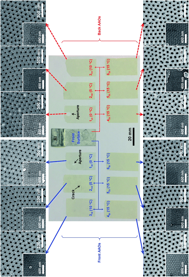
Fig. 3 presents the outputs resulted from the six times repetitions of the AAO fabricating sequences on a single Al substrate. The plural AAOs showing yellowish colors were obtained as continuous single pieces with equal dimensions of front and back surfaces (see the Fig. S3 and S4† for the detached AAOs from two sides and bottom surfaces). However, an aperture (i.e., perforated area) was found in the AAO detached from the front surface under the 1st sequence at 0 °C (hereafter referred as 1st-Front-AAO) and 1st-Back-AAO, respectively. In addition, a crack was also identified in the 2nd-Front-AAO. These defects might be originated from the relatively thinner thicknesses of the AAOs due to the lower electrolyte temperatures indicating that SRBs detaching condition should be further optimized for thinner AAOs, which will be investigated more details in Section 3.2. The hue and saturation of the AAO colors grew richer from almost transparent (0 °C) to vivid yellowish (15 °C) tones with respect to the electrolyte temperatures, which was also attributed to the anion-infiltrated anodization mechanism.4,66 Periodic arrangements of the nanopores were well identified in all the scanning electron microscope (SEM) images implying that our SMSAs and SRBs-detachments functioned independent of not only the surface location but also applied sequence. As increasing the electrolyte temperatures from 0 °C (1st) to 15 °C (4th), the DP0 of the AAOs was also increased, whereas the DP0 of the AAOs fabricated under the fixed electrolyte temperature of 15 °C (4th–6th) remained almost same. These results were well agreed with Fig. 2a and b, because the DP0 was strongly correlated with the temperature-dependent and electric field-assisted local dissolution of alumina,3,4,54 which would be one of the main components in anodizing current. However, the Dint of all the AAOs did not much changed regardless of the electrolyte temperatures. The insets of the SEM images in Fig. 3 showed the barrier oxide layers having a honeycomb structure composed of hexagonal unit cells with almost constant area, which also supported the invariant Dint. In addition, this result pointed out that a cleavage plane through the SRBs-detachment in the oxalic acid electrolyte was also beneath the barrier oxide, just as in the sulfuric acid electrolyte.67 The remaining Al substrate, experienced total six sequences of the AAO fabrication, still had a thickness of ∼125 μm.
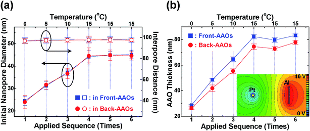
Quantitative investigations of the characteristic dimensions, such as DP0, Dint, and thicknesses, are compared in Fig. 4 with respect to the electrolyte temperatures and applied sequences. The averaged DP0 of the 1st-Front-AAO was measured 24.5 ± 2.08 nm. As shown in Fig. 4a, those of 2nd-Front-AAO (5 °C), 3rd-Front-AAO (10 °C), and 4th-Front-AAO (15 °C) were linearly increased to be 31.3 ± 1.84 nm, 37.3 ± 1.40 nm, and 44.2 ± 2.71 nm, respectively. The 5th-Front-AAO and 6th-Front-AAO exhibited almost comparable DP0 of 44.9 ± 1.72 nm and 45.2 ± 1.89 nm due to the same electrolyte temperature of 15 °C. The averaged Dint of all the AAOs lied between 96.7 ± 2.24 nm (1st-Back-AAO) and 98.1 ± 2.64 nm (5th-Front-AAO), which were not much influenced by the electrolyte temperatures. These results implied that the Dint and unit cell size were mainly determined by the anodic voltage and electrolyte concentration. Considering the error bars in Fig. 4a, differences of the DP0 and Dint seemed to be negligible between Front- and Back-AAOs. Fig. 4b describes the variations of the averaged thicknesses of both Front- and Back-AAOs as a function of the electrolyte temperature, which show very analogous behaviors to those of DP0. All the results matched well the I–t characteristics in Fig. 2 and SEM images in Fig. 3. It should be noted that all the thicknesses of Back-AAOs were placed below those of Front-AAOs. As shown in the inset of Fig. 4b, equipotential lines near the front surface of the Al substrate were distributed more densely, whereas those near the back surface were spread sparsely. Therefore, the strength of the electric field would be different at each surface, which could be the reason for relatively thinner thicknesses of Back-AAOs. The numeric values of the characteristic dimensions in the as-prepared the AAOs are well agreed with those in previous reports on the conventional mono-surface MAs in oxalic acid electrolyte (see the Table S1†).6,38,39,55,57,60,65
3.2 AAO thickness dependent SRBs detaching behaviors
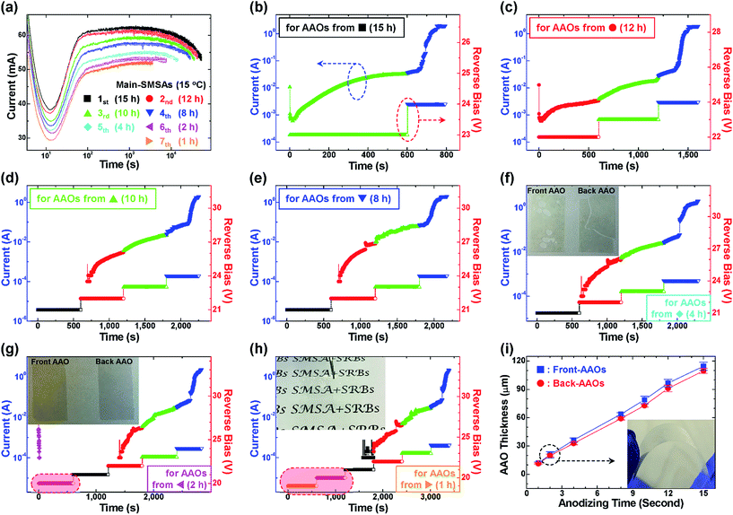
As observed in Fig. 3, SRBs consisting of 4 stairs (−21 V, −22 V, −23 V, and −24 V) exhibited a limited capability of detaching thin AAO, especially thinner than ∼50 μm, which resulted in perforated area and/or crack sometimes. Therefore, we further optimized the SRBs detaching conditions about various thicknesses of the AAOs. Fig. 5a shows the I–t characteristic curves of the Main-SMSAs with different anodizing times from 1 h to 15 h at fixed electrolyte temperature of 15 °C, which were repeatedly applied up to 7 sequences on a same Al substrate. Beside the gradual decrease of the current with respect to the anodizing time in the individual I–t characteristic curve, which was very analogous to Fig. 2a and b, the entire I–t characteristic curves were also decreased with increasing the number of the applied sequences ascribed to the reduction of the total anodizing area.Fig. 5b to h present V–t profiles (right axes) of SRBs used for Fig. 5a and corresponding I–t characteristic curves (left axes) during the SRBs-detachments. For thicker AAOs fabricated under the Main-SMSAs of 15 h and 12 h, the number of stairs in SRBs could be reduced to 2 (Fig. 5b) and 3 (Fig. 5c), respectively, and defect-free AAOs were well detached. Fig. 5d and e prove that SRBs with 4 stairs would be an optimal detaching condition for the AAO with a thickness more than ∼60 μm. However, when the same SRBs with 4 stairs were applied to sample from the Main-SMSA of 4 h, perforating and/or cracking happened in Front- and Back-AAO, respectively, as shown in the inset of Fig. 5f. These defects generation might be correlated with the AAO thickness and detaching speed. Considering the above results, SRBs detaching condition was modified for sample from the Main-SMSA of 2 h by adding a stair of −20 V at the beginning stage of detaching procedure (Fig. 5g), which could slow down the detaching speed. The photograph in the inset of Fig. 5g exhibits that defect-free (i.e., continuous single pieces) AAOs were successfully obtained with equal dimensions of the front and back surfaces, respectively. Fig. 5h demonstrates further extension of our detaching strategy for thinnest AAOs from the Main-SMSA of 1 h, which was accomplished through the SRBs with total 6 stairs from −19 V to −24 V. In addition, it shows highly transparent nature, and printed texts were clearly identified through the AAO as shown in the inset of Fig. 5h. The results indicate that lower intensity of stair in SRBs could induce more homogenous and stable dissolution of the boundaries, which plays a crucial role in the SRBs-detachment of thinner AAO.
In Fig. 5i, linear variation of the AAO thicknesses is observed with respect to the anodizing times, and differences between Front- and Back-AAOs were also confirmed just as in Fig. 4b (see the Table S2†). The inset photograph in Fig. 5i verifies that flexible nature appears in AAOs with relatively thinner thicknesses (black-dashed circle).
3.3 π-Conjugated polymer nanowires with various diameters
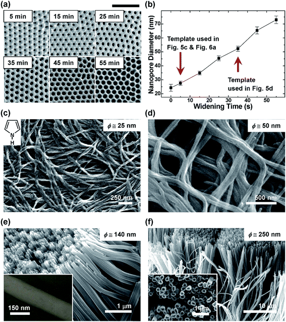
In order to control the DP in wider range, we chose the AAOs with smallest DP0 fabricated at 0 °C as a starting material for the pore-widening procedure. Fig. 6a shows the SEM images of the AAOs after pore-widening treatment with different times. With increasing the pore-widening time from 5 to 55 min, averaged DP of the AAO was also enlarged from 27.6 ± 1.48 nm to 72.9 ± 2.27 nm, as shown in Fig. 6 (see also Table S3†). The AAOs with the averaged DP of 27.6 ± 1.48 nm (pore-widening for 5 min) and 52.2 ± 1.84 nm (pore-widening for 35 min) were selected for synthesizing the nanomaterials, which were indicated by red arrows in Fig. 6b.The SEM images of the electrochemically synthesized, conducting PPy NWs with various diameters were presented in Fig. 6c–f, respectively. Open-end structures (i.e., tubular-like shape) identified in the Fig. 6e and inset of Fig. 6f were a typical feature observed in the PPy NWs,74 and transmission electron microscope (TEM) image shown in the inset of Fig. 6e proved the formation of NW with completely filled inside. The averaged diameters (ϕ) of the PPy NWs synthesized by using fabricated AAOs were estimated to be ∼25 nm and ∼50 nm, which were little bit smaller that DP of the AAOs owing to a tiny gap existing between hydrophilic AAO and hydrophobic organic materials.7,69 However, those of the PPy NWs synthesized by using purchased AAOs were estimated to be ∼140 nm and ∼250 nm, which were much larger than specifications provided by the manufacturer. This inconsistency was originated that nanopores in the purchased AAOs showed spheroid-like shape with non-uniform DP, where the DP at the middle of the nanopore would be larger than those at both ends, which would be appropriate for filtering applications.
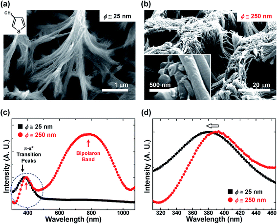
Fig. 7 exhibits the light-emitting P3MT NWs synthesized by using fabricated and purchased AAOs. As shown in Fig. 7a and b, distinct averaged diameters of ∼25 nm and ∼250 nm were clearly observed with respect to the corresponding DP of the AAOs, respectively. Fig. 7c shows the ultraviolet-visible (UV-Vis) absorption spectra the P3MT NWs dispersed in a chloroform solution. For the P3MT NWs with an averaged diameter of ∼250 nm, the π–π* transition peak and broad bipolaron band were observed at 390 nm and ∼780 nm, respectively.7–9,68 When the diameters of P3MT NWs were decreased from ∼250 nm to ∼25 nm, the π–π* transition peak was blue-shifted toward 380 nm, and became broadened, particularly enhancing its tail in shorter wavelength region, as shown in Fig. 7d, indicating the reduction of the π-conjugation length due to the confine synthesis within relatively narrow volume of the fabricated AAOs.8,74 In addition, the doping-induced bipolaron band was significantly decreased for the P3MT NWs with an averaged diameter of ∼25 nm, which could be utilized as active components in optoelectronic applications without further dedoping treatments68 (e.g., electrochemical reduction–oxidation7 or electron-beam irradiation,8,9,74 etc.). These result could be attributed to the dopants-assisted electrochemical polymerization mechanism75 and enhancement of the surface area resulted from the smaller diameters of the AAO, which could enable the dopant ions intercalated between the polymeric chains smearing out more easily by the counter ions (e.g., OH−) exchanging effects during dedoping phenomena.7–9,68,69,74
3.4 Humidity sensing performances: role of barrier oxide layer
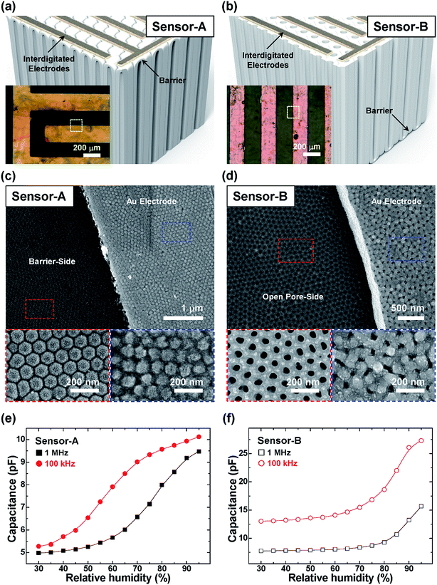
Fig. 8a and b show schematic structures of capacitive humidity sensors based on the as-prepared AAOs with barrier oxide layers, where the interdigitated electrodes located onto the barrier oxide layer (Sensor-A) or the opposite open-pore side (Sensor-B), respectively. We would like to point out that the AAOs fabricated at 15 °C were chosen as sensing and frame materials, which have largest DP0 among our products, and do not go through the pore-widening procedure. As shown in the insets of Fig. 8a and b, the interdigitating structure of each electrode was well identified with the line width and distance between the adjacent lines of ∼200 μm, respectively. Fig. 8c and d exhibit the SEM images of each humidity sensor taken at the borders of the electrodes confirming the appropriate formations of the electrodes on the desired positions, which also verified in the magnified SEM images shown in the corresponding insets. Fig. 8e and f compares capacitance variations of two AAO sensors with respect to RH by using linear–linear scale plots. Sensor-A showed quite linear responsive variations of capacitance in the intermediate RH regions (40–70% under 100 kHz and 60–90% under 1 MHz), whereas the capacitance were varied only in the high RH region (≥75%) in Sensor-B, which was comparable to the previous reports at relatively high frequencies.22–27 The barrier oxide layer in Sensor-A might play an important role for storing the humidity inside the nanopores more effectively resulting in the linear variation of the capacitance even in the relatively low RH region without applying sophisticated add-ons,70 for examples magnetic field28 or water-sensitive sol–gel materials (e.g., polyethylene glycol).72 In Sensor-B, the interdigitated electrodes occupied some portion of the open-pore side, which would reduce an accessibility of humidity into and/or out of the nanopores. It is expected that the performances of our humidity sensors would be further improved by optimizing dimensional properties of the AAO and electrodes.28,70,72 These results represent a superior applicability of our devices such that one can choose the structure of the humidity sensors with respect to the interesting region of the RH. Moreover, our strategy, excluding the procedure for removing the barrier oxide layer, also exhibits another advantage in terms of the simplicity about device fabrication.4. Conclusions
In summary, we successfully demonstrated two-step SMSAs and SRBs-based detachment techniques in an oxalic acid electrolyte for a facile and eco-friendly technique to fabricate AAOs, which can be extended for mass-production with efficient usage of natural resources by repeating the unit sequence to a single Al substrate. Dimensional characteristics (DP0 and thickness) of the AAOs were controlled through the fabricating conditions, such as the electrolyte temperature and anodizing time, whereas Dint maintained almost identical value, which was mainly determined by the anodic voltage and electrolyte concentration. For diverse applications of the AAOs, conducting PPy and light-emitting P3MT NWs with various diameters were electrochemically synthesized using fabricated and purchased AAOs. Capacitive humidity sensor having interdigitated electrodes on the barrier oxide layer of the AAO exhibited a linear response in the intermediate region of RH. As a next step for elevating the yield of AAO fabrication moreover, we are trying to combine our SMSAs and SRBs-detachment with HA condition, which could enrich the potential applicability of the AAOs in terms of extending controllability to DP0 and Dint and their periodic arrangements.Acknowledgements
This research was supported in part by the National Research Foundation of Korea (NRF) grant funded by the Korea government (MSIP) (No. 2016R1C1B1016344, 2015R1A5A1037548, and 2014M3A9D7070732). Support by the Inha University Research Grant (INHA-51761) is gratefully acknowledged.References
- F. Keller, M. Hunter and D. Robinson, J. Electrochem. Soc., 1953, 100, 411–419 CrossRef CAS.
- J. W. Diggle, T. C. Downie and C. W. Goulding, Chem. Rev., 1969, 69, 365–405 CrossRef CAS.
- J. P. O'Sullivan and G. C. Wood, Proc. R. Soc. London, Ser. A, 1970, 317, 511–543 CrossRef.
- W. Lee and S.-J. Park, Chem. Rev., 2014, 114, 7487–7556 CrossRef CAS PubMed.
- H. Masuda and K. Fukuda, Science, 1995, 268, 1466–1468 CAS.
- H. Masuda and M. Satoh, Jpn. J. Appl. Phys., 1996, 35, L126–L129 CAS.
- D. H. Park, H. S. Kim, M. Y. Jeong, Y. B. Lee, H. J. Kim, D. C. Kim, J. Kim and J. Joo, Adv. Funct. Mater., 2008, 18, 2526–2534 CrossRef CAS.
- Y. K. Hong, D. H. Park, S. K. Park, H. Song, D. C. Kim, J. Kim, Y. H. Han, O. K. Park, B. C. Lee and J. Joo, Adv. Funct. Mater., 2009, 19, 567–572 CrossRef CAS.
- Y. K. Hong, D. H. Park, S. G. Jo, M. H. Koo, D. C. Kim, J. Kim, J. S. Kim, S. Y. Jang and J. Joo, Angew. Chem., Int. Ed., 2011, 50, 3734–3738 CrossRef CAS PubMed.
- T.-C. Chan, Y.-M. Lin, H.-W. Tsai, Z. M. Wang, C.-N. Liao and Y.-L. Chueh, Nanoscale, 2014, 6, 7332–7338 RSC.
- S. Ghosh, T. Maiyalagan and R. N. Basu, Nanoscale, 2016, 8, 6921–6947 RSC.
- U. Khan, M. Irfan, W. J. Li, N. Adeela, P. Liu, Q. T. Zhang and X. F. Han, Nanoscale, 2016, 8, 14956–14964 RSC.
- H. Wang, T. Chang, X. Li, W. Zhang, Z. Hu and A. M. Jonas, Nanoscale, 2016, 8, 14950–14955 RSC.
- T. Kyotani, W. Xu, Y. Yokoyama, J. Inahara, H. Touhara and A. Tomita, J. Membr. Sci., 2002, 196, 231–239 CrossRef CAS.
- X. Chen, M. Qiu, H. Ding, K. Fu and Y. Fan, Nanoscale, 2016, 8, 5696–5705 RSC.
- S. Dervin, D. D. Dionysiou and S. C. Pillai, Nanoscale, 2016, 8, 15115–15131 RSC.
- K. Han, L. Heng, L. Wen and L. Jiang, Nanoscale, 2016, 8, 12318–12323 RSC.
- J. Kim, Y. H. Kim, S. H. Choi and W. Lee, ACS Nano, 2011, 5, 5242–5248 CrossRef CAS PubMed.
- Z. Zeng, X. Huang, Z. Yin, H. Li, Y. Chen, H. Li, Q. Zhang, J. Ma, F. Boey and H. Zhang, Adv. Mater., 2012, 24, 4138–4142 CrossRef CAS PubMed.
- J. Yang, M. Ma, L. Li, Y. Zhang, W. Huang and X. Dong, Nanoscale, 2014, 6, 13301–13313 RSC.
- N. Lim, Y. Pak, J. T. Kim, Y. Hwang, R. Lee, Y. Kumaresan, N. Myoung, H. C. Ko and G. Y. Jung, Nanoscale, 2015, 7, 13489–13494 RSC.
- V. K. Khanna and R. K. Nahar, Appl. Surf. Sci., 1987, 28, 247–264 CrossRef CAS.
- E. C. Dickey, O. K. Varghese, K. G. Ong, D. Gong, M. Paulose and C. A. Grimes, Sensors, 2002, 2, 91–110 CrossRef CAS.
- Y. Kim, B. Jung, H. Lee, H. Kim, K. Lee and H. Park, Sens. Actuators, B, 2009, 141, 441–446 CrossRef CAS.
- R. K. Nahar, Sens. Actuators, B, 2000, 63, 49–54 CrossRef CAS.
- Z. He, L. Yao, M. Zheng, L. Ma, S. He and W. Shen, Phys. E, 2010, 43, 366–371 CrossRef CAS.
- K. Sharma and S. S. Islam, Sens. Actuators, B, 2016, 237, 443–451 CrossRef CAS.
- S. W. Chen, O. K. Khor, M. W. Liao and C. K. Chung, Sens. Actuators, B, 2014, 199, 384–388 CrossRef CAS.
- J. Chen, S. Wang, L. Ding, Y. Jiang and H. Wang, J. Membr. Sci., 2014, 461, 22–27 CrossRef CAS.
- Y. K. Ahn, J. Park, D. Shin, S. Cho, S. Y. Park, H. Kim, Y. Piao, J. Yoo and Y. S. Kim, J. Mater. Chem. A, 2015, 3, 10715–10719 CAS.
- Y. Gao, Y. Lin, J. Chen, Q. Lin, Y. Wu, W. Su, W. Wang and Z. Fan, Nanoscale, 2016, 8, 13280–13287 RSC.
- J. Hu, C.-F. Sun, E. Gillette, Z. Gui, Y. Wang and S. B. Lee, Nanoscale, 2016, 8, 12958–12969 RSC.
- S. B. Lee, D. T. Mitchell, L. Trofin, T. K. Nevanen, H. Söderlund and C. R. Martin, Science, 2002, 296, 2198–2200 CrossRef CAS PubMed.
- F. Matsumoto, K. Nishio and H. Masuda, Adv. Mater., 2004, 16, 2105–2108 CrossRef CAS.
- L. Qin, M. J. Banholzer, J. E. Millstone and C. A. Mirkin, Nano Lett., 2007, 7, 3849–3853 CrossRef CAS PubMed.
- K. Kim, M.-C. Jo, S. Jeong, L. Palanikumar, V. M. Rotello, J.-H. Ryu and M.-H. Park, Nanoscale, 2016, 8, 11949–11955 RSC.
- H. Masuda, F. Hasegwa and S. Ono, J. Electrochem. Soc., 1997, 144, L127–L130 CrossRef CAS.
- F. Li, L. Zhang and R. M. Metzger, Chem. Mater., 1998, 10, 2470–2480 CrossRef CAS.
- K. Nielsch, J. Choi, K. Schwirn, R. B. Wehrspohn and U. Gösele, Nano Lett., 2002, 2, 677–680 CrossRef CAS.
- S. Z. Chu, K. Wada, S. Inoue, M. Isogai and A. Yasumori, Adv. Mater., 2005, 17, 2115–2119 CrossRef CAS.
- W. Lee, R. Ji, U. Gösele and K. Nielsch, Nat. Mater., 2006, 5, 741–747 CrossRef CAS PubMed.
- Y. Li, Z. Y. Ling, S. S. Chen and J. C. Wang, Nanotechnology, 2008, 19, 225604 CrossRef CAS PubMed.
- K. Schwirn, W. Lee, R. Hillebrand, M. Steinhart, K. Nielsch and U. Gösele, ACS Nano, 2008, 2, 302–310 CrossRef CAS PubMed.
- W. Lee, K. Schwirn, M. Steinhart, E. Pippel, R. Scholz and U. Gösele, Nat. Nanotechnol., 2008, 3, 234–239 CrossRef CAS PubMed.
- W. Lee, J. C. Kim and U. Cösele, Adv. Funct. Mater., 2010, 20, 21–27 CrossRef CAS.
- Y. B. Li, M. J. Zheng and L. Ma, Appl. Phys. Lett., 2007, 91, 073109 CrossRef.
- Y. Li, M. Zheng, L. Ma and W. Shen, Nanotechnology, 2006, 17, 5101–5105 CrossRef CAS.
- L. Yi, L. Zhiyuan, C. Shuoshuo, H. Xing and H. Xinhua, Chem. Commun., 2010, 46, 309–311 RSC.
- M. Norek, M. Dopierała and W. J. Stępniowski, J. Electroanal. Chem., 2015, 750, 79–88 CrossRef CAS.
- S. Ono, M. Saito and H. Asoh, Electrochem. Solid-State Lett., 2004, 7, B21–B24 CrossRef CAS.
- M. A. Kashi, A. Ramazani, M. Raoufi and A. Karimzadeh, Thin Solid Films, 2010, 518, 6767–6772 CrossRef CAS.
- C. Cheng and A. H. W. Ngan, Nanotechnology, 2013, 24, 215602 CrossRef PubMed.
- X. Qin, J. Zhang, X. Meng, L. Wang, C. Deng, G. Ding, H. Zeng and X. Xu, Surf. Coat. Technol., 2014, 254, 398–401 CrossRef CAS.
- O. Jessensky, F. Müller and U. Gösele, Appl. Phys. Lett., 1998, 72, 1173–1175 CrossRef CAS.
- A. P. Li, F. Müller, A. Bimer, K. Nielsch and U. Gösele, J. Appl. Phys., 1998, 84, 6023–6026 CrossRef CAS.
- H. Asoh, K. Nishio, M. Nakao, T. Tamamura and H. Masuda, J. Electrochem. Soc., 2001, 148, B152–B156 CrossRef CAS.
- S. Z. Chu, K. Wada, S. Inoue, M. Isogai, Y. Katsuta and A. Yasumori, J. Electrochem. Soc., 2006, 153, B384–B391 CrossRef CAS.
- W. Chen, J. S. Wu, J. H. Yuan, X. H. Xia and X. H. Lin, J. Electroanal. Chem., 2007, 600, 257–264 CrossRef CAS.
- L. Gao, P. Wang, X. Wu, S. Yang and X. Song, J. Electroceram., 2008, 21, 791–794 CrossRef CAS.
- J. J. Schneider, J. Engstler, K. P. Budna, C. Teichert and S. Franzka, Eur. J. Inorg. Chem., 2005, 2005, 2352–2359 CrossRef.
- J. H. Yuan, F. Y. He, D. C. Sun and X. H. Xia, Chem. Mater., 2004, 16, 1841–1844 CrossRef CAS.
- S. Zhao, K. Chan, A. Yelon and T. Veres, Nanotechnology, 2007, 18, 245304 CrossRef.
- E. Choudhary and V. Szalai, RSC Adv., 2016, 6, 67992–67996 RSC.
- A. Brudzisz, A. Brzózka and G. D. Sulka, Electrochim. Acta, 2015, 178, 374–384 CrossRef CAS.
- T. Yanagishita and H. Masuda, Electrochim. Acta, 2015, 184, 80–85 CrossRef CAS.
- F. Le Coz, L. Arurault and L. Datas, Mater. Charact., 2010, 61, 283–288 CrossRef CAS.
- Y. K. Hong, B. H. Kim, D. I. Kim, D. H. Park and J. Joo, RSC Adv., 2015, 5, 26872–26877 RSC.
- Y. K. Hong, D. H. Park, S. H. Lee and J. Joo, Adv. Polym. Sci., 2013, 259, 201–244 CrossRef CAS.
- D. H. Park, M. S. Kim and J. Joo, Chem. Soc. Rev., 2010, 39, 2439–2452 RSC.
- T. A. Blank, L. P. Eksperiandova and K. N. Belikov, Sens. Actuators, B, 2016, 228, 416–442 CrossRef CAS.
- J. Zhang, X. Liu, G. Neri and N. Pinna, Adv. Mater., 2016, 28, 795–831 CrossRef CAS PubMed.
- M. R. Mahboob, Z. H. Zargar and T. Islam, Sens. Actuators, B, 2016, 228, 658–664 CrossRef CAS.
- J. E. Houser and K. R. Hebert, Nat. Mater., 2009, 8, 415–420 CrossRef CAS PubMed.
- Y. K. Hong, D. H. Park, S. H. Park, S. K. Park and J. Joo, Appl. Phys. Lett., 2009, 94, 053111 CrossRef.
- S. Sadki, P. Schottland, N. Brodie and G. Sabouraud, Chem. Soc. Rev., 2000, 29, 283–293 RSC.
Footnotes |
| † Electronic supplementary information (ESI) available. See DOI: 10.1039/c6ra25201j |
| ‡ These authors contributed equally to this work. |
| This journal is © The Royal Society of Chemistry 2017 |

