 Open Access Article
Three-dimensional network of coaxial carbon nanotube/manganese oxides electrode for supercapacitors†
S. J. Cho‡
a,
R. Chen‡a,
M. Leeb,
Y. S. Kangc,
S. Leed and
H. Lee*ae
aDepartment of Chemistry, Hanyang University, Seoul 04763, Korea. E-mail: haiwon@hanyang.ac.kr
bCenter for Nanobio Integration & Convergence Engineering, National Nanofab Center, Daejeon 34141, Korea
cDepartment of Energy Engineering, Hanyang University, Seoul 04763, Korea
dDepartment of Advanced Materials Engineering, University of Suwon, Gyeonggi-do 18323, Korea
eInstitute of Nano Science and Technology, Hanyang University, Seoul 04763, Korea
First published on 4th January 2017
Abstract
A three-dimensional network of carbon nanotubes (3DNC) coaxially coated with manganese oxides (MnOx) is used as an electrode for supercapacitors. 3DNC serves as a stable and conductive framework for controlled electrochemical deposition (ECD), and provides sufficient voids for fast ionic transport and diffusion. The coated thin layer MnOx reduces ion diffusion and electron transport distance, enabling fast reversible faradic reactions.
As one of the most promising electrochemical energy storage materials, manganese oxides have been studied extensively as supercapacitor electrode materials due to their low cost, non-toxicity and theoretically high capacity of about 1370 F g−1.1–10 In particular, low dimensional nanostructured MnOx with different morphologies has been developed as an electrode material and showed its advantages in charge storage capability.4,9,11–15 However, its intrinsic poor electrical conductivity is a current drawback to utilize MnOx as a high-rate performance supercapacitor.1,3–5,7 To overcome this problem, an effective way is to incorporate MnOx with other metal elements (Ni, Ru, Al, Sn and Pb etc.)6,7 or porous, high surface area and conductive nanostructures such as carbonaceous sphere,16 carbon nanotubes,17 graphene18 and conductive polymers.19 Among those for advanced metal oxide-based hybrid nanostructure design, coaxial thin layer structure with ordered nanostructure arrays is considered as one of promising approaches for achieving the goal. Previous research has shown only a very thin layer of metal oxide material (several tens of nanometers from the surface) participated in the redox reaction.20 Hence, coaxial thin layer structure could allow cations to intercalate into entire active materials and shorten electron transport distance inside the active materials. Yamauchi Y. et al.17 reported on the development of multi-walled carbon nanotube–manganese oxide core–shell structures utilized for asymmetric supercapacitor applications which shows a specific capacitance (Csp) of 185 F g−1 at a scan rate of 5 mV s−1. Ordered nanostructure array is also an excellent candidate in aspect of providing a conductive path way not only for electron transport but also for resolving the ionic diffusion and transportation issues of supercapacitor electrodes. Zhu S. J. et al.21 reported the development of coaxial mesoporous manganese dioxide/amorphous carbon nanotubes arrays for advanced asymmetric supercapacitors which exhibit the optimized pseudocapacitance performance (362 F g−1) with good cycling stability, and ideal rate capability. Ionic diffusion and transportation are critical points to improve superior energy density, power density and charge efficiency due to shorter diffusion length in void volume.22,23 Longer life cycle and stronger volume retention during the charge and discharge process can be obtained through the nanostructures. Here, we demonstrate a coaxial thin layer MnOx hybrid nanostructure array for high performance MnOx supercapacitors.
In our previous research works, three-dimensional network of carbon nanotubes (3DNC) on pillar structures have been developed.24–29 As demonstrated, 3DNC has a hierarchically arrayed structure with interconnected CNTs between ordered arrays of Si pillars.28 Because of its unique structural properties, 3DNC has been applied to many applications such as catalysis,26 colorimetric sensor,25 gas sensor,27 strain sensor,30 microfluidic platform,28 cell seeding platform,24 and surface-enhanced Raman scattering.29,31 The CNTs interconnected between ordered Si pillars are stable during electrochemical reactions and the 3DNC structure provides controlled voids for ionic diffusion onto the surface of active materials. It would be significant to study the capacitance performance by incorporating energy storage materials like MnOx.
In this work, 3DNC coaxially coated with MnOx is used as an electrode for supercapacitor. The 3DNC structure is not only served as a stable and conductive framework for controlled electrochemical deposition (ECD) of MnOx and a current collector for charge/discharge, but also provides sufficient voids for fast ionic transport between CNTs and ionic diffusion onto the surface of active materials. Simultaneously, the coated thin layer MnOx reduces the distance of ion diffusion and electron transport, enabling fast and reversible faradic reactions.
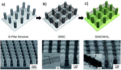
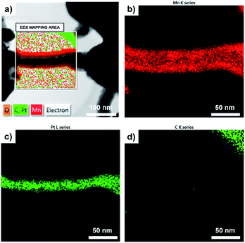
The schematic diagram of a fabrication process of 3DNC/MnOx and its corresponding scanning electron microscope (SEM) images are presented in Fig. 1. Amorphous carbon nanotubes on bare Si wafer (2DNC) was synthesized under the same condition for comparison and their SEM images are shown in Fig. S1.† The pristine Si pillars shown in Fig. 1a have a diameter of 1.0 μm and height of 3.0 μm, respectively. Fig. 1b describes that most CNTs were tangled on both the sides and tops of pillars, and some CNTs were suspended between pillars after synthesizing CNTs. The insert image of TEM in Fig. 1b verifies the multi-walled carbon nanotube grown on the Si pillar structure with average diameter of 25.1 nm. Before coating MnOx, a thin layer of Pt was firstly coated on the synthesized 3DNC using ion sputter. The Pt plays an important role in combining CNTs and target MnOx. As demonstrated in previous work,26 Pt coating is an essential step to improve the mechanical strength and maintaining the morphology of the 3DNC structures as well as enhancing electron transportation and adhesion between 3DNC and MnOx. Fig. 1c shows the SEM image of 3DNC coated with MnOx. After 3 min deposition of MnOx, the original 3D network morphology is still preserved and the diameter of CNTs is increased obviously. The inset TEM image clearly presents CNTs as a backbone were well coated with Pt and another thin layer which is composed of amorphous MnOx with a thickness of 5–10 nm. The average diameter of the CNT and MnOx coaxial composite bundles is around 43.1 nm. EDX elemental mapping is introduced for confirming the coaxial structure. In Fig. 2a a 3DNC/MnOx bundle is selected as the mapping area and then O, C, Pt and Mn elements are scanned. Fig. 2b and c clearly show that Mn and Pt elements are distributed at the bundle outside layer and inner core, respectively. However, C element from CNT is hardly to be detected in the bundle as shown in Fig. 2d. The reason could be that the covered Pt layer blocks or disturbs the signals from inner CNT. By comparing different MnOx deposition time, 3 min coating shows best performance. Details are explained in Fig. S2 and S3.†
 | ||
| Fig. 1 Schematic illustration of 3DNC/MnOx fabrication process and SEM images of (a) pristine Si pillar substrate, (b) as synthesized 3DNC and (c) 3DNC/MnOx. | ||
 | ||
| Fig. 2 (a) EDX elemental mapping of 3DNC/MnOx coaxial bundle; (b) Mn element, (c) Pt element and (d) C element mapping at the selected area. | ||
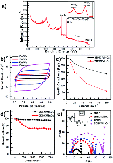
For a better understanding of the chemical composition and oxidation state of Mn, 3DNC/MnOx was characterized by X-ray photoelectron spectroscopy (XPS) as shown in Fig. 3a. Peaks of Mn 2p, O 1s, and C 1s are observed and the insert shows two peaks located at 654.2 eV and 642.6 eV, which are attributed to Mn 2p1/2 and Mn 2p3/2, respectively. Those results are in good agreement with previously reported data.1,2,32 Beyond coaxial and uniform coating, the oxidation state and electrochemical performance of MnOx can be controlled by changing pulse intervals in deposition. The pseudocapacitance value of MnOx is affected by Mn oxidation number. Since one alkali ion reacts with one MnOx molecule, MnO2(IV) has the highest ideal pseudocapacitance (1370 F g−1). Because MnOx is produced by reducing a permanganate ion in this experiment, the deposition of MnOx with higher oxidation number requires lower voltage.33 During constant current deposition, the applied voltage increases automatically as deposition time increases. This is because permanganate ion consumption occurs near the electrode, and higher voltage is required to deposit MnOx constantly. To refill consumed ions, the ECD process is carried out with intervals of zero current for free diffusion of permanganate ions. Ion diffusion is more considerable for three-dimensional structures due to larger diffusion voids. Three samples are prepared with 1 s deposition time and diffusion times of 15, 30, 60 s, per cycle. The oxidation state of MnOx is calculated using the peak height ratio of XPS spectra. The oxidation number of deposited MnOx is determined by the peak height ratio of Mn 2p3/2 versus O 2p (Table S1†). The peak height ratios of each sample are 1.03, 1.01 and 0.99 (Fig. S4†), with Csp of 190, 248 and 294 F g−1, respectively, at a scan rate of 10 mV s−1. Thus, 60 s diffusion time shows the best Csp value. While the peak height ratio approaching 0.95, more and more manganese dioxide is produced and the pseudo-capacitance of MnOx could be improved.34
To verify the electrochemical performance of 3DNC/MnOx, CV was conducted. The CV curves of 3DNC/MnOx (Fig. 3b) are closer to a rectangular shape and a mirror image at each scan rate than those of 2DNC/MnOx (Fig. S1c†). For 3DNC/MnOx, the shape of MnOx CV curves did not change significantly with the increase of scan rate, indicating the better capacitive behavior. Fig. 3c shows Csp values at different scan rates. The calculated Csp values of 3DNC/MnOx are 294, 261, 225 and 188 F g−1 at scan rates of 10, 20, 50 and 100 mV s−1, respectively, which are larger than those of 2DNC/MnOx at the same scan rate (Fig. S1c†). At low scan rate 10 mV s−1, the Csp values of these two materials show a small difference. However, when scan rate increases, the Csp value of 2DNC/MnOx is decreased more dramatically than 3DNC/MnOx. By comparing the SEM images of 3DNC/MnOx (Fig. 1c), the CNTs in 2DNC/MnOx (Fig. S1a†) are tightly connected or touched with adjacent ones. In this case, the large amount of voids obtained in 3DNC/MnOx structure promoted the ion diffusion and transfer speed between electrolyte and electrode and finally the capacitive performance was improved.
The cycle stability was confirmed for 2000 cycles at scan rate of 100 mV s−1. Fig. 3d shows the life cycle test of 3DNC/MnOx and 2DNC/MnOx. The Csp of 3DNC/MnOx retains about 96% of its initial capacitance even after 2000 cycles while 2DNC/MnOx retains only 72%. Fig. S5† compares the morphology of 3DNC/MnOx coaxial bundles before and after 2000 cycles test. There are no significant change could be observed except after life cycle test the 3DNC/MnOx surface becomes rougher which could be attributed to the intercalation and deintercalation of electrolyte cations. Hence, 3DNC/MnOx shows better stability and reversible capacitive behavior.
In addition, electrochemical impedance spectroscopy (EIS) was also carried out to understand the electrode resistance and ion-transfer behavior of the electrode materials (Fig. 3f). The proposed equivalent circuit for the measured impedance data is shown in the inset of Fig. 3f, where Rs is the internal resistance, Rct is faradic charge transfer resistance, CPE is the double-layer capacitance, and Zw is the electrolyte resistance.2,9,20,35 Typically the semi-circle in medium frequency regions reflects the Rct. Before coating MnOx, the Rct value of 3DNC (23.6 Ω) was much smaller than that of the 2DNC electrode (65.5 Ω). It should be attributed to the 3D network of 3DNC, which benefits the charge transfer between the electrode surface and the electrolyte. After coating MnOx, the Rct of 3DNC/MnOx and 2DNC/MnOx increased to 54.9 Ω and 82.8 Ω due to the poor conductivity of MnOx. However, the Rct value of 3DNC/MnOx was still much smaller than that of the 2DNC/MnOx electrode.
In the low frequency region, the slope of the curve represents the Zw, which is related to electrolyte diffusion in the porous electrode and proton diffusion in the active materials.35 As shown in Table 1, the Zw value of 3DNC (11.7 Ω) and 3DNC/MnOx (11.9 Ω) were smaller than those of the 2DNC (15.3 Ω) and 2DNC/MnOx (20.3 Ω) electrode, respectively. Those results were attributed to the unique hierarchical 3D structure based on Si pillar structure, which provided better electrolyte ion diffusion during fast charge and discharge processes.
| Parameter | Fitting value [Ω] | |||
|---|---|---|---|---|
| 3DNC | 3DNC/MnOx | 2DNC | 2DNC/MnOx | |
| Rct | 23.6 | 54.9 | 65.5 | 82.8 |
| Zw | 11.7 | 11.9 | 15.3 | 20.3 |
In conclusion, we coaxially deposited MnOx on a silicon pillar assisted 3DNC using an ECD process for supercapacitor application. The Csp of 3DNC/MnOx is about 294 F g−1 at 10 mV s−1 and the capacitance retention after 2000 cycles is as high as 96%. The 3DNC structure provides not only a better ion and electron transfer pathway but also larger contact area and voids for electrolyte ion diffusion during fast charge and discharge processes. This unique nanostructure contributes to fast and reversible supercapacitor applications.
Acknowledgements
The authors thank the National Research Foundation of Korea for financial support (2012M3A7B4035286, 2012R1A6A1029029, and 2016K1A4A3914691). Funding was also provided by a g-rant (AOARD-124044) from the AFOSR/AOARD, USA. S.References
- M. Toupin, T. Brousse and D. Belanger, Chem. Mater., 2004, 16, 3184–3190 CrossRef CAS.
- X. Xie and L. Gao, Carbon, 2007, 45, 2365–2373 CrossRef CAS.
- H. Zhang, G. P. Cao, Z. Y. Wang, Y. S. Yang, Z. J. Shi and Z. N. Gu, Nano Lett., 2008, 8, 2664–2668 CrossRef CAS PubMed.
- H. Xia, J. K. Feng, H. L. Wang, M. O. Lai and L. Lu, J. Power Sources, 2010, 195, 4410–4413 CrossRef CAS.
- W. Wei, X. Cui, W. Chen and D. G. Ivey, Chem. Soc. Rev., 2011, 40, 1697–1721 RSC.
- J. Jiang, Y. Li, J. Liu, X. Huang, C. Yuan and X. W. Lou, Adv. Mater., 2012, 24, 5166–5180 CrossRef CAS PubMed.
- M. Zhi, C. Xiang, J. Li, M. Li and N. Wu, Nanoscale, 2013, 5, 72–88 RSC.
- B. Brown, I. A. Cordova, C. B. Parker, B. R. Stoner and J. T. Glass, Chem. Mater., 2015, 27, 2430–2438 CrossRef CAS.
- M. Huang, X. L. Zhao, F. Li, L. L. Zhang and Y. X. Zhang, J. Power Sources, 2015, 277, 36–43 CrossRef CAS.
- J. Park, B. Kang, B. Kim, J.-S. Suh, Y.-M. Huh and S. Haam, Nano Convergence, 2015, 2, 1–8 CrossRef.
- X. Lu, D. Zheng, T. Zhai, Z. Liu, Y. Huang, S. Xie and Y. Tong, Energy Environ. Sci., 2011, 4, 2915 CAS.
- L. Zhang, K. N. Hui, K. S. Hui and H. Lee, Electrochim. Acta, 2015, 186, 522–529 CrossRef CAS.
- Y. Zhang, L. A. Huff, A. A. Gewirth and K. S. Suslick, Part. Part. Syst. Charact., 2015, 32, 899–906 CrossRef CAS.
- L. Zhang, K. N. Hui, K. S. Hui, X. Chen, R. Chen and H. Lee, Int. J. Hydrogen Energy, 2016, 41, 9443–9453 CrossRef CAS.
- L. Zhang, K. N. Hui, K. San Hui and H. Lee, J. Power Sources, 2016, 318, 76–85 CrossRef CAS.
- G. Nie, X. Lu, J. Lei and C. Wang, Electrochim. Acta, 2015, 180, 1033–1040 CrossRef CAS.
- R. R. Salunkhe, H. Ahn, J. H. Kim and Y. Yamauchi, Nanotechnology, 2015, 26, 204004 CrossRef PubMed.
- Y. S. Moon, D. Kim, G. Lee, S. Y. Hong, K. K. Kim, S. M. Park and J. S. Ha, Carbon, 2015, 81, 29–37 CrossRef CAS.
- C. H. Ng, H. N. Lim, Y. S. Lim, W. K. Chee and N. M. Huang, Int. J. Energy Res., 2015, 39, 344–355 CrossRef CAS.
- Y.-Y. Horng, Y.-C. Lu, Y.-K. Hsu, C.-C. Chen, L.-C. Chen and K.-H. Chen, J. Power Sources, 2010, 195, 4418–4422 CrossRef CAS.
- S. J. Zhu, J. Zhang, J. J. Ma, Y. X. Zhang and K. X. Yao, J. Power Sources, 2015, 278, 555–561 CrossRef CAS.
- J. Maier, Nat. Mater., 2005, 4, 805–815 CrossRef CAS PubMed.
- A. L. M. Reddy, S. R. Gowda, M. M. Shaijumon and P. M. Ajayan, Adv. Mater., 2012, 24, 5045–5064 CrossRef CAS PubMed.
- M. Park, E. Oh, J. Seo, M. H. Kim, H. Cho, J. Y. Choi, H. Lee and I. S. Choi, Small, 2016, 12, 1148–1152 CrossRef CAS PubMed.
- S. Lee, J. Lee, D. W. Lee, J. M. Kim and H. Lee, Chem. Commun., 2016, 52, 926–929 RSC.
- K. G. Lee, S. Lee, S. J. Chang, B. G. Choi, J. Seo, A. Sangalang, H. Kim do, T. J. Park, M. K. Lee, S. J. Lee and H. Lee, Small, 2015, 11, 4292–4297 CrossRef CAS PubMed.
- Y. D. Jo, S. Lee, J. Seo, S. Lee, D. Ann and H. Lee, J. Nanosci. Nanotechnol., 2014, 14, 9148–9151 CrossRef CAS PubMed.
- J. Seo, T. J. Lee, S. Ko, H. Yeo, S. Kim, T. Noh, S. Song, M. M. Sung and H. Lee, Adv. Mater., 2012, 24, 1975–1979 CrossRef CAS PubMed.
- M. K. Lee, J. Seo, S. J. Cho, Y. Jo, S. Kim, Y. Kang and H. Lee, Mater. Lett., 2012, 81, 9–12 CrossRef CAS.
- J. Seo, T. J. Lee, C. Lim, S. Lee, C. Rui, D. Ann, S. B. Lee and H. Lee, Small, 2015, 11, 2990–2994 CrossRef CAS PubMed.
- Y. Huang, A. R. Ferhan, S. J. Cho, H. Lee and D. H. Kim, ACS Appl. Mater. Interfaces, 2015, 7, 17582–17586 CAS.
- C. D. Wagner and G. E. Muilenberg, Handbook of x-ray photoelectron spectroscopy: a reference book of standard data for use in x-ray photoelectron spectroscopy, Physical Electronics Division, Perkin-Elmer Corp., 1979 Search PubMed.
- M. Pourbaix and M. Pourbaix, published 1974 by NACE, 1974, vol. 644.
- B. R. Strohmeier and D. M. Hercules, J. Phys. Chem., 1984, 88, 4922–4929 CrossRef CAS.
- C. Xia, Y. B. Xie, H. X. Du and W. Wang, J. Nanopart. Res., 2015, 17, 30 CrossRef.
Footnotes |
| † Electronic supplementary information (ESI) available. See DOI: 10.1039/c6ra25470e |
| ‡ S. J. Cho and R. Chen contributed equally to this work. |
| This journal is © The Royal Society of Chemistry 2017 |

