 Open Access Article
Creative Commons Attribution 3.0 Unported Licence
Selective catalytic reduction of NO with NH3 over Mo–Fe/beta catalysts: the effect of Mo loading amounts†
Jianlin Deng‡
a,
Jixing Liu‡a,
Weiyu Song‡a,
Zhen Zhao a,
Liang Zhao
 a,
Huiling Zhenga,
Alex Chinghuan Leeb,
Yongsheng Chenb and
Jian Liu
 *a
*a
aState Key Laboratory of Heavy Oil Processing, Beijing Key Lab of Oil & Gas Pollution Control, China University of Petroleum, 18# Fuxue Road, Chang Ping District, Beijing 102249, P. R. China. E-mail: liujian@cup.edu.cn; Fax: +86-10-69724721; Tel: +86-10-89732278
bDepartment of Mechanical and Automation Engineering, The Chinese University of Hong Kong, Shatin, New Territories, Hong Kong SAR, P.R. China
First published on 23rd January 2017
Abstract
A series of Mox–Fe/beta catalysts with constant Fe and variable Mo content were synthesized and investigated for selective catalytic reduction (SCR) of NOx with NH3. It was found that the Mo0.2–Fe/beta catalyst exhibited excellent activity, N2 selectivity and preferable resistance to H2O and SO2. The Mox–Fe/beta catalysts were characterized by various analytical techniques. TEM and SEM images showed that the addition of Mo could enhance the dispersion of iron oxides. The results of NH3-TPD and Py-IR indicated that the introduction of Mo resulted in a change of Brønsted acidity, which was associated with high-temperature SCR activity. XPS and XANES results showed that the introduction of Mo resulted in a change of Fe2+ content, which determined the low-temperature activity. DFT calculations showed the strong effects of Mo on the crystal structure, charge distribution and oxygen vacancy formation energy of iron oxides, which further explained the role of Mo in the catalyst behaviors during the SCR process.
1. Introduction
Nitrogen oxides such as NO, NO2 and N2O5 (NOx), originating from mobile and stationary sources, have been a major kind of air pollution. Due to numerous environmental issues (e.g. acid rain, photo chemical smog, ozone depletion and greenhouse effect) and serious harm to human health resulting from NOx, stringent regulations and great efforts have been made to confine NOx emissions.1,2 Nowadays, selective catalytic reduction with ammonia (NH3-SCR) is regarded as one of the most effective technologies for the removal of NOx.3In recent years, zeolite-based catalysts promoted by transition metals have attracted much attention for NH3-SCR.4,5 Different zeolite materials, such as MOR,6 MFI,7 CHA,8 and beta9 loaded with various transition metals have been investigated extensively on the SCR of NO with NH3. Among these zeolite-based catalysts, Fe-based catalysts exhibited excellent activity as an attractive candidate for SCR reaction.10,11 He et al.12 reported Fe-ZSM5 catalysts exhibited a fine low-temperature activity, and conclude that Fe2+ species are the active sites for NH3-SCR. Nedyalkova et al.13 suggested that the presence of Fe2+ should promote the NH3-SCR reaction at low temperatures. Further, they proposed that the capability of Fe2+ to interact with NO should be a key for high NH3-SCR activity at low temperatures. On the other hand, Long et al.14 suggested that Fe3+ should enhance oxidation of NO to NO2 and thus increase SCR activity at high temperature. Devadas et al.15 showed that the role of Fe3+ was to oxidize NO to NO2 at the high temperature, which was the rate-determining step for NH3-SCR. The presence of Fe3+ species could effectively decrease the unwanted NH3 unselective oxidation at high temperatures, resulting in high N2 selectivity.16 It can be conclude that Fe3+ species play a crucial role on NH3-SCR activity at high temperature. For Fe/beta catalysts, Fe2+ and Fe3+ have been found on the surface of catalysts as redox couple. It is difficult to enhance Fe2+ and Fe3+ loading amounts at same time, when the total Fe amounts in the catalyst are fixed. Thus, only narrow activity temperature window can be achieved for single iron-based zeolite catalysts.11 A study from Kobayashi et al.17 showed WO3–TiO2 catalysts possess a larger surface area and higher Brønsted acidity with the increasing of WO3 loading. WO3–TiO2 catalysts exhibit higher SCR activity at high temperatures, which is mainly attributed to the higher Brønsted acidity. Thus, Brønsted acidity is another factor on the high-temperature performance of NH3-SCR reaction. It is viable to introduce an extra metal ion to regulate the Fe2+ content and Brønsted acidity, which can further enhance catalytic activity of Fe-based catalysts from low to high temperature.
Molybdenum has been proved to be a promoter to enhance the surface acidity and the amount of active sites, and it has been widely used for oxide catalysts. For example, Liu et al.18 reported that the role of MoO3 is to promote the formation of Brønsted acidity, which contributes to the adsorption and activation of NH3 on the catalyst surface, resulting in the higher activity of Ce–MoO3/TiO2. Ding et al.19 proposed that the addition of Mo inhibit the growth of CeO2 particle size, improve the redox ability and increase the amount of surface acidity. It is favorable for the improvement of NH3-SCR performance.
In the present study, beta zeolite supported constant iron content and variable molybdenum amounts were prepared by a successive incipient-wetness impregnation. It was found that the addition of Mo showed a noticeable promoting effect on the activity of Fe/beta for NH3-SCR reaction at a wide temperature range. The effect of Mo on morphology of catalysts, Brønsted acidity and Fe2+ content was thoroughly studied. Furthermore, DFT calculations illustrate that the introduction of Mo results in the variation of Fe valence and affects the oxidation of NO to NO2. At the microscopic level, the interaction of iron and molybdenum, the oxygen vacancy formation energy and electronic properties of catalyst have been also investigated.
2. Experiment and calculation details
2.1 Catalyst preparation
Mox–Fe/beta catalysts were prepared by a successive incipient-wetness impregnation method using H-beta zeolite as the support. The synthesis method of H-beta was described in ESI.† In a typical synthesis, it was performed by mixing H-beta powders with appropriate amount of Fe(NO3)3 solution and treated in ultrasound for 4 h at room temperature. The precursor was dried at 110 °C for 12 h. Then, the samples were calcined at 500 °C for 5 h in the static air atmosphere and denoted as Fe/beta. The loading amounts of Fe for Fe/beta were maintained at 3% wt. Finally, Mox–Fe/beta catalysts with different Mo loading amounts were synthesized by the same method using (NH4)6Mo7O24·4H2O as the precursor and Fe/beta as the support. (x represents the weight percentage of Mo to beta, x = 0.1, 0.2, 0.5 and 1). For comparison, Mo0.2/beta catalyst were also synthesized by the same method using (NH4)6Mo7O24·4H2O as the precursor and beta as the support.2.2 Catalyst characterization
Powder X-ray diffraction (XRD) pattern was recorded on a Bruker D8 advance system with Cu Kα (λ = 0.15406 nm) radiation at 40 kV and 10 mA in the 2θ range of 5–70°.The surface morphology of the catalyst was collected by field emission scanning electron microscopy (FESEM) on a Quanta 200F instruments using accelerating voltages of 5 kV, in combination with an EDAX genesis 4000 energy-dispersive X-ray spectrometer (EDX).
The element content of as-prepared materials was determined by a Varian 715-ES inductively coupled plasma-atomic emission spectrometer (ICP-AES).
Transmission electron microscopy (TEM) micrographs were performed on a JEOL JEM-F20 electron microscope equipped with a field emission source operating at 200 kV. The average particle diameter was calculated from the mean diameter frequency distribution with the formula: d = ∑nidi/∑ni. Where, ni is the number of particles with particle diameter di in a certain range. The elemental local and mapping analyses were recorded by energy dispersive spectroscopy (EDS) using a Tecnai F20 electron microscope.
Temperature-programmed desorption of ammonia (NH3-TPD) measurement was carried out on a conventional flow apparatus. Prior to measurement, 0.1 g of sample was pretreated in N2 gas (30 mL min−1) at 600 °C for 0.5 h and then cooled down to room temperature. Next, the sample was exposed to a mixed gas (10% NH3/N2) flow of 30 mL min−1 for 0.5 h to ensure the sufficient adsorption of NH3. Before desorption, the sample was flushed in N2 gas for 1.5 h. Subsequently, NH3 desorption was performed in the range of 100–700 °C at a heating rate of 10 °C min−1 under a N2 flow of 30 mL min−1.
Pyridine-IR analysis was performed on a MAGNAIR 560 FT-IR instrument. The sample was dehydrated at 500 °C for 4 h under a vacuum of 1.3 × 10⁻³ Pa, followed by adsorption of pyridine vapor at room temperature and evacuated at different temperatures.
Temperature programmed reduction of hydrogen (H2-TPR) experiment was carried out in a home-made apparatus. Prior to reduction, the sample (50 mg) was treated from room temperature to 600 °C under a flow rate of 30 mL min−1 N2 and then cooled down to 60 °C in a purging N2 flow. The temperature programmed reduction process was performed in 30 mL min−1 flow of 10% H2/N2 at a ramp rate of 10 °C min−1 up to 900 °C.
X-ray photoelectron spectroscopy (XPS) experiment was conducted on a PerkinElmer PHI-1600 ESCA spectrometer equipped with Mg Kα (hν = 1253.6 eV) radiation. The binding energy was determined referenced to the C 1s peak of contaminant carbon (BE = 284.6 eV).
X-ray absorption near edge structure (XANES) spectra at Fe L3-edge (706.8 eV) were recorded in total electron yield mode on the BL27SU Beamline at Spring-8 in Japan.
2.3 Catalyst activity evaluation
Catalyst activity tests were conducted on a fixed-bed quartz micro-reactor at atmospheric pressure. The gas compositions were as follows: 500 ppm NO, 500 ppm NH3, 3 vol% O2, balance N2 and the gas flow rate was 500 mL min−1. The concentration of NOx (NOx = NO + NO2) in the inlet and outlet gas at steady-state was measured using a flue gas analyzer (Model-4000VM, SIGNAL international Ltd., UK), and NH3 and N2O was monitored by a NEXUS 670-FTIR spectrometer. NOx conversion was calculated according to the following equation (eqn (1)).
 | (1) |
N2 selectivity in SCR reaction was calculated by eqn (2)
 | (2) |
2.4 Calculational details
DFT calculations were performed with the PBE (Perdew–Burke–Ernzerhof)20 function using the Vienna Ab Initio Simulation Package (VASP).21 The spin-polarized calculations were performed. The projector augmented wave method (PAW) was used to describe the interaction between the ions and the electrons with the frozen-core approximation.22 The kinetic energy cutoff was 400 eV. All structures were relaxed until the forces acting over each atom were smaller than 0.05 eV Å−1 and electronic energies were converged within 10−4 eV. Owing to the 3d Fe electrons, hematite is a strongly correlated system in which Fe d- and O p-orbitals hybridize significantly. DFT has a strong tendency to delocalize d electrons, resulting in the underestimation of the band gap in metal oxides.23 The U and J terms describing the Coulomb and exchange interactions are always combined together in the form Ueff = U − J. The Ueff value (Ueff = 3.8) and bulk lattice parameter (a = b = 5.107 Å and c = 13.959 Å) are used.24Hematite (α-Fe2O3) has a corundum-type structure, and is the most stable and abundant iron oxide. Previous experimental and theoretical results reveal that Fe terminated Fe2O3 (001) surface is the inherently most stable surface,25–27 which indicates that Fe terminated Fe2O3 (001) surface is the most probably exposed in the supported catalysts. Top and side view of Fe terminated Fe2O3 (001) surface are shown in Fig. S1a and b,† respectively. To achieve perfect stoichiometry, we use a 15-layer slab. The 9 top-layer slabs of the surface are allowed to relax while the other layers beneath the surface are frozen. The repeated slabs are separated from their neighboring images by a 12 Å-width vacuum in the direction perpendicular to the surface. We use the primitive rhombohedral unit cell of Fe2O3 with the magnetic configuration (+ − − +) to build Fe terminated surface slab, which is previously proved to be the most favored magnetic configuration for α-Fe2O3 in energy.28 The calculated magnetic charge density of Fe terminated Fe2O3 (001) surface shows in Fig. S2.† To test the accuracy of our computational setup, we compared the mesh of k-points (2 × 2 × 1 and 3 × 3 × 1), and the energy difference was less than 0.02 eV. Thus, the 2 × 2 × 1 mesh of k-points is adopted in this calculation.
3. Results
3.1 NH3-SCR performance
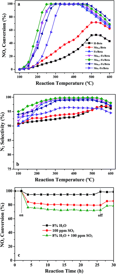
NOx reduction reactions over pure H-beta, Mo/beta, Fe/beta and Mox–Fe/beta catalysts were examined at the flow rate of 500 mL min−1 using the feeding gas containing 500 ppm NO, 500 ppm NH3 and 3% O2 in the range of 100–600 °C. It can be seen from Fig. 1a that NOx conversion changes with the increasing of reaction temperature. For H-beta, the maximum NOx conversion is only 50% in the whole temperature range. For Mo/beta catalysts, NOx conversion increases to approximately 70% at 500 °C. However, Fe/beta catalyst exhibits superior activity than Mo/beta and H-beta. With the introduction of Mo, the activity temperature window of Mox–Fe/beta catalysts at maximum NOx conversion changes. It can be seen that the temperature window of Fe/beta catalyst at maximum NOx conversion is 275–425 °C. For Mo0.2–Fe/beta catalysts, the temperature range has been enlarged to 250–475 °C. Obviously, the addition of Mo influences the activity temperature window of Mox–Fe/beta catalysts, and Mo0.2–Fe/beta catalyst exhibits the widest temperature window. Mo0.5–Fe/beta catalysts exhibit favorable high-temperature activity. Mo0.2–Fe/beta catalysts show the best low-temperature activity. Fig. 1b illustrates that the low-temperature (100–300 °C) N2 selectivity of catalysts is also influenced by the addition of Mo. When Mo loading amounts increased from 0 to 0.2% wt, the low-temperature N2 selectivity of Mox–Fe/beta catalysts increased gradually. Once Mo loadings exceed 0.2% wt, the low-temperature N2 selectivity of catalysts begins to fall. However, the high-temperature (above 425 °C) N2 selectivity of Fe/beta, Mo0.1–Fe/beta, Mo0.2–Fe/beta and Mo0.5–Fe/beta are almost unchanged. The high-temperature N2 selectivity of Mo1–Fe/beta decreases remarkably. NOx conversion begins to decrease above 425 °C due to the declining NH3 absorptivity and the unselective oxidation of NH3. These results clearly demonstrate that the appropriate amount of Mo is beneficial to improving NH3-SCR activity and broadening the temperature window.With regard to the actual use of lean SCR catalysts, sulfur and H2O are important factors that could cause the deactivation of catalysts. The effect of SO2 and H2O on the NOx conversion over Mo0.2–Fe/beta catalyst at 300 °C is displayed in Fig. 1c. The sample was continuously exposed to feeding gas containing 100 ppm SO2 and 8% H2O for 30 h, respectively. It can be seen that the initial NOx conversion is about 100% and keeps steady within 2.5 h without SO2 and H2O. When only H2O is added to the feed gas, NOx conversion decreases slightly and is maintained 95% for 20 h. The SCR activity can recover when H2O is shut off, indicating that Mo0.2–Fe/beta catalyst is not sensitive to H2O. The slight inhibiting effect is mainly attributed to the competitive adsorption of H2O and NH3 molecule on the acid sites.29,30 When only SO2 is present in the feed gas, the conversion of NOx decreases obviously, but it is still above 80% and keeps steady for 20 h. When SO2 is shut off, the SCR activity rises again, but can not reach the initial level. However, the conversion of NOx decreases severely under the coexistence of both SO2 and H2O. The reason may be the deposition of ammonium sulfate on the surface of the catalysts which can block the active sites.30,31 NOx conversion can still be maintained at approximately 75% during the reaction period. After the removal of SO2 and H2O, NOx conversion can be restored to about 80%. The above results suggest that Mo0.2–Fe/beta catalyst shows moderate resistance to sulfur and preferable H2O tolerance.
3.2 The results of XRD
XRD results (Fig. 2) exhibit that the characteristic peaks of all these samples are corresponding to beta zeolite, indicating that the original zeolite structure remains intact. In addition, no diffraction peaks corresponding to α-Fe2O3 (PDF #33-0644) and MoO3 (PDF #35-0609) crystalline phases are displayed among all catalysts, indicating that iron and molybdenum species were well dispersed on the surface of beta support as amorphous oxides. Iron and molybdenum species were well dispersed on the surface of beta support as amorphous oxides, or aggregated into minicrystals, which too small to be detected by XRD. The following SEM and TEM characterization will give particular structure information.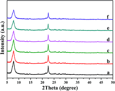 | ||
| Fig. 2 XRD patterns of pure H-beta (a); Fe/beta (b); Mo0.1–Fe/beta (c); Mo0.2–Fe/beta (d); Mo0.5–Fe/beta (e); Mo1–Fe/beta (f). | ||
3.3 The results of SEM
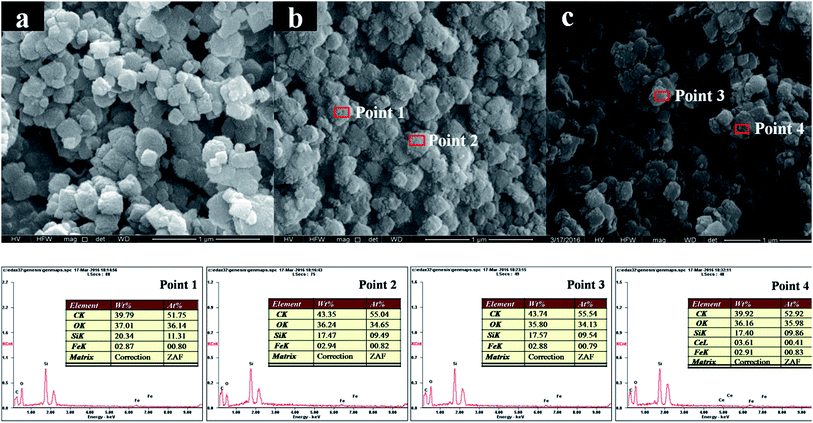
SEM was carried out to further insight into the change of the morphology induced by the loading of Mo. Fig. 3a shows SEM image of pure H-beta, which is composed of egg-like aggregates with diameter around 150 nm. No obviously change in the morphology of zeolite is observed after the incorporation of iron and molybdenum. With the introduction of Fe and Mo (Fig. 3b and c, respectively), H-beta grain surfaces are rougher by covered with a “layer”. EDX results collected from different regions (Point 1 and Point 2 in Fig. 3b; Point 3 and Point 4 in Fig. 3c) exhibit similar compositions. The average iron loadings of 2.87–2.94% wt are detected for Fe/beta and Mo0.2–Fe/beta samples (Table 1), in good agreement with the initial nominal loading amounts. Moreover, no molybdenum element is detected for the Mo0.2–Fe/beta sample. It should be due to the fact that the actual Mo loading is much lower than the detection limit. The Mo contents, determined via ICP-AES technique, are 0.07% wt, 0.12% wt, 0.43% wt and 0.87% wt in quality percentage for Mo0.1–Fe/beta, Mo0.2–Fe/beta Mo0.5–Fe/beta and Mo1–Fe/beta, respectively.3.4 The results of TEM
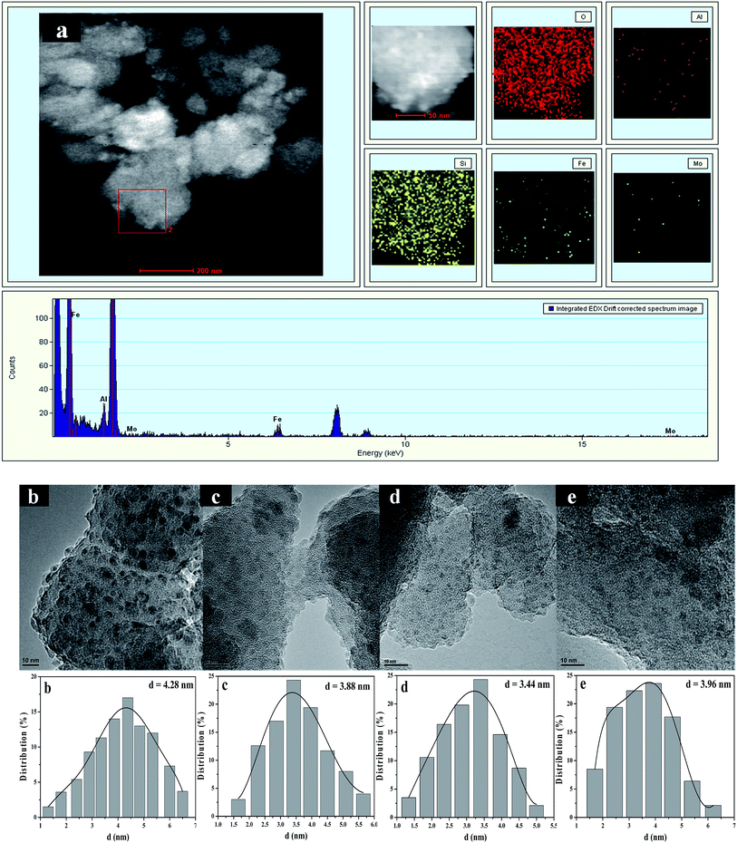
TEM images and the size distributions of supported molybdenum and iron species were further studied by HAADF-STEM characterization combining with EDS element-mapping analysis. Fig. 4a shows HAADF-STEM images of Mo0.2–Fe/beta together with the elemental mapping images for O, Al, Si, Fe and Mo in the same region. From elemental mapping image of Mo and Fe, it is clearly seen that Mo and Fe species are highly dispersed on the supports. For Fe/beta (Fig. 4b) catalyst, the faintback ground belongs to beta zeolite and the dark spots are Fe oxide nanoparticles. However, the presence of Fe oxide was not detected by XRD due to the small size of the crystallites and their high dispersion. It's noted that the average particle size for Fe oxides significantly decreased from 4.28 nm for Fe/beta to 3.44 nm for Mo0.2–Fe/beta (Fig. 4d) with the increasing of Mo loading amount. It indicates that the addition of Mo could increase the dispersion of Fe species, which played an important role in determining the extent of NOx conversion in the NH3-SCR. However, the average particle size of Fe oxide nanoparticles on Mo1–Fe/beta (3.96 nm Fig. 4e) insignificantly grew larger compared with Mo0.2–Fe/beta. It can be inferred that proper amount of Mo addition is beneficial to the dispersion of Fe species and the activity of catalysts.3.5 The results of TPD
Temperature-programmed desorption of ammonia was performed to determine the catalyst surface acidity. Fig. 5 shows NH3-TPD profiles of pure H-beta, Fe/beta and Mox–Fe/beta catalysts. A low-temperature peak (peak L) and a high temperature peak (peak H) can be observed for all samples. The former one is assigned to physically adsorbed NH3 or ammonium species adsorbed at the weak acid sites. The latter one is attributed to NH3 strongly adsorbed at the Brønsted acid sites.32 It could be seen peak L has lager area and shifts to high temperature with the addition of Fe, indicating that new Lewis acids sites form on the Fe sites. The peak H slightly shifts to higher temperature with the increasing of Mo contents from 0 to 0.5%, indicating that Brønsted acidity strengthen gradually. However, the peak H of Mo1–Fe/beta catalysts obviously shifts to low temperature. The reason is that the excess of Mo aggregates and results in the decrease of Brønsted acidity.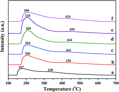 | ||
| Fig. 5 NH3-TPD curves of pure H-beta (a); Fe/beta (b); Mo0.1–Fe/beta (c); Mo0.2–Fe/beta (d); Mo0.5–Fe/beta (e); Mo1–Fe/beta (f). | ||
3.6 The results of Py-IR
Fig. 6 depicts Py-IR spectra of Fe/beta and Mox–Fe/beta catalysts after outgassing at specific temperature. In general, the typical bands from pyridine adsorption related to Lewis acid sites (L) can be observed at around 1450 cm−1, while the presence of Brønsted acid sites (B) can be seen at around 1540 cm−1.30 As shown in Fig. 6A, the bands at 1540 and 1636 cm−1 can be assigned to C–N stretching of pyridine ions to Brønsted acid sites, while the bands at 1450 and 1607 cm−1 can be assigned to the vibration of pyridine physically adsorbed to Lewis acid sites. The band at 1488 cm−1 is attributed to both B and L acid sites.30,33,34 The intensity of all the bands in Fig. 6B dramatically decreases compared with that in Fig. 6A, indicating that less NH3 can be adsorbed at high temperature than that at low temperature. The quantitative results of acid amount obtained from Py-IR measurement at 200 and 350 °C are summarized in Table 2. The amounts of Brønsted acid sites increase significantly with the introduction of Mo. Mo0.5–Fe/beta catalysts have the most abundant acid sites among all the catalysts. The excess amounts of Mo (0.1% wt) have a negative effect on the surface acid sites of the catalysts.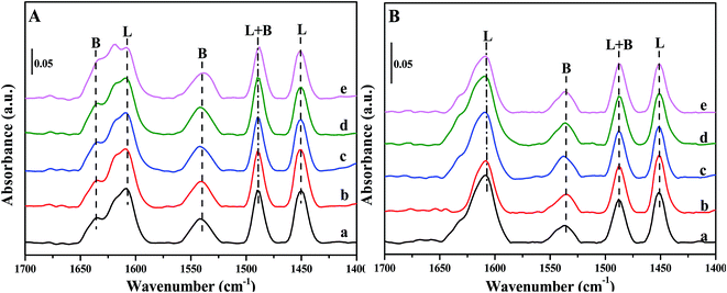 | ||
| Fig. 6 FT-IR spectra of pyridine adsorbed on Fe/beta (a); Mo0.1–Fe/beta (b); Mo0.2–Fe/beta (c); Mo0.5–Fe/beta (d); Mo1–Fe/beta (e) after degassing at 200 °C (A) and 350 °C (B). | ||
| Samples | 200 °C (μmol g−1) | 350 °C (μmol g−1) | ||
|---|---|---|---|---|
| L | B | L | B | |
| Fe/beta | 81 | 74 | 45 | 29 |
| Mo0.1–Fe/beta | 77 | 80 | 48 | 31 |
| Mo0.2–Fe/beta | 82 | 82 | 47 | 36 |
| Mo0.5–Fe/beta | 83 | 97 | 52 | 39 |
| Mo1–Fe/beta | 72 | 86 | 48 | 35 |
3.7 The results of H2-TPR
The results of H2-TPR experiments are displayed in Fig. 7. H2-TPR profile of α-Fe2O3 is also shown and there are four reduction features between 300–900 °C. The peak centered at 380 °C could be attributed to the reduction of Fe3+ to Fe2+. The peak at around 600 °C and 700 °C correspond to the reduction of Fe3O4 to FeO and FeO to Fe, respectively. The reduction peak centered at about 792 °C is ascribed to the reduction of Fe2+ to Fe0.35 A new reduction peak appeared at around 515 °C for Fe/beta and Mox–Fe/beta catalysts, which could be due to the direct reduction of Fe3O4 to Fe.36 The reduction temperature of Fe3+ species firstly decreases with the introduction of Mo (Mo0.2–Fe/beta < Mo0.1–Fe/beta < Fe/beta), which is attributed to the weakening of the Fe–O bond due to the incorporation of Mo. However, with increasing of Mo loading amounts from 0.2 to 1.0% wt, the reduction peak shifts to high temperature. This shows that the excess amount of Mo reduces the redox property of Fe species and the activity of the catalyst.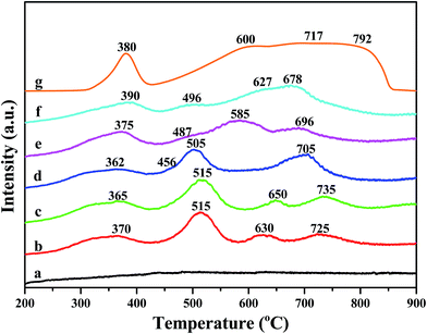 | ||
| Fig. 7 H2-TPR profiles of H-beta (a); Fe/beta (b); Mo0.1–Fe/beta (c); Mo0.2–Fe/beta (d); Mo0.5–Fe/beta (e); Mo1–Fe/beta (f); α-Fe2O3 (g). | ||
3.8 The results of XPS
XPS results of Fe 2p for Fe/beta and Mox–Fe/beta catalysts are shown in Fig. 8. Peaks located near 711.5 and 710 eV can be assigned to Fe3+ and Fe2+, respectively.12 The results from deconvolution are presented in Table 1. It is noted that Fe2+ content increases with the introduction of Mo and reaches the maximum when Mo content is 0.2% wt. With further increasing of Mo, Fe2+ content remarkably decreases. The reason can be explained that the surface of Fe2O3 is covered by a large number of MoO3, which makes it difficult to form oxygen vacancy. A more detailed explanation will be provided based on the DFT calculations in the following sections.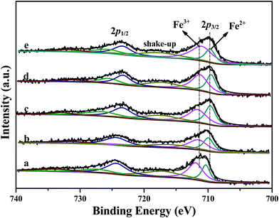 | ||
| Fig. 8 XPS results of Fe 2p of Fe/beta (a); Mo0.1–Fe/beta (b); Mo0.2–Fe/beta (c); Mo0.5–Fe/beta (d); Mo1–Fe/beta (e). | ||
3.9 The results of XANES
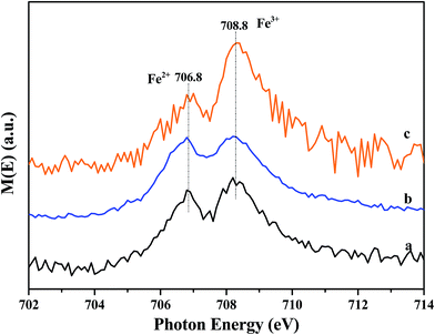
X-ray absorption near edge spectroscopy (XANES) was further performed in total electron yield mode. The samples were mixed with graphite powders to increase electric conductivity and minimize charging effect. Fe L3-edge XANES spectra of the samples are shown in Fig. 9. Two absorption peaks are observed at 706.8 eV (A1) and 708.8 eV (A2). The splitting feature of Fe L3 edge comes from the interplay of crystal field, spin-orbital and electronic interaction.37 Based on the charge transfer multiplet theory,38 the peaks at 706.8 and 708.8 eV correspond to the 2p3/2 3d electron transition for Fe2+ and Fe3+, respectively. The energy locations are consistent with the results reported by Yang.39 Furthermore, the intensity ratios of A1/(A1 + A2) for (a) Fe/beta, (b) Mo0.2–Fe/beta, (c) Mo0.5–Fe/beta are estimated to be 0.45, 0.49 and 0.38, respectively. The results show comparable quantity both Fe2+ and Fe3+ states coexist in all the samples. Specifically, Mo0.2–Fe/beta catalysts exhibit the maximum Fe2+ amounts, which is in agreement with XPS results.3.10 DFT calculations
In this work, XRD and SEM results show that the original beta zeolite structure is not destroyed with the addition of Fe and Mo. Additionally, H-beta catalysts show rather inferior activity in NH3-SCR compared with Fe/beta and Mox–Fe/beta catalysts. Therefore, it is reasonable that beta zeolite is shown to be as the support and Fe2O3 model is used to represent Fe/beta for simplicity. MoO3 is considered as the most stable existence form of Mo on the surface of Fe2O3 by our calculation. The detailed structure information is shown in Fig. S3 and Table S1,† respectively. The charge density difference plot (Fig. 10) shows that there are strong depletion of electron density around Mo atom and accumulation of electron density between Fe and O atoms, pointing to strong bonding overlap of electrons. The Bader charge we calculated shows significant electron transfer from the Fe2O3 to MoO3 species (0.28 e), which indicates that Mo can interact with the Fe species and enhance the redox ability of the surface of catalysts. The formation energy of an oxygen vacancy (Evac) by DFT calculation is +2.64 eV on the surface of MoO3/Fe2O3, and it is lower than that of pure Fe2O3 surface (Evac = 2.97 eV). The results indicate the lattice O atoms are easier to be reduced with the deposition of MoO3, in accordance with H2-TPR results. At atomic level, three O atoms of MoO3 interact with three Fe atoms of the surface of Fe2O3 and form three new bonds of Fe–O (bond length: 2.02 Å), which weaken the interaction between Fe and lattice O atom. And the lattice Fe–O bond is elongated from 1.81 Å to 1.83 or 1.84 Å with the deposition of MoO3. The formation of oxygen vacancy leads to local electrons redistribution. Analysis of calculated Bader charges shows that two Fe atoms on the surface and subsurface in vicinity of oxygen vacancy obtain 0.34 e and 0.38 e, respectively. It indicates the valence of the two Fe atoms transforms from +3 to +2. In other words, the loading of Mo species results in the increase of Fe2+ species and the decrease of the Fe3+ species, in accordance with the result of the experiment. However, with the loading amounts of Mo increase from 0.2 to 1%, the reduction peak of H2-TPR shifts to high temperature. In order to interpret aforesaid results, we carried out further theoretical calculations by increasing the number of Mo on the surface of Fe2O3. The stable (MoO3)2 and (MoO3)3 model was established and the structure was shown in Fig. S4 and S5,† respectively. The calculated Evac are 2.64 and 2.86 eV, respectively. The results indicate Evac of Fe2O3 surface increases with the increasing of MoO3. Therefore the reduction peak of Fe3+ species shifts to high temperature in H2-TPR experiment, when the loading of Mo exceed 0.2% wt.4. Discussions
With the introduction of Mo, the particle size for Fe oxides and the activity of catalysts change obviously. Mo0.2–Fe/beta catalysts exhibit the minimum particle size and favorable SCR performance. It can be concluded that Mo plays an important role in influencing the particle size of iron species and the catalytic performance, which is consistent with previous report.40 In bimetallic catalysts, the introduction of a second metal is found to suppress the aggregation of monometals.41 In this work, the smaller iron oxides can exist stably due to the anchor of Mo6+ on the iron phase, and then disperse well on the zeolite. However, the average particle size of Fe oxides becomes bigger with the further increasing of Mo loading amounts. It could be due to the formation of crystalline Mo oxides,42 which fail to disperse Fe species and reduce the activity of catalysts.NH3-TPD and Py-IR result show that the strength of Brønsted acidity enhance with an increase of Mo loading. Brønsted acid sites are considered to be associated with Mo–OH groups41,43 except that on the beta zeolite. However, Brønsted acidity begins to decrease when Mo loading amounts is above 0.5% wt. An obvious variation of Brønsted acidity can be observed: Mo0.5–Fe/beta > Mo0.2–Fe/beta > Mo0.1–Fe/beta > Mo1–Fe/beta > Fe/beta. The order is in line with that of high-temperature activity. The strong Brønsted acidity results in excellent NH3 adsorption ability, which is beneficial to improving the high-temperature SCR performance.44 However, no relation between low-temperature activity and Brønsted acidity is observed. At low temperature more acid sites exist on the surface of catalysts than that at the high temperature. Enough NH3 can be absorbed and reacts with NOx to N2. NH3 adsorption is not a crucial factor for low-temperature SCR performance. On the other hand, less acid Brønsted acid sites exist on the surface of catalyst at high temperature, indicating that less absorbed NH3 can participate in NH3-SCR reaction. Moreover, the part of absorbed NH3 would also be oxidized to NOx or decomposed to N2 at high temperature.45 Therefore, NH3 adsorption becomes a rate-limiting step and Brønsted acid sites are responsible for high-temperature activity. Mo0.5–Fe/beta exhibits the best high-temperature activity, which is attributed to the highest Brønsted acidity.
Based on H2-TPR results, Fe3+ species are easily reduced to Fe2+ when Mo loading amounts reach 0.2% wt, and more oxygen vacancies form on the surface of catalysts simultaneously. This indicates the incorporation of Mo enhances redox property of catalysts. With the further increasing of Mo, the reduction peak of Fe3+ species shifts to high temperature. There should be less Fe2+ species for Mo0.5–Fe/beta and Mo1Fe/beta catalysts. This is in accordance with the results of XPS and XANES. On the other hand, Mo0.2–Fe/beta catalysts possess maximum Fe2+ content. Compared with the low-temperature activity in Fig. 1, a similar variation trend can be observed: Mo0.2–Fe/beta > Mo0.1–Fe/beta > Fe/beta > Mo0.5–Fe/beta > Mo1Fe/beta. It is apparent that superior low-temperature activity is mainly attributed to the higher Fe2+ content. Accompanied by the addition of Mo, Fe3+ species translate into Fe2+ in the vicinity of oxygen vacancy due to the transition of electron. O2 are adsorbed on the oxygen vacancy and form active chemisorbed oxygen. Chemisorbed oxygen has been considered to be the most active oxygen species and to play an important role in the redox reaction.30 As for low-temperature NH3-SCR reaction, the chemisorbed oxygen more easily binds with NO molecule than lattice oxygen to form NO2.46 NO oxidation is considered as one of the key reactions in the standard SCR and has been proposed to be the rate determining step in the literature.47–50 The formed NO2 species then react with adsorbed NH3 species on the adjacent Brønsted acid sites to form NH4NO3,51 which further decomposes to N2 and H2O. A Langmuir–Hinshelwood mechanism,52 which considers the NH3 adsorption on acidic sites and the NO oxidation on Fe sites, is proposed. Therefore, high concentrations of chemisorbed oxygen is beneficial for NOx reduction due to an increased rate of NO to NO2 oxidation.53 Mo0.2–Fe/beta catalyst exhibits the best low-temperature performance for the increased oxygen vacancy, which is caused by the introduction of Mo.
5. Conclusions
Mo0.2–Fe/beta catalysts exhibit the widest activity temperature window (225–525 °C) at NOx conversion above 90%. Moreover, Mo0.2–Fe/beta catalyst shows moderate resistance to sulfur and preferable H2O tolerance.The introduction of Mo can change the amounts of Brønsted acid sites, which may improve the high-temperature performance of Fe/beta catalysts. NH3-TPD and Py-IR results demonstrate that Brønsted acidity of catalyst surface changes obviously with the increasing of Mo loading amounts.
The addition of Mo influences the dispersion of iron species, and Mo0.2–Fe/beta exhibits the minimum average size of Fe oxide particles.
The introduction of Mo has a significant influence on Fe2+ content, which is verified by the results of XPS and XANES. The structure of catalyst surface changes due to the interaction of Fe and Mo. More oxygen vacancies and Fe2+ are produced on the surface of catalysts, which is beneficial to the low-temperature SCR activity. DFT calculations further illuminate the change of oxygen vacancy formation energy, Fe2+ contents and electronic properties.
Acknowledgements
This work was financially supported by the National Natural Science Foundation of China (21673290, 21376261 and 21503273) and 863 Program of China (2015AA034603). The XANES experiments at Spring-8 were, performed on the BL27SU Beamline with the approval of the Japan Synchrotron Radiation Research Institute (JASRI) (Proposal No. 2016A1039).References
- S. Brandenberger, O. Kröcher, A. Tissler and R. Althoff, Catal. Rev., 2008, 50, 492–531 CAS.
- P. Granger and V. Parvulescu, Chem. Rev., 2011, 111, 3155–3207 CrossRef CAS PubMed.
- J. Li, R. Zhu, Y. Cheng, C. K. Lambert and R. T. Yang, Environ. Sci. Technol., 2010, 44, 1799–1805 CrossRef CAS PubMed.
- A. M. Beale, F. Gao, I. Lezcano-Gonzalez, C. H. F. Peden and J. Szanyi, Chem. Soc. Rev., 2015, 44, 7371–7405 RSC.
- J. Dědeček, L. Čapek, P. Sazama, Z. Sobalík and B. Wichterlová, Appl. Catal., A, 2011, 391, 244–253 CrossRef.
- X. Zhang, Q. Shen, C. He, C. Ma, J. Cheng, L. Li and Z. Hao, ACS Catal., 2012, 2, 512–520 CrossRef CAS.
- P. Chen, D. Rauch, P. Weide, S. Schönebaum, T. Simons, M. Muhler, R. Moos and U. Simon, Appl. Catal., B, 2014, 148, 520–531 Search PubMed.
- A. J. O'Malley, I. Hitchcock, M. Sarwar, I. P. Silverwood, S. Hindocha, C. R. A. Catlow, A. P. E. York and P. J. Collier, Phys. Chem. Chem. Phys., 2003, 5, 3328–3333 RSC.
- N. Liu, R. Zhang, B. Chen, Y. Li and Y. Li, J. Catal., 2012, 294, 99–112 CrossRef CAS.
- F. Liu, K. Asakura, H. He, Y. Liu, W. Shan, X. Shi and C. Zhang, Catal. Today, 2011, 164, 520–527 CrossRef CAS.
- S. Shwan, R. Nedyalkova, J. Jansson, J. Korsgren, L. Olsson and M. Skoglundh, Ind. Eng. Chem. Res., 2012, 51, 12762–12772 CrossRef CAS.
- C. He, Y. Wang, Y. Cheng, C. K. Lambert and R. T. Yang, Appl. Catal., B, 2009, 368, 121–126 CrossRef CAS.
- R. Nedyalkova, S. Shwan, M. Skoglundh and L. Olsson, Appl. Catal., B, 2013, 138–139, 373–380 CrossRef CAS.
- R. Q. Long and R. T. Yang, J. Catal., 2002, 207, 224–231 CrossRef CAS.
- M. Devadas, O. Krocher, M. Elsener, A. Wokaun, G. Mitrikas, N. Soger, M. Pfeifer, Y. Demel and L. Mussann, Catal. Today, 2007, 119, 137–144 CrossRef CAS.
- F. Liu, H. He, Z. Lian, W. Shan, L. Xie, K. Asakura, W. Yang and H. Deng, J. Catal., 2013, 307, 340–351 CrossRef CAS.
- M. Kobayashi and K. Miyoshi, Appl. Catal., B, 2007, 7, 253–261 CrossRef.
- Z. Liu, S. Zhang, J. Li and L. Ma, Appl. Catal., B, 2014, 144, 90–95 CrossRef CAS.
- S. Ding, F. Liu, X. Shi, K. Liu, Z. Lian, L. Xie and H. He, ACS Appl. Mater. Interfaces, 2015, 7, 9497–9506 CAS.
- J. P. Perdew, K. Burke and M. Ernzerhof, Phys. Rev. Lett., 1996, 77, 3865–3868 CrossRef CAS PubMed.
- M. Fuchs and M. Scheffler, Comput. Phys. Commun., 1999, 119, 67–98 CrossRef CAS.
- P. E. Blöchl, Phys. Rev. B: Condens. Matter Mater. Phys., 1994, 50, 17953–17979 CrossRef.
- A. J. Cohen, P. Mori-Sánchez and W. Yang, Science, 2008, 321, 792–794 CrossRef CAS PubMed.
- X. Huang, S. K. Ramadugu and S. E. Mason, J. Phys. Chem. C, 2016, 120, 4919–4930 CAS.
- M. Lübbe and W. Moritz, J. Phys.: Condens. Matter, 2009, 21, 134010 CrossRef PubMed.
- E. Wasserman, J. R. Rustad, A. R. Felmy, B. P. Hay and J. W. Halley, Surf. Sci., 1997, 385, 217–239 CrossRef CAS.
- S. Thevuthasan, Y. J. Kim, S. I. Yi, S. A. Chambers, J. Morais, R. Denecke, C. S. Fadley, P. Liu, T. Kendelewicz and G. E. Brown, Surf. Sci., 1999, 425, 276–286 CrossRef CAS.
- L. M. Sandratskii, M. Uhl and J. Kübler, J. Phys.: Condens. Matter, 1995, 8, 983–989 CrossRef.
- G. Busca, L. Lietti, G. Ramis and F. Berti, Appl. Catal., B, 1998, 18, 1–36 CrossRef CAS.
- T. Zhang, R. Qu, W. Su and J. Li, Appl. Catal., B, 2015, 176–177, 338–346 CrossRef CAS.
- K. Wijayanti, K. Leistner, S. Chand, A. Kumar, K. Kamasamudram, N. W. Currier, A. Yezerets and L. Olsson, Catal. Sci. Technol., 2016, 6, 2565–2579 CAS.
- K. Jisa, J. Novakova, M. Schwarze, A. Vondrova, S. Sklenak and Z. Sobalik, J. Catal., 2009, 262, 27–34 CrossRef CAS.
- M. Tamura, K. Shimizu and A. Satsuma, Appl. Catal., A, 2012, 433–434, 135–145 CrossRef CAS.
- C. R. Reddy, Y. S. Bhat, G. Nagendrappa and B. S. Jai Prakash, Catal. Today, 2009, 141, 157–160 CrossRef CAS.
- G. Delahay, D. Valade, A. Guzmán-Vagas and B. Coq, Appl. Catal., B, 2005, 55, 149–155 CrossRef CAS.
- M. Mauvezin, G. Delahay, B. Coq, S. Kieger, J. C. Jumas and J. Olivier-Fourcade, J. Phys. Chem. B, 2001, 105, 928–935 CrossRef CAS.
- P. S. Miedema and F. M. F. De Groot, J. Electron Spectrosc. Relat. Phenom., 2013, 187, 32–48 CrossRef CAS.
- F. M. De Groot, Coord. Chem. Rev., 2005, 249, 31–63 CrossRef CAS.
- S. Yang, D. Wang, G. Liang, Y. M. Yiu, J. Wang, L. Liu, X. Sun and T. Sham, Energy Environ. Sci., 2012, 5, 7007–7016 CAS.
- T. Gu, R. Jin, Y. Liu, H. Liu, X. Weng and Z. Wu, Appl. Catal., B, 2013, 129, 30–38 CrossRef CAS.
- C. L. Bracey, P. R. Ellis and G. J. Hutchings, Chem. Soc. Rev., 2009, 38, 2231–2243 RSC.
- L. Lietti, I. Nova, G. Ramis, L. Dall'Acqua, G. Busca, E. Giamello, P. Forzatti and F. Bregani, J. Catal., 1999, 187, 419–435 CrossRef CAS.
- X. Li and Y. Li, J. Mol. Catal. A: Chem., 2014, 386, 69–77 CrossRef CAS.
- S. Brandenberger, O. Kroecher, A. Wokaun, A. Tissler and R. Althoff, J. Catal., 2009, 268, 297–306 CrossRef CAS.
- R. M. Heck, J. M. Chen and B. K. Speronello, Environ. Prog. Sustainable Energy, 1994, 13, 221–225 CAS.
- P. Maitarad, J. Han, D. Zhang, L. Shi, S. Namuangruk and T. Rungrotmongkol, J. Phys. Chem. C, 2014, 118, 9612–9620 CAS.
- M. Devadas, O. Krocher, M. Elsener, A. Wokaun, N. Soger, M. Pfeifer, Y. Demel and L. Mussmann, Appl. Catal., B, 2006, 67, 187–196 CrossRef CAS.
- J. Eng and C. H. Bartholomew, J. Catal., 1997, 171, 14–26 CrossRef CAS.
- M. Wallin, C. J. Karlsson, M. Skoglundh and A. Palmqvist, J. Catal., 2003, 218, 354–364 CrossRef CAS.
- M. Iwasaki, K. Yamazaki and H. Shinjoh, Appl. Catal., A, 2009, 366, 84–92 CrossRef CAS.
- R. Q. Long and R. T. Yang, J. Catal., 2002, 207, 274–285 CrossRef CAS.
- P. S. Metkar, N. Salazar, R. Muncrief, V. Balakotaiah and M. P. Harold, Appl. Catal., B, 2011, 104, 110–126 CrossRef CAS.
- Z. Wu, R. Jin, Y. Liu and H. Wang, Catal. Commun., 2008, 9, 2217–2220 CrossRef CAS.
Footnotes |
| † Electronic supplementary information (ESI) available. See DOI: 10.1039/c6ra27126j |
| ‡ These authors contributed equally as the first author. |
| This journal is © The Royal Society of Chemistry 2017 |

