
 Open Access Article
 This Open Access Article is licensed under a Creative Commons Attribution-Non Commercial 3.0 Unported Licence
Formation mechanism and properties of fluoride–phosphate conversion coating on titanium alloy
Shuaixing Wang *a,
Xiaohui Liua,
Liqiang Wangb,
Qingjie Wenb,
Nan Dua and
Jianhang Huanga
*a,
Xiaohui Liua,
Liqiang Wangb,
Qingjie Wenb,
Nan Dua and
Jianhang Huanga
aNational Defense Key Discipline Laboratory of Light Alloy Processing Science and Technology, Nanchang Hangkong University, Nanchang 330063, P. R. China. E-mail: wsxxpg@126.com
bAVIC Chengdu Aircraft Industrial (Group) Co., Ltd., Chengdu 610091, P. R. China
First published on 13th March 2017
Abstract
A uniform grey conversion coating with the thickness of 4–5 μm was prepared on titanium alloy by a fluoride–phosphate treatment. Scratch testing results indicated that the conversion coating greatly improved the adhesion strength of the paint coat to the titanium substrate. The growth mechanism of the conversion coating was analyzed comprehensively by E–t curve, SEM, EDS, XPS and XRD. In the conversion process, the titanium substrate was first dissolved (0–45 s), then Na3TiF6 nucleation occurred via a series of reactions (45–120 s), whereby the conversion coating grew steadily with the nucleation and growth of Na3TiF6 grains (120–600 s); after 600 s, the conversion coating reached dynamic equilibrium of growth/dissolution. In the drying process at 100 ± 5 °C, some Na3TiF6 grains reacted with O2 to form Na3TiOF5. The components of the conversion coating were Na3TiF6, Na3TiOF5, a little TiO2, TiF4 and phosphate derivatives.
1. Introduction
Titanium and its alloys are increasingly applied in the aerospace industry, such as in airframes, engine components, fasteners and others, owing to their excellent combination of low density, high strength-to-weight ratio and good corrosion resistance.1,2 However, drawbacks, such as low surface hardness, high friction coefficient and poor adhesion with organic coatings, limit the direct application of titanium alloys. A variety of surface treatment technologies, including anodizing, micro-arc oxidation, chemical conversion, surface alloying and physical vapour deposition, have been employed to improve the surface performance of titanium alloys.3 Amongst the mentioned surface treatment technologies, chemical conversion coating is the primary surface pretreatment for titanium alloy in the aerospace industry, and it provides good corrosion protection, promotes the adhesion with paints and has a low processing cost.4,5 However, an excellent coating is difficult to convert on titanium using the traditional chemical conversion technology based on chromates and phosphates,6–8 due to the presence of the passive oxide film. Therefore, zinc phosphating,9 trivalent chromium-phosphated conversion10,11 and fluoride–phosphate conversion coating12 are gradually being developed in line with the existing and emerging requirements. Besides, the eco-friendly pretreatment techniques for aluminium alloy, including rare-earth conversion,13,14 molybdate conversion,15 silane treatment,16 phytic acid (PA) treatment17 and Zr/Ti-based treatment18–20 may also be used for the pretreatment of titanium alloy. In general, the fluoride–phosphate conversion technique is the most effective pretreatment system for titanium alloy, and has even been adopted as an official aerospace material specification (AMS 2486D).12 However, so far there has been no report about the chemical composition, microstructure and formation mechanism of the fluoride–phosphate conversion coating on titanium alloy.In many case, the precipitation of these ultra-thin conversion coatings is an electrochemically driven process and requires the dissolution of alloy and a subsequent film deposition.5,17,20–24 The literature20,21 reports that the formation of a Ti/Zr-based conversion coating on aluminium alloy can be deemed as a nucleation, followed by the growth of Na3AlF6 crystal and formation of a metal–organic complex. In the formation process of a zinc phosphate (ZPO) layer on aluminium, ZPO crystals primarily occur on and around the intermetallic particles.22 Zhao9 indicated that ZPO conversion coating on pure titanium experiences a similar nucleation step, and that ultrasonic irradiation can improve the nucleation and growth of ZPO. Besides, Li17 found that PA induced the effective deposition of reaction products and the formation of the conversion coating in a mixed conversion system of PA and NH4F for Ti-6Al-4V alloy. Although the formation of a fluoride–phosphate conversion coating on titanium alloy may undergo similar processes, the basic theories about the coating composition and the coating–forming reactions are not yet clear, until now.
The aim of the present work was to gain an insight into the deposition mechanism of a fluoride–phosphate conversion coating on titanium alloy. For this purpose, the open circuit potential (OCP) of titanium alloy in a conversion bath was completely monitored. The transformation of the morphology and the chemical composition of the coating during the conversion process were analyzed by SEM and EDS. In addition, X-ray photoelectron spectroscopy (XPS) and X-ray diffraction (XRD) were used to accurately determine the chemical composition of the conversion coating. Moreover, the corrosion resistance and the paint adhesion of the conversion coating were evaluated by electrochemical impedance spectroscopy (EIS) and scratch testing, respectively. A possible formation mechanism for a fluoride–phosphate conversion coating on TC1 alloy is proposed.
2. Experimental
2.1 Materials
TC1 panels of 2.0 mm thickness were supplied by Baoti Corp., China. The main chemical composition of the TC1 alloy was 1.0–2.5 wt% Al, 0.7–2.0 wt% Mn, 0.30 wt% Si, and bal. Al. The specimens with a dimension of 25 mm × 20 mm were cut from the panels, polished with abrasive papers, ultrasonically cleaned in ethanol and finally dried in warm air.2.2 Preparation of conversion coating
Prior to chemical conversion treatment, the samples were sequentially treated by the following steps: degreasing in an aqueous solution containing 30 g L−1 Na2CO3, 20 g L−1 Na3PO4 and 5 g L−1 Na2SiO3 at 60 °C for 2 min, rinsing in deionised water, pickling in 20 vol% HNO3 solution at room temperature for 1 min and finally rinsing with deionised water.The cleaned samples were immediately immersed in a fluoride–phosphate conversion solution at 30 ± 3 °C for different times. The conversion bath consisted of 40 g L−1 Na3PO4, 15 g L−1 NaF and 25 mL L−1 HAc. The pH of the conversion baths was adjusted to 4.0–5.0 by adding HF or NaOH solution. After the surface treatment, the samples were rinsed thoroughly with deionised water, and then dried in warm air or at 100 ± 5 °C for 30 min.
2.3 Electrochemical tests
Electrochemical tests were conducted by using an Autolab PGSTAT 302N. The tests were performed by using a three-electrode electrochemical cell. A saturated calomel electrode (SCE) and a platinum sheet were used as the reference and counter electrodes, respectively. The titanium specimens were coated with epoxy resin, with an area of 1 cm2 left exposed for the electrochemical testing. E–t curves of the TC1 samples in the conversion bath were acquired for 20 min, with a step of 1 s. EIS values of the samples in 3.5 wt% NaCl solution were acquired at the OCP over the frequency range of 105 to 10−2 Hz using an AC signal amplitude of 10 mV. Prior to testing, the samples were immersed for ∼0.5 h in a NaCl solution in order to stabilize the OCP. The equivalent circuits were fitted using the Zsimpwin software. All the experiments were repeated with three duplicate specimens to confirm the reproducibility of the results, and the typical result or the average of the three measurements is reported in this paper.2.4 Characterization
The surface morphology and cross-sectional morphology of the conversion coating were analyzed by field emission gun SEM (FE-SEM, Nova Nano-SEM 450). Cross-sections of the specimens were ground by successive grades of SiC paper, followed by finishing with a 1 μm diamond. The chemical compositions were examined by energy dispersive X-ray spectroscopy (EDS, INCA 250). Phase compositions were investigated by X-ray diffraction analysis (XRD) using a Bruker D8 ADVANCE instrument equipped with Cu Kα. The intensity data were collected in a 2θ range from 10° to 70° with a scan rate of 0.02° s−1. X-ray photoelectron spectroscopy (XPS) measurements were conducted in an Axis Ultra DLD equipped with a standard Al Kα X-ray source (1486.6 eV) and a hemispherical analyzer.2.5 Paint adhesion
TC1 samples without and with chemical treatments were painted with S06-1010H polyurethane primer (Tianjin Lighthouse Coating Co., Ltd., China). The thickness of the paint coat was about 30–35 μm. The adhesion of the polyurethane coating to the substrates was determined by a single scratch tester (WS-2005, Lanzhou Institute of Chemical Physics, CAS, China). The measurements were done before (dry adhesion) and after (wet adhesion) 7 days of the paint-coated samples exposure to 3.5 wt% NaCl solution. During the scratch testing, acoustic emission (AE) signals were measured with a diamond indenter (120° cone with a 200 μm radius tip) under a loading rate of 40 N min−1, loading range of 0–80 N and scratch length of 6 mm. During the scratch testing, the load at which the coating was removed from the substrate was designated as the critical load (LC) and the moment was recorded by an acoustic emission (AE) signal.25 The profiles of the scratched coating were measured using a KH-7700 3D video microscope.3. Results and discussion
3.1 Coating growth curve
Fig. 1 shows the variation curves of the OCP and the coating weight in the fluoride–phosphate conversion process. It was found that the OCP decreased sharply before 45 s, and then greatly increased at 45–600 s and then became stabile after 600 s. The coating weight had a similar variation law with the OCP at 120–900 s. The coating weight increased sharply at 120–420 s, increased slightly at 420–600 s, but tended to be stable at 600–900 s. According to the variation of the OCP and coating weight, the growth process for the conversion coating can be divided into four stages: dissolution of the substrate (0–45 s), rapid growth of the coating (45–420 s), slow growth of the coating (420–600 s) and the dynamic equilibrium of the coating growth/dissolution (>600 s). | ||
| Fig. 1 E–t curve in the conversion process and growth curve of the fluoride–phosphate conversion coating. | ||
The fluoride–phosphate conversion bath was made mildly acidic by adjusting the pH in the range of 4.0–5.0. When the sample was immersed in the conversion bath, the titanium substrate was immediately dissolved to Ti4+. In this stage (0–45 s), the OCP decreased sharply, accompanied with hydrogen evolution. With the increasing of Ti4+ on the interface of the electrode/solution, nucleation was formed on the partial sites of the bare substrate via stepwise reactions, at which point, the grains continuously nucleated and grew to form the primary conversion coating. Therefore, the coating grew rapidly, and the OCP increased greatly at 45–420 s. With the thickening of the coating, the dissolution of the titanium substrate and the diffusion of Ti4+ became difficult, and the growth of grains became inhibited. However, a little Ti4+ could be still formed from micro-dissolution of the conversion bath on the primary coating, and so the nucleation reactions still occurred at the coating/solution interface. So the conversion coating still grew slowly in this stage (420–600 s). Meanwhile, the OCP increased slightly. After 600 s, the dissolving of the coating was aggravated, and the conversion process entered the dynamic stage of coating growth/dissolution, and thus the coating did not grow and the OCP stabilized.
3.2 Coating morphologies
Fig. 2a–e give the surface morphologies of the fluoride–phosphate conversion coating formed at different times. As shown in Fig. 2a, grains formed on the partial sites of the TC1 surface when the sample was immersed in the conversion bath for 2 min, but most regions were in the activated state. As the conversion time was extended, the nucleation sites increased and the grains gradually grew. There were many larger grains on the electrode surface at 4 min, as shown in Fig. 2b. When the conversion time was 6 min, the grains nearly covered all of the surface to form the primary conversion coating. Besides this, the nucleation reaction can also occur at the interface of the coating/solution, and secondary grains could be formed on the coating surface, as shown in Fig. 2c. A complete and uniform conversion coating could be found after 10 min (Fig. 2d and e). Meanwhile, the secondary grains appeared on the surface with the complete coating.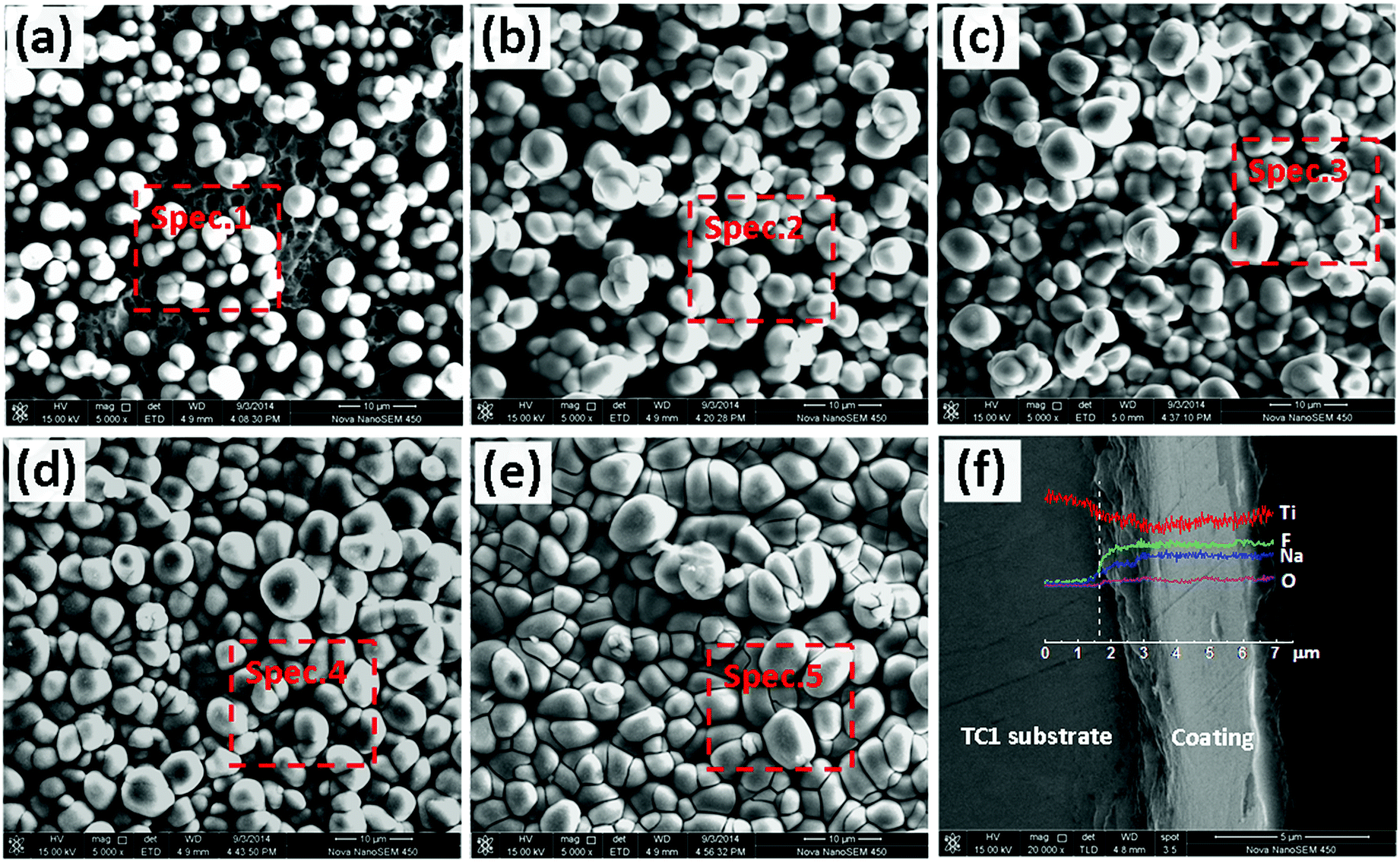 | ||
| Fig. 2 Surface SEM images of the fluoride–phosphate conversion coating formed at: 2 min (a), 4 min (b), 6 min (c), 10 min (d) and 15 min (e). Cross-section SEM image and EDS spectrum of the conversion coating formed at 10 min (f). | ||
Fig. 2f shows the cross-sectional morphology and elemental distribution of the fluoride–phosphate conversion coating formed at 10 min. As shown in Fig. 2f, the conversion coating was about 4–5 μm thickness, uniform and it closely adhered to the substrate, suggesting a high interface bonding strength. Besides, the conversion coating exhibited a tendency of outgrowth. From the coating/substrate interface to the coating surface, Ti element showed a decreasing trend, while F and Na elements increased gradually to a stable content within ∼3 μm of the substrate.
3.3 Coating composition
Table 1 gives the element information of the different conversion coatings marked in Fig. 2. As shown in Table 1, all the coatings had Ti, F, Na, O and a little P. Besides, while the Ti content decreased, the F and Na contents ascended and the O content was maintained at about 5 wt% with the increase in conversion time. It could be confirmed that Ti mainly came from the TC1 substrate. The high levels of F and Na suggested the conversion bath was involved in the coating–forming reactions. Moreover, the changes of Ti, F and Na could illustrate the growth process of the coating. As the conversion time increased, the coating thickened and Ti4+ formed by dissolution of the substrate could not be effectively diffused into the coating surface, but the coating–forming reactions still occurred, relying on there being a little Ti4+ formed by the micro-dissolution of the primary coating, which resulted in a decrease in the Ti content and an increase in the F and Na contents. Interestingly, the variation of F and Na in Table 2 is consistent with the variation in Fig. 2f. Both Table 2 and Fig. 2f confirmed that the growth of the conversion coating mainly depended on the reaction of the conversion bath with Ti4+ formed by dissolution of the primary coating in the later stage of film-forming.| Coating | Location | Elements (wt%) | |||||
|---|---|---|---|---|---|---|---|
| Ti | O | F | Na | P | Al | ||
| 2 min | Spec.1 | 35.66 | 5.91 | 44.63 | 12.29 | 0.53 | 0.37 |
| 4 min | Spec.2 | 24.18 | 5.77 | 51.54 | 17.43 | 0.75 | — |
| 6 min | Spec.3 | 21.67 | 5.89 | 52.62 | 18.97 | 0.85 | — |
| 10 min | Spec.4 | 16.54 | 5.22 | 54.83 | 22.34 | 1.07 | — |
| 15 min | Spec.5 | 17.00 | 5.64 | 54.12 | 22.11 | 1.13 | — |
| Sample | Rf/Ω cm2 | CPEf | Rct/Ω cm2 | Cdl/F cm−2 | |
|---|---|---|---|---|---|
| Y0/Ω−1 cm−2 s−n | nf | ||||
| Uncoated | 1.146 × 10⁴ | 6.024 × 10⁻⁵ | 0.6291 | 82.16 | 4.445 × 10⁻⁵ |
| Coating (4 min) | 1.630 × 10⁴ | 2.380 × 10⁻⁴ | 0.7986 | 314.3 | 1.210 × 10⁻⁶ |
| Coating (8 min) | 2.535 × 10⁴ | 1.673 × 10⁻⁴ | 0.7818 | 359.9 | 3.429 × 10⁻⁷ |
| Coating (10 min) | 4.373 × 10⁴ | 1.161 × 10⁻⁴ | 0.9341 | 422.5 | 3.776 × 10⁻⁷ |
| Coating (15 min) | 4.293 × 10⁴ | 4.112 × 10⁻⁵ | 0.8329 | 363.7 | 2.816 × 10⁻⁷ |
XRD patterns of the bare TC1 alloy and various fluoride–phosphate conversion coatings are illustrated in Fig. 3. It can be seen that there were obvious differences in the XRD patterns between bare and coated TC1 alloy. For the bare TC1 alloy (Fig. 3a), only Ti peaks were characterized, since the self-formed oxide film was too thin to be reflected by XRD. The peaks of Na3TiF6 were detected in the conversion coating just formed after 4 min. With the extension in the film-forming time, numerous Na3TiF6 and a few rutile-TiO2 were present in the coating formed at 10 min (Fig. 3c). Besides, as shown in Fig. 3d, many strong diffraction peaks attributed to Na3TiOF5 were also identified in the coating after drying at 100 °C for 30 min. This phenomenon indicated that some Na3TiF6 may react with O2 to form Na3TiOF5 in the drying process.26
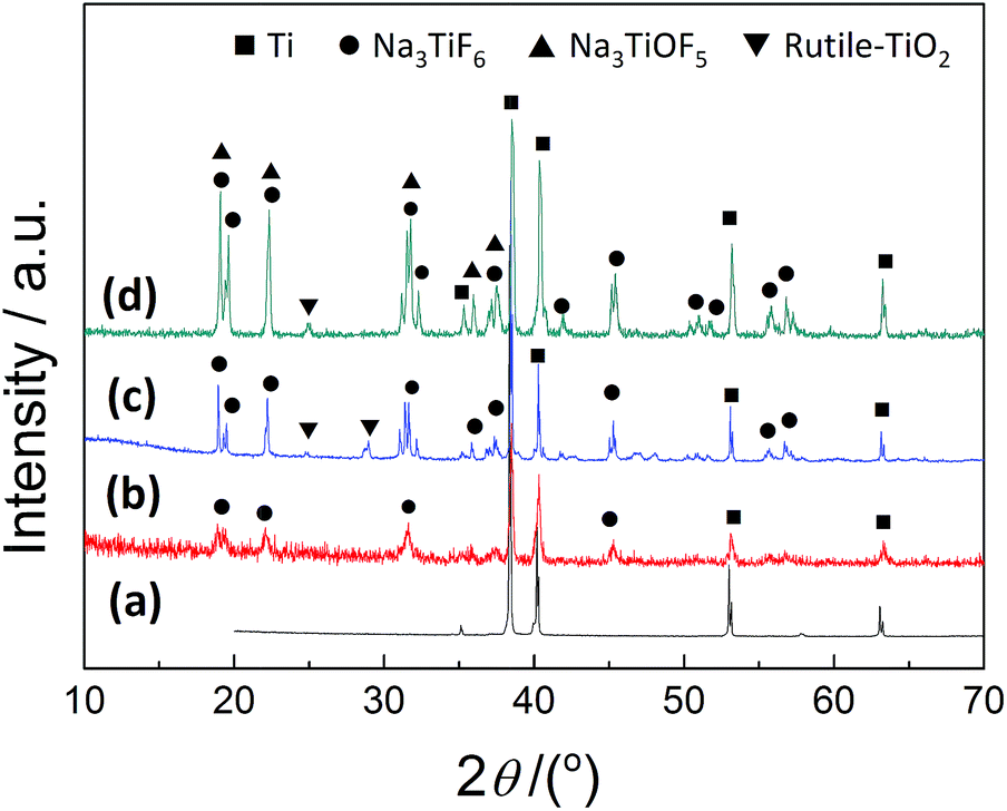 | ||
| Fig. 3 XRD patterns of bare TC1 alloy (a) and fluoride–phosphate conversion coatings formed at: 4 min (b), 10 min (c) and coating with drying at 100 °C for 30 min (d). | ||
Moreover, Fig. 4a presents the XPS survey spectra of the bare TC1 alloy and the fluoride–phosphate conversion coating formed at 10 min. The details of the peaks of Ti 2p, O 1s, F 1s, Na 1s and P 2p are shown in Fig. 4b–f, respectively. The survey spectra (Fig. 4a) indicate the presence of Ti, O and Al at the TC1 surface. According to the binding energy of Ti 2p and O 1s, it can be determined that both pure-Ti, TiO2 and a few Al2O3 exist on the surface of the TC1 alloy.
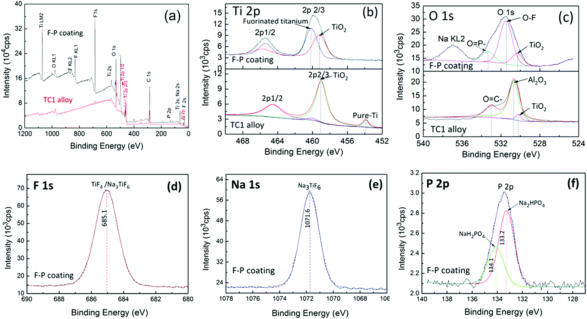 | ||
| Fig. 4 XPS spectra (a), Ti 2p (b), O 1s (c), F 1s (c), Na 1s (d) and P 2p (e) and XRD spectrum (f) of bare TC1 alloy and the fluoride–phosphate conversion coating formed at 10 min. | ||
However, Ti, F, O, Na and P were detected on the coating surface, which is basically consistent with the EDS results. As shown in Fig. 4b, the Ti 2p3/2 core-level spectrum could be curve-fitted into two peak with binding energies at about 459.2 eV and 460.1 eV, which were assigned to TiO2 (ref. 27) and fluorinated titanium,27,28 respectively. The O 1s spectrum (Fig. 4c) consists of three peaks. The main peak at 531.5 eV might be associated with oxygen bound to multiple fluorine atoms (O–F).29 The other peaks at 530.1 eV and 533.3 eV were attributed to TiO2 and O![[double bond, length as m-dash]](https://www.rsc.org/images/entities/char_e001.gif) P–, respectively. The binding energy of F 1s (Fig. 4d) was about 685.1 eV, which represented TiF4 or Na3TiF6.28–30 The only peak of Na 1s (Fig. 4e) at 1071.6 eV also corresponded to Na3TiF6. Besides, the O 1s peak at 533.3 eV and the P 2p peaks (Fig. 4f) showed the presence of Na2HPO4 and NaH2PO4,31,32 which suggested that the disproportionation of phosphate might occur in the conversion process.
P–, respectively. The binding energy of F 1s (Fig. 4d) was about 685.1 eV, which represented TiF4 or Na3TiF6.28–30 The only peak of Na 1s (Fig. 4e) at 1071.6 eV also corresponded to Na3TiF6. Besides, the O 1s peak at 533.3 eV and the P 2p peaks (Fig. 4f) showed the presence of Na2HPO4 and NaH2PO4,31,32 which suggested that the disproportionation of phosphate might occur in the conversion process.
The comprehensive results of XPS and XRD illustrated that the chemical components of the fluoride–phosphate conversion coating were Na3TiF6, Na3TiOF5, a little TiO2, TiF4 and phosphate derivatives.
3.4 Discussion of the formation mechanism
The E–t curve (Fig. 1), surface morphologies (Fig. 2a–e) and cross-sectional morphology (Fig. 2f) of the conversion coating sufficiently showed that the growth process of the conversion coating was divided into four stages: substrate dissolving (0–45 s); initial nucleation (45–120 s); coating growth (120–600 s, including rapid and slow growth) and the dynamic equilibrium of coating growth/dissolution (>600 s). The EDS (Table 1), XRD (Fig. 3) and XPS (Fig. 4) analysis results revealed that the composition of the conversion coating was Na3TiF6, Na3TiOF5, a few TiO2, TiF4 and phosphate derivatives. Based on previously discussed results, a deposition mechanism of the fluoride–phosphate conversion coating is proposed, and is schematically presented in Fig. 5.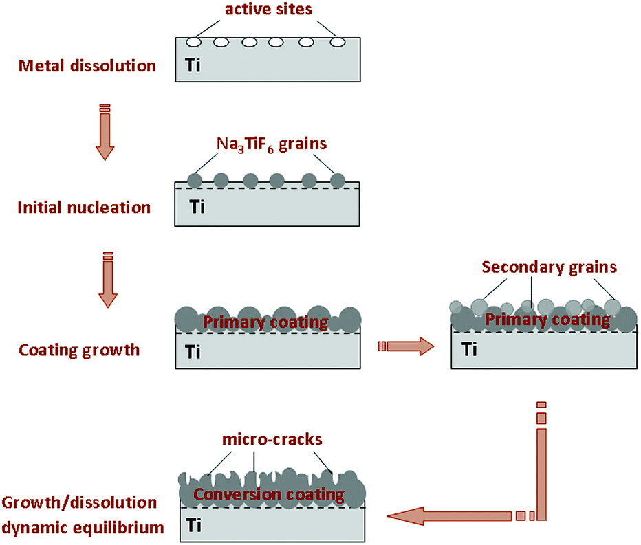 | ||
| Fig. 5 Deposition model of the fluoride–phosphate conversion coating on titanium alloy. | ||
The formation of the conversion coating was an electrochemically driven process.20,21,23 The titanium oxide and micro-anodes on the titanium surface were successively dissolved to Ti4+ (eqn (1) and (2)) when the titanium sample was immersed in the fluoride–phosphate conversion bath with a pH of 4.0–5.0.17 Meanwhile, the hydrogen evolution reaction occurred on the micro-cathode sites (eqn (3)). In this stage (0–45 s), the OCP decreased sharply, accompanied with the evolution of hydrogen. Simultaneously, Na3PO4 and NaF in the conversion bath were ionized, as shown in eqn (4) and (5). Besides, some Na3PO4 might be derivatized to Na2HPO4 and NaH2PO4 (eqn (6) and (7)) given the presence of H+.9,32
| TiO2 + 4H+ → Ti4+ + 2H2O | (1) |
| Ti − 4e → Ti4+ | (2) |
| 2H+ + 2e → H2↑ | (3) |
| Na3PO4 ↔ 3Na+ + PO43− | (4) |
| NaF ↔ Na+ + F− | (5) |
| 2Na+ + PO43− + H+ → Na2HPO4 | (6) |
| Na+ + PO43− + 2H+ → NaH2PO4 | (7) |
With the increase of Ti4+ on the electrode/solution interface, TiF4 might be formed when Ti4+ and F− achieve the solubility product (eqn (8));17,33 meanwhile, a few Ti4+ react with the oxygen in the bath and form a few TiO2 (eqn (9)). Afterwards, TiF4 might react with NaF step by step to form Na2TiF6 and Na3TiF6 nuclei (eqn (10) and (11)) at 45–120 s.26,34 As shown in Fig. 2a, the grains are formed on the partial sites of the substrate surface by 2 min.
| Ti4+ + 4F− → TiF4 | (8) |
| Ti4+ + O2 + 4e → TiO2 | (9) |
| TiF4 + 2NaF → Na2TiF6↓ | (10) |
| 3Na2TiF6 + Ti + 6NaF → 4Na3TiF6↓ | (11) |
With the extension of the conversion time, the Na3TiF6 grains gradually grow into larger sizes. At the same time, new nuclei are formed on the active sites of the titanium substrate. At 4 min, many large grains appear on the substrate surface (Fig. 2b). The nucleation and growth of Na3TiF6 grains happens continuously in this stage (120–600 s). When Na3TiF6 grains contact with each other (about 6 min), a complete conversion coating could be formed on the substrate surface, as shown in Fig. 2c. Thus, the OCP is increased greatly and the coating grows rapidly at 120–420 s.
As the reaction is carried out, the contact area between the substrate and conversion bath is reduced, and the supply rate of Ti4+ for the nucleation decreases, so the growth of the coating slows down. However, secondary grains could be formed on the primary conversion coating, via the stepwise reactions of conversion bath with Ti4+ from the micro-dissolution of the coating. So the conversion coating could still grow slowly in this stage (420–600 s), and the OCP is increased slightly. As shown in Fig. 2d, the secondary grains and the sub-layer appear on the surface of the complete inner coating.
After 600 s, the dissolving effect of the conversion bath on the coating may dominate the conversion process, and so the coating is in the dynamic stage of growth/dissolution. In this stage, the coating does not grow substantially, and the OCP tends to be stable.
After the conversion treatment, the samples are rinsed thoroughly with deionised water and dried at 100 ± 5 °C for 30 min. In this process, some Na3TiF6 grains react with O2 to form Na3TiOF5 (eqn (12)),26 as demonstrated in Fig. 3 and 4d and e.
| 2Na3TiF6 + O2 → 2Na3TiOF5 + F2 | (12) |
3.5 Corrosion resistance analysis
EIS has been shown to be an effective method to evaluate the corrosion resistance of conversion coatings.17,20,35,36 Fig. 6 shows Bode plots of the fluoride–phosphate conversion coating formed at different times. As shown in Fig. 6, although the bare titanium sample was not treated, the impedance spectroscopy for the uncoated sample still exhibited two time constants at medium and high frequencies. For the metal with a protective layer, the capacitive loop appearing at high frequencies is due to the charge-transfer process, while the capacitive loop at medium frequency is related to the barrier properties of the coating.36,37 It could be confirmed that the bare titanium sample covered a partially protective natural passive film, which resulted in the presence of medium-frequency resistance. However, the thin natural passive film could not effectively prevent the invasion of corrosive media, so the uncoated sample had an obscure time constant and a lower charge-transfer resistance at high frequencies.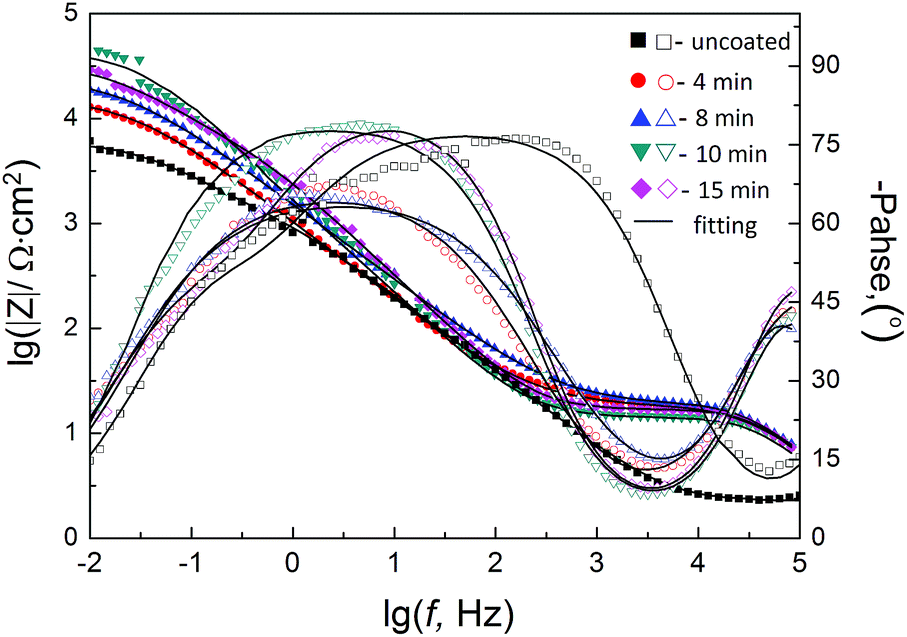 | ||
| Fig. 6 Bode plots of the fluoride–phosphate conversion coating formed at various times. | ||
Instead of a natural passive film, the fluoride–phosphate-conversion-coated samples were covered with a compact and protective barrier layer. The conversion coating could effectively avoid the contact between the corrosive media and the titanium substrate. Therefore, the impedance spectroscopy of the fluoride–phosphate-conversion-coated samples clearly appeared two time constants. Besides, the coated samples had a higher impedance value, especially the high-frequency impedance value compared to the bare sample. Whereas, the low-frequency impedance values of various coatings varied significantly with the conversion time, which indicated that the coverage and barrier property of the conversion coating changed with the conversion time.
According to the physical structure of the electrode, the electrical equivalent circuit shown in Fig. 7 was used to fit the EIS data of the conversion coating. In the circuit, Rs is the solution resistance, Rct and Cdl represent the charge-transfer resistance and the double-layer capacity at the coating/electrolyte interface, respectively, and Rf and CPEf reflect the coating resistance and the constant phase element delegated coating capacity of the conversion coatings. As shown in Fig. 6, the equivalent circuits provided an excellent fit to the experimental data over most of the frequencies.
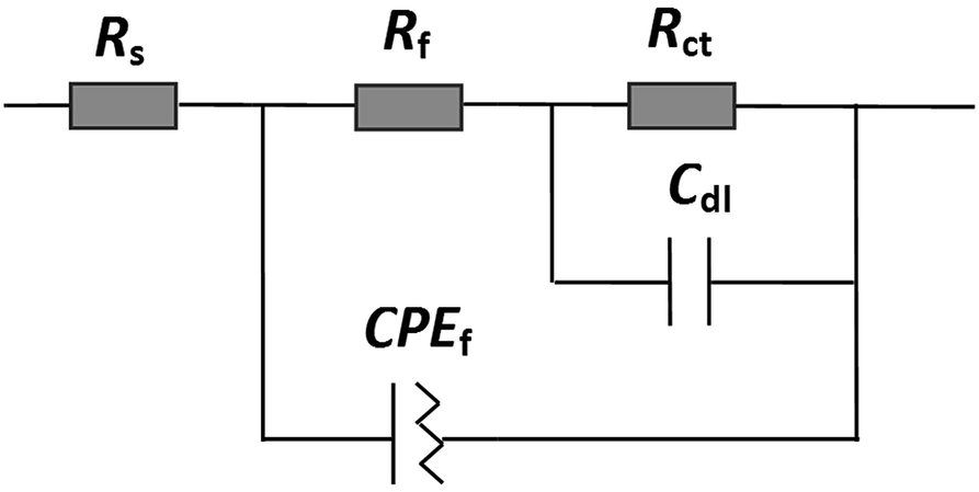 | ||
| Fig. 7 Equivalent circuit model of the fluoride–phosphate conversion coating formed on titanium alloy. | ||
Table 2 shows the fitting component values for the EIS. Generally, Rct could reflect the resistance of the corrosion reactions, while Rf and nf could illustrate the protection effect and integrity of the conversion coating, respectively.36–38 As shown in Table 2, the uncoated titanium sample also had a certain film resistance (Rf) due to the presence of the natural passive film. But this natural passive film only offered partial protection, which resulted in a low charge-transfer resistance (Rct). Compared to the bare sample, the fluoride–phosphate-conversion-coated samples had bigger Rf, nf and Rct values, which indicated better corrosion resistance. Besides, Rf, nf and Rct first increased but then decreased slightly with the increase in conversion time. The conversion coating formed at 10 min had the biggest Rct, Rf and nf, and so the conversion coating had higher integrity, bigger resistance and good corrosion resistance. The reasonable explanation for this was that as the grains increased and grew, the integrity of the coating (nf) increased with the increasing conversion time. A complete conversion coating had been formed at 6 min, moreover, both a complete inner layer and the secondary grains appeared on the surface at 10 min. Thus, the corrosion resistance of the coating increased within 10 min. However, after 10 min, the micro-dissolution effect of the conversion bath on the coating made the coating became rough, resulting in a decrease in the corrosion resistance of the coating.
3.6 Paint adhesion
Fig. 8a and d give the digital photos of the bare and fluoride–phosphate coated TC1 samples. It can be seen that a uniform and smooth grey conversion coating (Fig. 8d) was formed when the titanium sample was treated in a fluoride–phosphate bath for 10 min. This colouring effect enabled the researchers to visually monitor the coating development and to assess the quality of the resulting coating.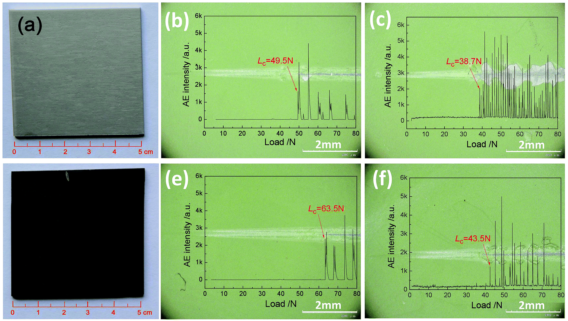 | ||
| Fig. 8 OM image (a, d), dry paint-adhesion (b, e) and wet paint-adhesion (c, f) of the TC1 alloy (a–c) and the fluoride–phosphate conversion treated alloy (d–f). | ||
Besides, the polyurethane coating was applied on the surface of the bare sample and the fluoride–phosphate coated sample. The dry and wet adhesion strength values of the paint coat to the substrates were measured by scratch testing. The scratch-induced surface photographs and AE signal curves of the various samples are shown in Fig. 8b, c, e and f. The critical load (LC) that the coating peeled off was confirmed by the scratch tracks and AE signals.5,25,38
As shown in Fig. 8b and e, the dry adhesion values (LC) of the polyurethane coating to the bare and fluoride–phosphate-coated sample were 49.5(±2.2) N and 63.5(±1.8) N, respectively. When the paint-coated samples were exposed to NaCl solution for 7 days, the wet-paint-adhesion strength of the polyurethane coating to the substrates significantly decreased, but the LC (43.5 ± 0.8) of the fluoride–phosphate treated sample was still higher than the LC (38.7 ± 0.3) of the untreated sample. The results are presented in Fig. 8 and show that the fluoride–phosphate conversion treatment resulted in an improvement in the polyurethane coating adhesion properties, especially the wet paint-adhesion. Many researchers have suggested that conversion coatings increased the paint-adhesion strength through increasing the wet ability and surface roughness.39,40 In this way, the fluoride–phosphate conversion coating with a granular cell structure, consisting of Na3TiF6, Na3TiOF5, TiO2 and TiF4, could create the stronger physical/chemical bonds between the paint and substrate, which might be a reasonable explanation for the increase in paint adhesion.
4. Conclusions
(1) A uniform, coherent and grey conversion coating with a thickness of 4–5 μm was prepared when TC1 titanium alloy was immersed in a fluoride–phosphate bath.(2) The growth process for the conversion coating was divided into four stages: substrate dissolving (<45 s); initial nucleation (45–120 s); coating growth (120–600 s) and dynamic equilibrium of the coating growth/dissolution (>600 s). Na3TiF6 nucleation occurred initially, and then increased and grew continuously to form the conversion coating. Some Na3TiF6 grains reacted with O2 to form Na3TiOF5 in the drying process at 100 ± 5 °C. The main composition of the conversion coating was Na3TiF6, Na3TiOF5, a little TiO2, TiF4 and phosphate derivatives.
(3) Fluoride–phosphate conversion coating improved the corrosion resistance of titanium alloy. The conversion coating formed at 10 min had better corrosion resistance than the others.
(4) Fluoride–phosphate conversion coating greatly enhanced the adhesion between the titanium alloy and organic coating.
Acknowledgements
The authors gratefully acknowledge the financial support of Open Foundation of National Defense Key Discipline Laboratory of Light Alloy Processing Science and Technology, Nanchang Hangkong University (Grant No. gf201501002).References
- R. R. Boyer, Mater. Sci. Eng., A, 1996, 213, 103–114 CrossRef.
- M. Peters, J. Kumpfert, C. H. Ward and C. Leyens, Adv. Eng. Mater., 2003, 5, 419–427 CrossRef CAS.
- W. Kaysser, Surf. Eng., 2001, 17, 305–312 CrossRef CAS.
- X. L. Liu, P. K. Chu and C. X. Ding, Mater. Sci. Eng., R, 2004, 47, 49–121 CrossRef.
- B. Liu, G. Y. Xiao, C. C. Jiang, Y. Z. Zheng, L. L. Wang and Y. P. Lu, RSC Adv., 2016, 6, 75365–75375 RSC.
- F. W. Eppensteiner and M. R. Jenkins, Met. Finish., 2000, 98, 497–509 CrossRef.
- P. Campesrini, G. Goeminne and H. Terryn, J. Electrochem. Soc., 2004, 151, B59–B70 CrossRef.
- T. S. N. S. Sanakara, Rev. Adv. Mater. Sci., 2005, 9, 130–177 Search PubMed.
- X. C. Zhao, G. Y. Xiao, X. Zhang, C. C. Jiang, H. Y. Wang and Y. P. Lu, Rare Met. Mater. Eng., 2014, 43, 306–309 CrossRef.
- P. Bhatia, Met. Finish., 2004, 102, 92 Search PubMed.
- H. Neuder and C.-T. Liu, J. Coat. Technol., 2002, 74, 37–42 CrossRef CAS.
- AMS 2486D, Conversion Coating of Titanium Alloys: Fluoride-Phosphate Type, 2004 Search PubMed.
- B. Valdez, S. Kiyota, M. Stoytcheva, R. Zlatev and J. M. Bastidas, Corros. Sci., 2014, 87, 141–149 CrossRef CAS.
- E. M. Palomino Luis, V. Aoki Idalina and G. de Melo Hercílio, Electrochim. Acta, 2006, 51, 5943–5953 CrossRef.
- C.-S. Liang, Z.-F. Lv, Y.-L. Zhu, S.-A. Xu and H. Wang, Appl. Surf. Sci., 2014, 288, 497–502 CrossRef CAS.
- M. G. S. Ferreira, R. G. Duarte, M. F. Montemor and A. M. P. Simões, Electrochim. Acta, 2004, 49, 2927–2935 CrossRef CAS.
- L. Li, J. He and X. Yang, Appl. Surf. Sci., 2016, 371, 488–493 CrossRef CAS.
- T. Chen, W. Li and J. Cai, RSC Adv., 2001, 1, 607–610 RSC.
- L. Li, W. W. Brandon and M. Swaina Greg, J. Electrochem. Soc., 2015, 162, C279–C284 CrossRef CAS.
- T. Lostak, A. Maljusch, B. Klink, S. Krebs, M. Kimpel, J. Flock, S. Schulz and W. Schuhmann, Electrochim. Acta, 2014, 137, 65–74 CrossRef CAS.
- A. Yi, W. Li, J. Du and S. Mu, Surf. Interface Anal., 2015, 47, 863–870 CrossRef CAS.
- D. Susac, X. Sun, R. Y. Li, K. C. Wong, P. C. Wong, K. A. R. Mitchell and R. Champaneria, Appl. Surf. Sci., 2004, 239, 45–49 CrossRef CAS.
- J. H. Nordlien, J. C. Walmsley, H. Østerberg and K. Nisancioglu, Surf. Coat. Technol., 2002, 153, 72–78 CrossRef CAS.
- F. O. George, P. Skeldon and G. E. Thompson, Corros. Sci., 2012, 65, 231–237 CrossRef CAS.
- X. L. Cai, Y. H. Xu, N. Zhao, L. S. Zhong, Z. Y. Zhao and J. Wang, Surf. Coat. Technol., 2016, 299, 135–142 CrossRef CAS.
- K. Borowiec, A. Przepiera and K. Kolbrecka, J. Therm. Anal., 1991, 37, 637–644 CrossRef CAS.
- A. H. Yi, W. F. Li, J. Du and S. L. Mu, Appl. Surf. Sci., 2012, 258, 5960–5964 CrossRef CAS.
- G. L. Georgiev, T. Sultana, R. J. Baird, G. Auner, G. Newaz, R. Patwa and H. Herfurth, Appl. Surf. Sci., 2008, 254, 7173–7177 CrossRef CAS.
- T. Sultana, G. L. Georgiev, G. Auner, G. Newaz, H. J. Herfurth and R. Patwa, Appl. Surf. Sci., 2008, 255, 2569–2573 CrossRef CAS.
- F. Fracassi and R. d'Agostino, Pure Appl. Chem., 1992, 64, 703–707 CrossRef CAS.
- P.-H. Lo, W.-T. Tsai, J.-T. Lee and M.-P. Hung, J. Electrochem. Soc., 1995, 142, 91–96 CrossRef CAS.
- F. Li and G. Wang, J. Mater. Eng. Perform., 2016, 25, 1864–1869 CrossRef CAS.
- M. Stancheva and M. Bojinov, Electrochim. Acta, 2012, 78, 65–74 CrossRef CAS.
- H.-H. Huang, Biomaterials, 2003, 24, 275–282 CrossRef CAS PubMed.
- M. E. Orazem and B. Tribollet, Electrochemical Impedance Spectroscopy, Wiley, John & Sons, Incorporated, 1st edn, 2008 Search PubMed.
- S. H. Zhang, G. Kong, J. T. Lu, C. S. Che and L. Y. Liu, Surf. Coat. Technol., 2014, 259, 654–659 CrossRef CAS.
- S. Y. Jian, Y. R. Chu and C. S. Lin, Corros. Sci., 2015, 93, 301–309 CrossRef CAS.
- X. Boddaert, G. Covarel, B. Bensaid, M. Mattei, P. Benaben and J. Bois, Thin Solid Films, 2013, 528, 194–198 CrossRef CAS.
- T.-W. Seo and J. Weon, J. Mater. Sci., 2012, 47, 2234–2240 CrossRef CAS.
- H. Vakili, B. Ramezanzadeh and R. Amini, Corros. Sci., 2015, 94, 466–475 CrossRef CAS.
| This journal is © The Royal Society of Chemistry 2017 |