DOI:
10.1039/C6RA27380G
(Paper)
RSC Adv., 2017,
7, 4983-4992
Regeneration of an efficient, solar active hierarchical ZnO flower photocatalyst for repeatable usage: controlled desorption of poisoned species from active catalytic sites†
Received
26th November 2016
, Accepted 30th December 2016
First published on 17th January 2017
Abstract
To date, reusable properties of nano photocatalysts (PCs) have been investigated for five to ten consecutive cycles with a mild decrease in photocatalytic performance. Systematic investigation on the decrease in photocatalytic performance and regeneration of the nanocatalyst after repeatable usage have rarely been reported. Hierarchical forms of self-assembled zinc oxide (ZnO) with a flower-like structure have been successfully synthesized by an aqueous solution based precipitation and show visible photocatalytic degradation efficiency of 98% against methylene blue (MB) dye in 120 min under natural solar irradiation and visible irradiation. Reusable catalytic properties were studied for 50 consecutive cycles and the degradation efficiencies obtained were around 85.9, 61.4, 47.3, 31.6 and 21.3% in 120 min of photo irradiation for 10, 20, 30, 40 and 50 consecutive repeatable cycles, respectively. On increasing the number of cycles, the photocatalytic efficiency of the ZnO flowers decreased due to adsorption of hydrocarbon molecules on the active sites of the catalyst, a phenomenon termed as catalytic poisoning. Furthermore, we show that the photocatalytic performance of ZnO hierarchical flowers could be completely reverted by a simple chemical treatment for further repeatable usage by removing the hydrocarbon groups on the active sites of the surface of the nanocatalysts. Our results provide insights into the effective visible photocatalytic nature and controlled process which removes the poisoning effect and regenerates the catalytic properties.
Introduction
Considering the importance of human safety and environmental problems, various efforts have been undertaken to overcome the environmental issues counterbalancing a clean and healthy environment. The advanced oxidation process (AOP) is a promising green technology for the degradation of toxic contaminants, especially for the removal of organic pollutants in environment remediation applications.1–3 Recently, researchers have focused on semiconductor photocatalysts (PCs) for AOP-based applications, which mainly involved the synthesis of efficient solar light driven PCs.4–7 In the field of semiconductor PCs, ZnO has acquired great attention due to its immense potential as a catalyst with abundant availability, non-toxicity and good photochemical stability.8,9 Previous reports show that ZnO based nanocatalysts are highly efficient under ultraviolet (UV) and visible irradiation.10–15 Efficiency of the catalytic response has influence by the morphology as well as by the effective carrier separation and production of reactive oxygen species (ROS) over the catalytic surface.15 However, catalytic stability and multiple reusable properties of the nanocatalyst are the critical deciding factors for commercializing the AOPs for the environment remediation applications. Several investigations about catalytic loss,16–18 sulfur19 and hydrocarbon impurities20 based poisoning of catalysts and regenerating the catalytic performances were described on gas phase oxidation of heptane, petroleum refining and photochemical based industries.20–22 Reusability of the nanocatalysts is the one of the important criteria for the utilization of nanocatalysts for environmental remediation applications. Re-using of nanocatalysts is vital owing to the rigid environmental safety regulations for their disposal and economic benefit.27 So far, majority of the reports show that reusable properties of TiO2, WO3, ZnO nanocatalysts were studied up to 10 cycles and further utility of the catalyst were not much clearly investigated.18,23–26 To date, articles present reusability of the photocatalyst tested upto 5 to 10 cycles and report good reusability. However, detailed study on reusability (after multiple cycles) and stability of the photo catalyst is missing.
Our previous article reports on morphology (rods, brooms, spindles, stars, needles, hierarchical flowers, multipods) controlled synthesis of ZnO nanostructures and inter-relation between their (i) morphology, (ii) surface defects (iii) ROS production and (iv) photocatalyst properties.15 Hierarchical ZnO nanoflowers show efficient PC performance compared to the other nanostructures and reusability of the same was studied upto 10 cycles.
In the present work, to get better insight on the catalytic stability and reusability, reusable properties of hierarchical ZnO flowers were studied extensively upto 50 cycles. The structural and functional properties of the reused hierarchical ZnO flower catalysts reveal that after multiple reusable cycles, catalytic surface were poisoned due to chemisorbed hydrocarbon groups on the active catalytic sites which termed as catalyst poisoning. A simple, cost effective, chemical treatment process has been proposed to regenerate the poisoned hierarchical ZnO flower catalyst to revert back to its maximum photocatalytic performance. The results could be useful for designing and processing of photocatalysts for repeatable usage.
Experimental
Synthesis of hierarchical ZnO flowers
All chemicals were purchased from Himedia and used without further purification. Growth parameters of hierarchical ZnO flowers are reported in detail in our previous publication.15 Briefly, equal mole of Zn(NO3)2·6H2O and HMTA were taken in separate 150 mL beakers and stirred for 5 min. After stirring, HMTA was added drop wise into Zn(NO3)2 precursor and stirred. After stirring for 10 min at room temperature, 10 mL of ammonia was mixed slowly into the solution. The solution was placed in a constant temperature bath and heated at 97 °C for 4 hours. The samples were cleaned and centrifuged using distilled water and ethanol three to four times and baked at 100 °C for 30 min.
Characterization
The phase and crystalline structure of the samples were studied using Phillip X'pert Pro Advance Powder X-ray diffractometer (Cu-Kα radiation; λ = 1.5418 Å). The morphology of the nanostructures was studied by ZEISS scanning electron microscope. A JEOL JEM-2100 high resolution transmission electron microscope (HRTEM) operated at 200 kV was used for the detailed microstructural characterization of the nanostructures. UV-Vis absorbance spectra of the samples were recorded using JASCO V620 UV-Vis spectrophotometer. A HORIBA JOBIN YVON spectro fluoromax-4/photoluminescence spectrophotometer was used for obtaining the photoluminescence spectra (PL) of the samples. The specific surface area (SSA) was evaluated using the Brunauer, Emmett, and Teller (BET) nitrogen adsorption method (Micromeritics ASAP 2030). Fourier's Transfer Infrared Spectrometer (FTIR) spectra were recorded by Bruker Tensor 27, spectrometer over the range 4000–400 cm−1 using KBr as the reference. UV-Vis DRS measurement was acquired using a JASCO V620 UV-Vis spectrophotometer. The surface analysis of the sample was carried out by using X-ray photoelectron spectroscopy (XPS). All binding energies were referred to the C 1s peak (284.6) arising from surface hydrocarbons (or adventitious hydrocarbons).
Photocatalytic study
The photocatalytic activity of ZnO was evaluated using Methylene Blue (MB) as model contaminant. The reactions were performed under dark, UV light (30 W Hg lamp (ZF-1 UV, Philips, China), setup with peak emission at λ = 365 nm), under visible irradiation (75 W xenon lamp with the UV cut off filter (λ > 400 nm) (Lee type 226 (USA))), under natural sunlight (sunlight, 905 Lm per m2) with the UV cut off filter (Lee type 226 (USA)) on a normal sunny day between 8.00 a.m and 4.00 p.m under the shadows in order to avoid the evaporation of solution through heat effect. The light intensity was constantly checked every 30 min using lux meter.15 In a photo reaction experiment, 100 mg of ZnO was suspended in a 100 mL aqueous solution containing 15 mg L−1 of MB in neutral pH. Prior to irradiation, the solution was stirred for 30 min in the dark to ensure establishment of an adsorption–desorption equilibrium on the surface of the PC. The absorbance behaviour of MB was monitored every 30 min with an overall reaction time of 180 min by UV-Vis spectrophotometer ranging from 200 to 800 nm. The concentration of organic dyes was determined by measuring the absorption intensity at the maximum absorbance wavelength of the supernatant (MB = 661 nm) by using a UV-Vis spectrophotometer. Similar experiment was carried out without any photo illumination sources in order to measure the catalytic behaviour under dark. The degradation efficiency (η) of the dye wastewater could be defined as follows.28| |
 | (1) |
where C0 is the initial dye concentration, Ct is the dye concentration at a certain reaction time t (min). Catalytic efficiency of commercial ZnO (sigma Aldrich) was investigated and compared with the hierarchical ZnO flower catalyst. The poisoning effect due to absorbance of the dye molecules on the nano structural surface was studied using Tensor 27 Fourier's Transfer Infrared Spectrometer.
Active species trapping, superoxide and hydroxy radicals quantification
For detecting the active species during the photocatalytic reaction, hydroxyl radicals (˙OH), superoxide radicals (O2˙) and holes (h+) were investigated by adding 1.0 mM IPA (isopropyl alcohol, a quencher of ˙OH), BQ (benzoquinone, a quencher of O2˙) and TEOA (triethanolamine, a quencher of h+), respectively.29 Nitroblue tetrazolium (NBT) (100 mM, exhibiting an absorption maximum at 259 nm), p-chlorobenzoic acid (CBA) (100 mM, exhibiting an absorption maximum at 312 nm) were used as the indicators to determine the amount of super oxide (O2˙−) and hydroxyl radicals (OH˙) generated from the nanocatalyst. NBT was stored for no longer than one day at 4 °C. After UV illumination for different periods of time, 1 mL of the suspension was sampled and injected into a quartz vial. The concentration of NBT and p-CBA (the product resulting from the reduction of NBT and p-CBA by O2˙−, OH˙ respectively) were measured using a UV-Vis spectrophotometer (JASCO 620) at 257 nm, 312 nm respectively. Exposure tests were run for different time periods, for up to 180 min as the photocatalytic degradation test, with NBT and p-CBA replacing the dye.30–32
Reusable photocatalytic properties
Reusability tests were conducted for the hierarchical ZnO flowers. Briefly, the selected photocatalyst (after being used in degradation test of MB) was allowed to settle down naturally in the reactor (∼30 min). Because of it micro sized morphology it settles down fast and was rinsed thrice with distilled water. The washed material was then dried at 60 °C for 5 hours before using in a new MB degradation experiment. Fifty consecutive additional tests were conducted.
Results and discussion
ZnO structures of various morphologies such as rods, brooms, buds, spindles, stars, hierarchical flowers and multipods (Fig. S1, ESI†) by simply controlling the Zn supersaturation in the growth solution.15 Reusable properties of ZnO structures revealed decrease in PC activity after 10 cycles. Among the various ZnO morphologies, hierarchical ZnO flowers15 showed best photocatalytic activity (Fig. S2 and S3, ESI†) and therefore chosen for elaborate reusable studies presented in this work.
Crystal phase and morphology analysis
The phase and crystallinity of the as-synthesized product was studied by XRD and the resultant XRD pattern is shown in Fig. 1. The intense and sharp diffraction peaks suggest that the product was highly crystalline and well matched with a standard data card (JCPDS-80-0075; a = 3.259 Å and c = 5.209 Å) indexed as hexagonal phase ZnO. The calculated lattice parameters are; a = 3.282 Å and c = 5.249 Å. No other impurities were detected, demonstrating that the products are of high purity with single crystalline phase. In addition, the width of the diffraction peaks indicate that the sample product comprises of smaller crystallites. Fig. 2a and inset shows the SEM images of hierarchical ZnO flowers with varying magnifications. Fig. 2a indicate that the product is composed of flower-like structure and has the dimension of 400–800 nm with multiple facets of size 80–100 nm. As hierarchical structure of the as-synthesized ZnO is further elucidated by TEM studies (Fig. 2b–d), it is observed that the ZnO flowers comprise of needle like structures and nanoparticles of size about 200 and 15 nm respectively. Fig. 2c and d shows the HRTEM images of the as-synthesized ZnO in which the cluster of nanograins are oriented and assembled to form a flower-like hierarchical architecture. The growth mechanism of the ZnO hierarchical flowers is beyond the scope of this paper, detailed growth mechanisms are reported in our previous publication.15
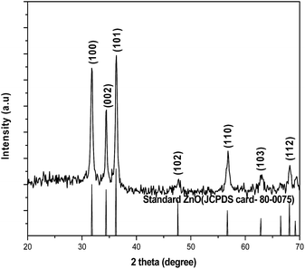 |
| | Fig. 1 XRD pattern of hierarchical ZnO flower catalyst. | |
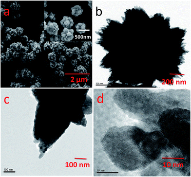 |
| | Fig. 2 (a) SEM (b, c) TEM micrographs (d) HRTEM micrograph of hierarchical ZnO flowers. | |
Elemental analysis
In order to determine the elements and their oxidation states in ZnO flowers, XPS study was carried out. The binding energy peaks of Zn and O are shown in XPS spectrum (Fig. 3a). No peaks of other elements can be observed. In Fig. 3b, the O1s profile found to be asymmetric in nature and can be deconvoluted into to three peaks locating at 529.9, 531.4 and 532.3 eV, respectively, indicating three different kinds of O species in the sample. The peak centered at 529.9 eV is closely associated with the lattice oxygen (OL) of ZnO, the peak at 531.4 eV is attributed to the oxygen of surface hydroxyl (OH), while the peak at 532.3 eV is due to the chemisorbed oxygen (Oa). It has been shown that surface hydroxyls (OH) of the photocatalyst play a significant role for a photocatalytic oxidation process.33 Fig. 3c presents the XPS spectra of Zn 2p, and the peak positions of Zn 2p1/2 and Zn 2p3/2 are at 1044.4 eV and 1021.5 eV respectively and the different between the two peaks are 23.1 indicating that Zn is in the Zn2+ valence state.34
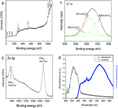 |
| | Fig. 3 XPS spectra of as synthesised flower like ZnO (a) survey spectrum, (b) O 1s peak, (c) Zn 2p peak and (d) absorbance and luminescence spectra of hierarchical ZnO flower structures. | |
Optical properties
Fig. 3d shows the optical absorption and photoluminescence spectra of hierarchical ZnO flowers. ZnO shows a strong absorption of UV and has slight absorption in the visible region of light. This reveals that ZnO can be used as a UV and visible light active semiconductor photocatalytic material (Fig. S4†). Room temperature PL spectra mainly consist of two emission bands: a band at 416 nm (2.98 eV) and a strong greenish band at 530 nm (2.34 eV). The strong UV emission at 416 nm corresponds to the electron–hole recombination from the CB to VB.35 The green emission is due to surface oxygen defects in ZnO flower like hierarchical structures.15 As the ZnO flowers have higher rate of oxygen vacancy states, it may have the photocatalytic degradation efficiency in the visible and UV region.15
Photodegradation study
Fig. 4 shows the photocatalytic degradation properties of as-prepared hierarchical ZnO flowers structures against heteroaromatic MB. Hierarchical ZnO flowers show promising photocatalytic activity under UV and visible photo irradiation. Moreover, the variation in MB degradation efficiency is consistent with the different light irradiation used (Fig. 4a). As shown in Fig. 4a, the degradation efficiency is about 2.8%, 98.8%, 99.3 and 98.9%, under dark, UV light, visible light and sunlight irradiation for 180 min respectively. In the case of visible light irradiation, ZnO exhibits better photocatalytic behaviour than other conditions and showed complete degradation (98.4%) of MB in 120 min.
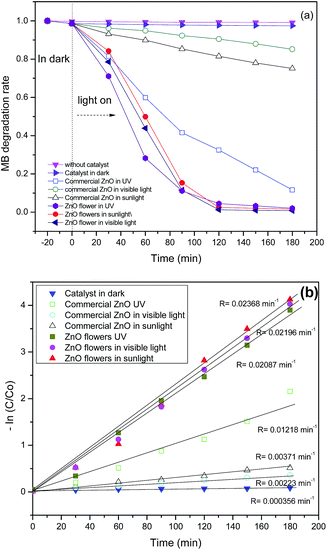 |
| | Fig. 4 Photocatalytic performance of as synthesised and commercial ZnO: (a) degradation efficiency and (b) degradation kinetics of MB dye solution under various photo illumination. | |
It is clear from the figure that the PC degradation performance of commercial ZnO varies with different irradiation. Commercial ZnO show maximum PC degradation efficiency about 58% for 90 min against MB dye under UV illumination. Whereas, hierarchical ZnO flowers show relatively higher PC activity about 80 to 90% for 90 min against MB dye under UV, visible light and sun light irradiation. This clearly shows that hierarchical ZnO flowers exhibit higher degradation efficiency compared to that of commercial ZnO. The photocatalytic efficiency of the hierarchical ZnO flowers were compared with the commercially available ZnO hierarchical structures under different photo illumination sources and the degradation rate were calculated from the Fig. 4b. From the above experimental results, it is clear that the ZnO hierarchical flower has higher photocatalytic activity and more interestingly, it is found to be a suitable candidate for natural sunlight driven photocatalytic application. The photo degradation results show that (i) no notable degradation takes place without catalyst (ii) under dark conditions, mild adsorption of MB with ZnO is observed (iii) ZnO exposed to UV and visible light sources has excellent photocatalytic degradation activity, which degrade MB completely (98.2%) in 120 min. (iv) Optically active defect states play vital role in improving the visible photocatalytic properties and this has already conformed from our previous publication.15
Effect of pH role on dye solution was investigated since catalytic degradation efficiency varied with respect to pH. Fig. 5 shows the effect of dye degradation efficiency at different pH from 3 to 11 for ZnO hierarchical structures under UV and visible irradiation. It is observed that the degradation rate increases with increase in pH up to 9 and then it decreases. Under pH 9 the degradation rate is higher due to the catalyst zero point charge which increases the surface charge density of the catalyst thus making it negatively charged.34 It effectively increases the adsorption of dye molecules to the catalyst surface and promotes the interaction between the negatively charged catalysts with dye molecules and increases the electrostatic attraction between dye anions. A similar trend is observed with the commercial ZnO (Fig. 5c). To further confirm this, an experiment to find out the adsorption of dye in dark at different pH was carried out (figure not shown). The rate of adsorption of MB on the ZnO catalytic surface, after the attainment of adsorption equilibrium, are 0.04, 0.74, 1.46, 5.74 and 3.74% at pH 3, 5, 7, 9 and 11 respectively. ZnO hierarchical structures has high adsorbance of dye molecules at pH 9. At higher (above 11) and lower (below 7) pH, the electrostatic attraction between dye anions and negatively charged catalyst becomes weak resulting in reduced adsorption. Photo irradiation of hierarchical ZnO flower exhibits higher photocatalytic efficiency owing to its relatively higher surface area (Fig. S6†) and effective production of charge carriers on the catalyst surface.15
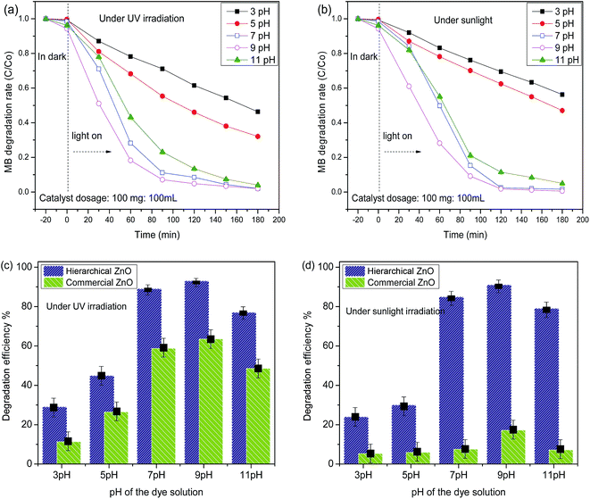 |
| | Fig. 5 Effect of pH on the photocatalytic performance of hierarchical ZnO flowers respective with time under (a) UV and (b) sunlight irradiation and comparison with commercial ZnO catalyst under (c) UV and (d) sunlight irradiation in 90 min. | |
Photocatalytic degradation mechanism
Under UV and visible light irradiation ZnO hierarchical flowers completely degraded the MB with the irradiation time of 180 min. This can be due to the fact that the additional charge carriers (e−/h+) and more reactive species (OH−) are generated in the system as a result of the successive absorption of visible light photons by ZnO. As the band gap of ZnO does not lie in the visible region (>3.2 eV), it is evident that oxygen related defect states effectively play a vital role in superior visible light photo absorption behaviour thus showing efficient photocatalytic ability in the visible region (Fig. S7†).10,15 The possible photo degradation mechanism of the organic pollutant was explained in our previous manuscript.15 Upon visible light irradiation, electron–hole pairs are generated and the photo generated electrons (e−) occupy the lower edge of the conduction band (CB) and the positive holes (h+) at the upper edge of the valance band (VB).36,37 Thus, the generated charge carriers can either recombine (not favourable to photocatalysis) or rapidly diffuse to the surface of ZnO serving as redox sources. The holes in the VB are readily scavenged by hydroxyl (OH−) ions (hole acceptor) leading to hydroxyl radicals (OH˙) and the photo excited electrons in the CB are scavenged by lattice oxygen (O˙2 electron acceptor) through H2O/OH− to form superoxide radicals (O˙2) (eqn (2) and (3)).38| |
|
ZnO (h+) + OH− → ZnOOH (abs)
| (2) |
| |
|
ZnO (e+) + O2 → ZnOO2 (abs)
| (3) |
| |
|
O2˙ + H2O → HO2˙ + OH−
| (5) |
| |
|
HO2˙ + H2O → H2O2 + OH˙
| (6) |
Fig. 6 shows the reactive oxygen species production under UV and visible irradiation for hierarchical ZnO flowers. Super oxides are the major productive reactive oxygen species on ZnO system under photo irradiation.39 Super oxides were highly evolved under solar irradiation as compared to UV illumination and the results were in corroboration with its photocatalytic properties. The newly formed superoxide radicals (O2˙) further react with h+, and H2O and produce increased number of OH− in solution which leads to rapid oxidation of MB (Fig. S8†). Fig. 7 display the trapping experiment of the active species during the photocatalytic reaction of commercial ZnO and hierarchical ZnO flower respectively. Fig. 7 shows that the PC degradation efficiency of commercial ZnO and hierarchical ZnO flowers against MB dye for 90 min under UV irradiation. Commercial ZnO show PC degradation efficiency about 58% and hierarchical ZnO flowers show relatively faster degradation about 89% for 90 min (black bars, Fig. 7). It is interesting to see that the degradation efficiency of commercial ZnO (58%) decreased to 11%, 51% and 55% in the presence of super oxide (red bars), hydroxyl radical (blue bars) and hole (pink bars) quenchers respectively. The drastic decrease of PC efficiency (down to 11%) in the presence of super oxide quencher (BQ) and a decrease in smaller extent in the presence of hydroxyl radical (51%) and hole (55%) quenchers indicate that photogenerated electrons are the dominant factor influencing the degradation process. Since quenching of superoxide species drastically reduces the PC degradation efficiency whereas quenching of hydroxide radical and hole producing does not influence the PC degradation efficiency. On the other hand, PC degradation efficiency of hierarchical ZnO flowers (89%) substantially decreased to 31%, 49% and 52% in the presence of super oxide (red bars), hydroxyl radical (blue bars) and hole (pink bars) quenchers respectively. This indicate that both photogenerated electrons and holes are responsible for enhanced degradation efficiency of hierarchical ZnO flowers. This clearly shows that relatively more number of photogenerated holes are reaching to the surface in the case of hierarchical ZnO flowers compared to that of the commercial ZnO and thus show relatively higher PC efficiency.
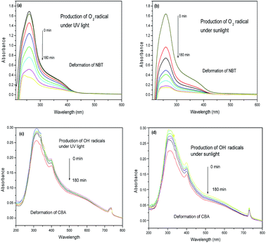 |
| | Fig. 6 Deformation of NBT and CPA with the presence of hierarchical ZnO flowers under different photo illumination (a, c) in UV light and (b, d) in natural sunlight. | |
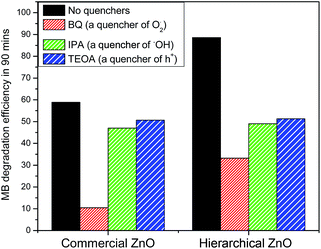 |
| | Fig. 7 Trapping of active species on commercial and hierarchical ZnO during the photocatalytic degradation of MB dye under UV irradiation for 90 min. | |
Reusability of the catalyst
The reusability of hierarchical ZnO flowers was tested for the degradation of MB under identical reaction conditions. After complete degradation, the catalysts were separated and washed with deionized water. The recovered catalysts were dried and used for the next run. Fig. 8a shows the results of MB degradation for ten runs of the hierarchical ZnO structures. Hierarchical ZnO flowers exhibit MB degradation efficiency are 98.2–85.4% from 1st to 10th runs respectively for 180 min. There is a significant change in the degradation efficiency of ZnO for MB dye after multiple cycles. In order to gain better understanding of the repeatable catalytic degradation, reusable catalytic performances were studied for 50 cycles. A drastic decrease in photocatalytic efficiency was found on increasing the reusable cycles above 10.
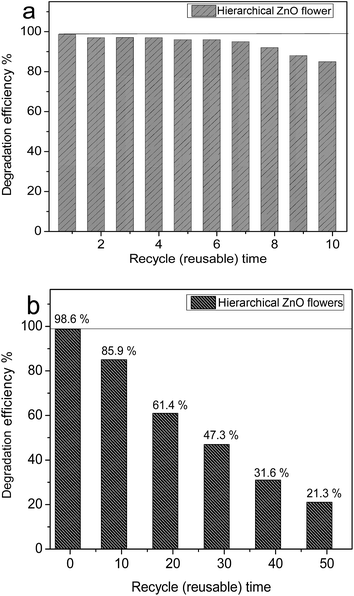 |
| | Fig. 8 Reusable degradation activity for ZnO flower (a) upto 10 cycles and (b) for upto 50 cycles (MB: 15 mg L−1, ZnO suspension 100 mg/100 mL, time 3 h). | |
Fig. 8b shows the reusable catalytic properties upto 50 cycles. Catalyst loss during multiple uses was avoided by quick precipitation in a specifically designed reactor. On increasing the number of cycles, the photocatalytic activity was found to reduce due to the absorbance of degraded dye molecules onto the surface of ZnO.
Poisoning effect on catalytic surface
Catalyst poisoning effect involves the compounds which bonds chemically to the active surface sites of a catalyst.21 Photogenerated charge carriers generates H2O2 and OH˙ which interact with cationic sulfur group and hetero aromatic rings in MB and produce sulfoxide and intermediate products. These sulfoxide groups further oxidize to sulfone, causing the definitive dissociation of MB resulting in the formation of volatile low molecular weight compounds such as CO2, H2O, NH4+, NO3− and SO42− ions.40,41 For further understanding the catalyst poisoning effect, functional properties on hierarchical catalyst surface before and after degradation cycles, were investigated.
Fig. 9 shows the FTIR spectrum of a (i) pure MB dye solution (ii) ZnO hierarchical flowers before its use for photo degradation (iii) ZnO hierarchical flower catalyst after 10 cycles of photo degradation. The different functional groups associated with the MB absorption peaks are H–OH stretching (3428 cm−1), CH![[double bond, length as m-dash]](https://www.rsc.org/images/entities/char_e001.gif) N (1600 cm−1), C
N (1600 cm−1), C![[double bond, length as m-dash]](https://www.rsc.org/images/entities/char_e001.gif) C (1500–1400 cm−1), –CH2 or –CH3 (1400–1300 cm−1), –C–N (1254 cm−1), N–N (1222 cm−1), –C–O (1200–1000 cm−1) and –N–O (947 cm−1) the main chromophores.42 The magnified view of the spectra reveal the emergence of C
C (1500–1400 cm−1), –CH2 or –CH3 (1400–1300 cm−1), –C–N (1254 cm−1), N–N (1222 cm−1), –C–O (1200–1000 cm−1) and –N–O (947 cm−1) the main chromophores.42 The magnified view of the spectra reveal the emergence of C![[double bond, length as m-dash]](https://www.rsc.org/images/entities/char_e001.gif) C, C
C, C![[double bond, length as m-dash]](https://www.rsc.org/images/entities/char_e001.gif) O peaks43 around 1400 cm−1 and 1000 cm−1 for the reused ZnO flowers compared to the unused ZnO hierarchical flowers indicating the adsorption of degraded molecules on the ZnO hierarchical flowers. The chemisorbed carboxylate groups on ZnO surface (Fig. 9b) decreases the degradation efficiency on increasing the number of cycles of photocatalysis for more than 10 times.
O peaks43 around 1400 cm−1 and 1000 cm−1 for the reused ZnO flowers compared to the unused ZnO hierarchical flowers indicating the adsorption of degraded molecules on the ZnO hierarchical flowers. The chemisorbed carboxylate groups on ZnO surface (Fig. 9b) decreases the degradation efficiency on increasing the number of cycles of photocatalysis for more than 10 times.
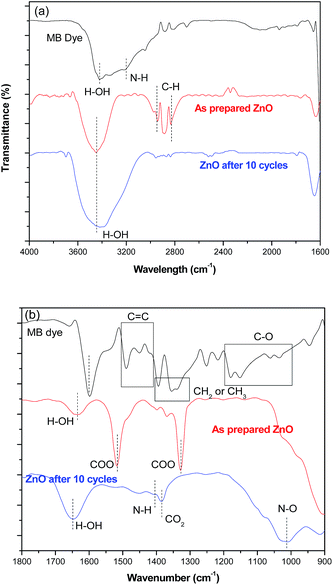 |
| | Fig. 9 FTIR spectra of ZnO flowers, before and after the degradation process under UV irradiation (a) ranges from 4000–1600 cm−1 and (b) ranges from 1800–900 cm−1. The pure MB were used as a reference sample. | |
Regeneration of hierarchical ZnO flower catalysts
The photocatalytic performance of hierarchical ZnO catalysts could be regenerated by removing the adsorbed molecules from the surface of the catalyst. In our investigation, on increasing the pH of the dye solution, dye–catalyst interaction increased resulting in increase of both degradation efficiency and dye adsorption (Fig. 5). From the observations, at lower pH, the dissolution rate of the catalyst was high as compared to the higher pH. Therefore, it is proposed to disperse the used catalyst in the lower pH solution to strip the adsorbed functional group from the active sites of the catalyst. Mild HCl acid treatment is proposed to remove the adsorbed dye molecules on the hierarchical catalyst surface. Parameters such as concentration of the acid and the treating time were optimized to remove the adsorbed dye molecules without damaging the ZnO hierarchical catalyst morphology. The hierarchical ZnO catalyst used consecutively for 50 degradation cycles were treated with 0.0001 M HCl acid for different time durations and their degradation performances are shown in Fig. 10. It is clear from the Fig. 10 that the photocatalytic performance of the ZnO hierarchical catalyst treated with 0.0001 M of HCl for 20 min reverted to its maximum performance. The hierarchical catalyst treated for 5 min showed slower catalytic performance revealing that still the surface has some poisoning effect. Whereas increasing the treatment time to 40 min resulted in poor performance probably due to the adsorption of other functional groups and the higher erosion of catalyst surface. More detailed investigation is required for better understanding. Thus, ZnO hierarchical catalyst treated for 20 min is found to be optimum to nearly remove the adsorbed dye molecules to regain its maximum photocatalytic performance.
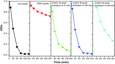 |
| | Fig. 10 Degradation of MB under UV irradiation in the presence of ZnO flowers (a) 1st cycle, (b) 50th cycle, (c) acid treatment of 5 min on 50 times reused catalyst, (d) acid treatment of 10 min on 50 times reused catalyst, and (e) acid treatment of 20 min on 50 time reused catalyst (0.001 N of mild HCl were used for the acid treating). | |
Fig. 11a and b shows the poisoned hierarchical ZnO flowers after mild HCl acidic treatment for 5 min and 20 min respectively compared with the poisoned ZnO catalyst. The intensity of the peaks in the range of 1400–1500 cm−1 that corresponds to the C![[double bond, length as m-dash]](https://www.rsc.org/images/entities/char_e001.gif) O bonds decreased on increasing the duration of acid treatment. The peak at 1319 cm−1 and 1530 cm−1 that corresponds to C
O bonds decreased on increasing the duration of acid treatment. The peak at 1319 cm−1 and 1530 cm−1 that corresponds to C![[double bond, length as m-dash]](https://www.rsc.org/images/entities/char_e001.gif) O and O–H bending vibrations43 respectively diminishes gradually for acid treated catalysts. FTIR spectra significantly demonstrate that due to poisoning effect, more number of C
O and O–H bending vibrations43 respectively diminishes gradually for acid treated catalysts. FTIR spectra significantly demonstrate that due to poisoning effect, more number of C![[double bond, length as m-dash]](https://www.rsc.org/images/entities/char_e001.gif) C stretching bonds were adsorbed on ZnO catalyst which inactivates the catalytic surface. On treating the poisoned catalyst with mild acid, successful removal of the C
C stretching bonds were adsorbed on ZnO catalyst which inactivates the catalytic surface. On treating the poisoned catalyst with mild acid, successful removal of the C![[double bond, length as m-dash]](https://www.rsc.org/images/entities/char_e001.gif) C on the catalytic surface takes place and its catalytic activity is regained. With optimized concentration of acid cleaning, removal of the adsorbed toxic dye molecules from the catalyst surface is made possible and the catalyst regain its catalytic activity. In order to study the stability of ZnO, XRD and SEM analysis were performed for samples of pure hierarchical ZnO flowers before degradation and after degradation for many cycles (Fig. 12). It could be observed that the characteristic peaks for ZnO are identical for all the treated samples compared with the pure ZnO confirming its catalytic ability and phase stability.
C on the catalytic surface takes place and its catalytic activity is regained. With optimized concentration of acid cleaning, removal of the adsorbed toxic dye molecules from the catalyst surface is made possible and the catalyst regain its catalytic activity. In order to study the stability of ZnO, XRD and SEM analysis were performed for samples of pure hierarchical ZnO flowers before degradation and after degradation for many cycles (Fig. 12). It could be observed that the characteristic peaks for ZnO are identical for all the treated samples compared with the pure ZnO confirming its catalytic ability and phase stability.
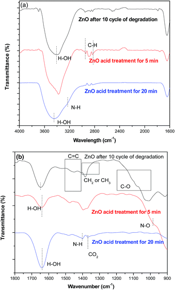 |
| | Fig. 11 FTIR spectra of ZnO flowers, before and after acid treatment for the removal of poisoning effect on the catalytic surface (a) ranges from 4000–1600 cm−1 and (b) ranges from 1800–900 cm−1. | |
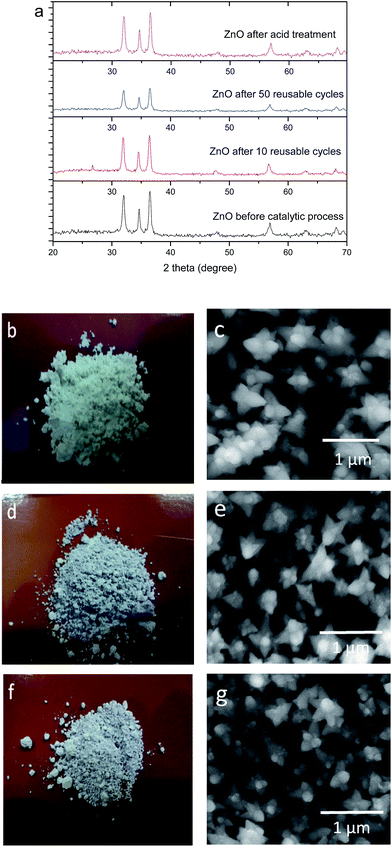 |
| | Fig. 12 Structural and morphological properties of ZnO flowers before, after photocatalytic reaction and after acid treatment (a) XRD pattern, (b–g) optical and FESEM images of ZnO hierarchical flower. (b, c) as-prepared, (d, e) after 50 catalytic cycles and (f, g) after mild acid treatment. | |
Fig. 12a shows the XRD spectra of fresh and used ZnO PC (50 cycles). It was found that the crystal structure of ZnO PC did not change after 50 cycles and further acid/chemical treatment, indicating the stability of the PC. Hence the catalyst can be reused for continuous treatment of waste dye water. Further morphological investigation also revealed that there is no significant morphological change after photocatalytic and chemical treatment process. TEM images of the mild acid treated ZnO flowers does not shows any influence over the morphology of the hierarchical flowers after mild acid treatment (Fig. S9†). Further degradation studies on the regenerated hierarchical ZnO flowers showed in Fig. S10, ESI.†
Conclusions
In summary, solar and visible active hierarchical flower-like ZnO catalysts were synthesized by a solution-based process and reusable catalytic properties were studied upto 50 consecutive cycles. The optically active defects play a vital role in improving the photocatalytic properties during both UV and visible irradiation. After 8 reusable cycles the ZnO flower shows detraction on its catalytic efficiency and nearly lose its catalytic ability by 50 cycles due to the adsorption of hydrocarbon groups over the active sites. Controlled chemical treatment revert the maximum catalytic performance by stripping the adsorbed functional groups from the surface active sites for repeatable usage.
Acknowledgements
The authors KSR and RTR would like to thank the Department of Science and Technology, Government of India, for financial support under the Nano Mission Project (SR/NM/NS-113/2010-BU (G)).
References
- M. R. Hoffman, S. T. Martin, W. Choi and D. W. Bahnemann, Chem. Rev., 1995, 95, 69–96 CrossRef.
- K. Bin and S. S. Madej, Ozone: Sci. Eng., 2012, 34, 136–139 CrossRef.
- B. Ning, N. Graham, Y. Zhang, M. Nakonechny and M. G. El-Din, Ozone: Sci. Eng., 2007, 29, 153–176 CrossRef CAS.
- J. Yu and A. Kudo, Adv. Funct. Mater., 2006, 16, 2163–2169 CrossRef CAS.
- S. Kohtani, J. Hiro, N. Yamamoto, A. Kudo, K. Tokumura and R. Nakagaki, Catal. Commun., 2005, 6, 185–189 CrossRef CAS.
- M. Izadifard, G. Achari and H. L. Cooper, Catalysts, 2013, 3, 726–743 CrossRef.
- Y. Yang, T. Zhang, L. Le, X. Ruan, P. Fang, C. Pan, R. Xiong, J. Shi and J. Wei, Sci. Rep., 2014, 4, 7045 CrossRef CAS PubMed.
- C. Lizama, J. Freer, J. Baeza and H. D. Mansilla, Catal. Today, 2002, 76, 235–246 CrossRef CAS.
- X. Pian, B. Lin, Y. L. Chen, J. D. Kuang, K. Z. Zhang and L. M. Fu, J. Phys. Chem. C, 2011, 115, 6531–6539 CAS.
- J. Wang, Z. Wang, B. Huang, Y. Ma, Y. Liu, X. Qin, X. Zhang and Y. Dai, ACS Appl. Mater. Interfaces, 2012, 4, 4024–4030 CAS.
- S. Baruah, R. F. Rafique and J. Dutta, Nano, 2008, 3, 399–407 CrossRef CAS.
- M. Y. Guo, A. M. Ching Ng, F. Liu, A. B. Djurišić, W. K. Chan, H. Su and K. S. Wong, J. Phys. Chem. C, 2011, 115, 11095–11101 CAS.
- D. Chen, Z. Wang, T. Ren, H. Ding, W. Yao, R. Zong and Y. Zhu, J. Phys. Chem. C, 2014, 118, 15300–15307 CAS.
- H. W. Jeong, S. Y. Choi, S. H. Hong, S. K. Lim, D. S. Han, A. A. Wahab and H. Park, J. Phys. Chem. C, 2014, 118, 21331–21338 CAS.
- K. S. Ranjith and R. T. Rajendrakumar, J. Photochem. Photobiol., A, 2016, 329, 35–45 CrossRef CAS.
- J. Wang, J. Yang, X. Li, D. Wang, B. Wei, H. Song, X. Li and S. Fu, Phys. E, 2016, 75, 66–71 CrossRef CAS.
- A. Snyder, Z. Bo, R. Moon and L. Stanciu, J. Colloid Interface Sci., 2013, 399, 92–98 CrossRef CAS PubMed.
- B. Subash, B. Krishnakumar, M. Swaminathan and M. Shanthi, Langmuir, 2013, 29, 939–949 CrossRef CAS PubMed.
- C. H. Bartholomew, P. K. Agrawal and J. R. Katzer, Adv. Catal., 1982, 31, 135–242 CAS.
- M. D. Argyle and C. H. Bartholomew, Catalysts, 2015, 5, 145–269 CrossRef CAS.
- J. Liqiang, X. Baifu, Y. Fulong, W. Baiqi, S. Keying, C. Weimin and F. Honggang, Appl. Catal., A, 2004, 275, 49–54 CrossRef.
- L. A. Arrua, B. J. McCoy and J. M. Smith, Ind. Eng. Chem. Res., 1990, 29, 1050–1057 CrossRef CAS.
- B. Barrocas, O. C. Monteiro, M. Jorgea and S. Sério, Appl. Surf. Sci., 2013, 264, 111–116 CrossRef CAS.
- S. Adhikari, D. Sarkar and G. Madras, RSC Adv., 2015, 5, 11895–11904 RSC.
- M. J. Jacinto, F. P. Silva, P. K. Kiyohara, R. Landers and L. M. Rossi, ChemCatChem, 2012, 4, 698–703 CrossRef CAS.
- H. D. Lasa, B. Serrano and M. Salaices, Photocatalytic Reaction Engineering, Springer, USA, 2005 Search PubMed.
- M. A. Halabi, J. Beshara and H. Qabazard, Catalysts in Petroleum Refining and Petrochemical Industries, Elsevier, 1996 Search PubMed.
- K. S. Ranjith, R. Pandian, E. McGlynn and R. T. Rajendra Kumar, Cryst. Growth Des., 2014, 14, 2873–2879 CAS.
- L. Ye, K. Deng, F. Xu, L. Tian, T. Peng and L. Zan, Phys. Chem. Chem. Phys., 2012, 14, 82–85 RSC.
- C. Ding, F. Cao, L. Ye, K. Liu, H. Xie, X. Jin and Y. Su, Phys. Chem. Chem. Phys., 2015, 17, 23489–23495 RSC.
- H. Huang, S. Wang, Y. Zhang and P. K. Chub, RSC Adv., 2014, 4, 41219–41227 RSC.
- K. Rajavel, R. Gomathi, S. Manian and R. T. Rajendra Kumar, Langmuir, 2014, 30, 592–601 CrossRef CAS PubMed.
- C. Tian, Q. Zhang, A. Wu, M. Jiang, Z. Liang, B. Jiang and H. Fu, Chem. Commun., 2012, 48, 2858–2860 RSC.
- D. K. Mishra, P. Kumar, M. K. Sharma, J. Das, S. K. Singh, B. K. Roul, S. Varma, R. Chatterjee, V. V. Srinivasu and D. Kanjilal, Phys. B, 2010, 405, 2659–2663 CrossRef CAS.
- S. Balachandran, S. G. Praveen, R. Velmurugan and M. S. Swaminathan, RSC Adv., 2014, 4, 4353–4362 RSC.
- A. Akyol, H. C. Yatmaz and M. Bayramoglu, Appl. Catal., B, 2004, 54, 9–24 CrossRef.
- S. Bingham and W. A. Daoud, J. Mater. Chem., 2011, 21, 2041–2050 RSC.
- K. Kabra, R. Chaudhary and R. L. Sawhney, Ind. Eng. Chem. Res., 2004, 43, 7683–7696 CrossRef CAS.
- Y. Li, W. Zhang, J. Niu and Y. Chen, ACS Nano, 2012, 6, 5164–5173 CrossRef CAS PubMed.
- L. Li, M. Krissanasaeranee, S. W. Pattinson, M. Stefik, U. Wiesner, U. Steiner and D. Eder, Chem. Commun., 2010, 46, 7620–7622 RSC.
- F. Huang, L. Chen, H. Wang and Z. Yan, Chem. Eng. J, 2010, 162, 250–256 CrossRef CAS.
- M. L. Chen, F. J. Zhang and W. C. Oh, J. Korean Ceram. Soc., 2008, 45, 651–657 CrossRef CAS.
- http://www2.ups.edu/faculty/hanson/Spectroscopy/IR/IRInterpretation.htm.
Footnote |
| † Electronic supplementary information (ESI) available. See DOI: 10.1039/c6ra27380g |
|
| This journal is © The Royal Society of Chemistry 2017 |
Click here to see how this site uses Cookies. View our privacy policy here.  Open Access Article
 *ab
*ab


![[double bond, length as m-dash]](https://www.rsc.org/images/entities/char_e001.gif) N (1600 cm−1), C
N (1600 cm−1), C![[double bond, length as m-dash]](https://www.rsc.org/images/entities/char_e001.gif) C (1500–1400 cm−1), –CH2 or –CH3 (1400–1300 cm−1), –C–N (1254 cm−1), N–N (1222 cm−1), –C–O (1200–1000 cm−1) and –N–O (947 cm−1) the main chromophores.42 The magnified view of the spectra reveal the emergence of C
C (1500–1400 cm−1), –CH2 or –CH3 (1400–1300 cm−1), –C–N (1254 cm−1), N–N (1222 cm−1), –C–O (1200–1000 cm−1) and –N–O (947 cm−1) the main chromophores.42 The magnified view of the spectra reveal the emergence of C![[double bond, length as m-dash]](https://www.rsc.org/images/entities/char_e001.gif) C, C
C, C![[double bond, length as m-dash]](https://www.rsc.org/images/entities/char_e001.gif) O peaks43 around 1400 cm−1 and 1000 cm−1 for the reused ZnO flowers compared to the unused ZnO hierarchical flowers indicating the adsorption of degraded molecules on the ZnO hierarchical flowers. The chemisorbed carboxylate groups on ZnO surface (Fig. 9b) decreases the degradation efficiency on increasing the number of cycles of photocatalysis for more than 10 times.
O peaks43 around 1400 cm−1 and 1000 cm−1 for the reused ZnO flowers compared to the unused ZnO hierarchical flowers indicating the adsorption of degraded molecules on the ZnO hierarchical flowers. The chemisorbed carboxylate groups on ZnO surface (Fig. 9b) decreases the degradation efficiency on increasing the number of cycles of photocatalysis for more than 10 times.![[double bond, length as m-dash]](https://www.rsc.org/images/entities/char_e001.gif) O bonds decreased on increasing the duration of acid treatment. The peak at 1319 cm−1 and 1530 cm−1 that corresponds to C
O bonds decreased on increasing the duration of acid treatment. The peak at 1319 cm−1 and 1530 cm−1 that corresponds to C![[double bond, length as m-dash]](https://www.rsc.org/images/entities/char_e001.gif) O and O–H bending vibrations43 respectively diminishes gradually for acid treated catalysts. FTIR spectra significantly demonstrate that due to poisoning effect, more number of C
O and O–H bending vibrations43 respectively diminishes gradually for acid treated catalysts. FTIR spectra significantly demonstrate that due to poisoning effect, more number of C![[double bond, length as m-dash]](https://www.rsc.org/images/entities/char_e001.gif) C stretching bonds were adsorbed on ZnO catalyst which inactivates the catalytic surface. On treating the poisoned catalyst with mild acid, successful removal of the C
C stretching bonds were adsorbed on ZnO catalyst which inactivates the catalytic surface. On treating the poisoned catalyst with mild acid, successful removal of the C![[double bond, length as m-dash]](https://www.rsc.org/images/entities/char_e001.gif) C on the catalytic surface takes place and its catalytic activity is regained. With optimized concentration of acid cleaning, removal of the adsorbed toxic dye molecules from the catalyst surface is made possible and the catalyst regain its catalytic activity. In order to study the stability of ZnO, XRD and SEM analysis were performed for samples of pure hierarchical ZnO flowers before degradation and after degradation for many cycles (Fig. 12). It could be observed that the characteristic peaks for ZnO are identical for all the treated samples compared with the pure ZnO confirming its catalytic ability and phase stability.
C on the catalytic surface takes place and its catalytic activity is regained. With optimized concentration of acid cleaning, removal of the adsorbed toxic dye molecules from the catalyst surface is made possible and the catalyst regain its catalytic activity. In order to study the stability of ZnO, XRD and SEM analysis were performed for samples of pure hierarchical ZnO flowers before degradation and after degradation for many cycles (Fig. 12). It could be observed that the characteristic peaks for ZnO are identical for all the treated samples compared with the pure ZnO confirming its catalytic ability and phase stability.


