 Open Access Article
Creative Commons Attribution 3.0 Unported Licence
Spinel MgAl2O4 modification on LiCoO2 cathode materials with the combined advantages of MgO and Al2O3 modifications for high-voltage lithium-ion batteries†
D. D. Lianga,
H. F. Xiang *a,
X. Lianga,
S. Chengc and
C. H. Chenb
aSchool of Materials Science and Engineering, Hefei University of Technology, Hefei, Anhui 230009, PR China. E-mail: hfxiang@hfut.edu.cn; Fax: +86-551-62901362; Tel: +86-551-62901457
bCAS Key Laboratory of Materials for Energy Conversions, Department of Materials Science and Engineering, University of Science and Technology of China, Hefei, Anhui 230026, China
cInstrumental Analysis Center, Hefei University of Technology, Hefei, Anhui 230009, PR China
First published on 20th January 2017
Abstract
In order to improve the electrochemical performance of LiCoO2 cathode in a high-voltage range of 3.0–4.5 V, spinel MgAl2O4 has been modified on the surface of LiCoO2 particle by a facile high-temperature solid state reaction. The structure and morphology of the MgAl2O4-modified LiCoO2 are investigated in comparison with the pristine, Al2O3-modified and MgO-modified LiCoO2. The MgAl2O4 modification is highly conformal and uniform just similar as the Al2O3 modification, while the MgO modification is not uniform. In terms of electrochemical performance as a high-voltage cathode material, the MgAl2O4-modified LiCoO2 delivers an initial discharge capacity of 184 mA h g−1 between 3.0 V and 4.5 V at 0.1C (1C-rate = 160 mA g−1) and a capacity retention of 96.8% after 70 cycles at 1C rate. There is a significant improvement on high-voltage cycling stability for the MgAl2O4-modified LiCoO2 since the capacity retention of the pristine LiCoO2 is only 38.7% after 70 cycles. Moreover, the MgAl2O4-modified LiCoO2 exhibits an enhanced rate capability. Compared with the Al2O3 modification and the MgO modification, spinel MgAl2O4 modification has the combined advantages of Al2O3 and MgO modifications on improving the electrochemical performance of the LiCoO2 cathode for high-voltage applications. The modified spinel MgAl2O4 layer can effectively protect the charged Li1−xCoO2 cathode from structural collapse and impede the oxidation decomposition of the electrolyte for the high-voltage application of LiCoO2.
Introduction
Lithium (Li) ion batteries composed of a LiCoO2 cathode and a graphite anode are the dominating power sources for commercial 3C electronic devices at present. In order to extend the endurance of devices, the capacity of LiCoO2 cathode as the capacity-limited component in the batteries must been enhanced. Theoretically, LiCoO2 can deliver a capacity of 274 mA h g−1 after entire lithium ions extract out.1 Nevertheless, its practical capacity is usually limited to only 137 mA h g−1 corresponding to Li1−xCoO2 (x = 0.5) with the cut-off voltage of 4.2 V in order to maintain the good structure stability and compatibility with nonaqueous electrolyte. A higher specific capacity can be gained by charging to a high voltage over 4.2 V, but worse cycling stability need be overcome. At higher voltages than 4.2 V, serious side reactions between the charged Li1−xCoO2 (1 > x > 0.5) cathode and nonaqueous electrolyte components cause the structural collapse of Li1−xCoO2 cathode and the serious oxidative decomposition of the electrolyte.2,3To achieve the high-voltage application of LiCoO2, many efforts have been made by either electrolyte reformulation or LiCoO2 modification. Surface modification with metal oxides (e.g., Al2O3,4–7 MgO,8,9 ZrO2 (ref. 10 and 11)) has been widely reported as a facile and effective way to the high-voltage application of LiCoO2 cathode materials. It is reported that a “zero-strain” LiCoO2 cathode can be obtained by the surface modification with a thin layer of a high-fracture-toughness metal oxides, which can suppress the lattice constant changes and phase transitions of LiCoO2 during high-voltage cycling.12,13 Most recently, it is proposed that the surface modification could lead to improvement of the structural stability at the surface region of LiCoO2.14 Moreover, the modified layer can provide a physical barrier to suppress the interfacial side reactions between the charged LiCoO2 and the electrolyte, which is also important for stabilizing the LiCoO2 surface.15 Therefore, the crystal structure and conductivity of the modified materials, the coverage ratio of the modified layer on LiCoO2 are very important to modify the LiCoO2 cathode materials for high-voltage Li-ion batteries. Recently, modification with Li+-ion conductors on high-voltage cathode materials has attracted greater interests because of the advantageous combination of both physical barrier and Li+-ion conduction.16–18
Both Al2O3 and MgO modified layers have been demonstrated to improve the cycling stability of LiCoO2 at a high-voltage range. It was previously reported that Al2O3 modification inhibited the volume change of the LiCoO2 lattice,4 and MgO modification provided Mg2+ ions as pillars to stabilize the layered structure of Li1−xCoO2 (1 > x > 0.5) by diffusing into Co and Li sites during heat treatment.8 Seldom literatures reported the effect of Al2O3 and MgO co-modification on the electrochemical performance of LiCoO2 cathode in a high-voltage range. Recently, spinel MgAl2O4 has been incorporated into the cathode composite materials and solid electrolytes as a promising Li+ ion conductor for applications in Li-ion batteries.19–23 In this work, we investigate the effect of spinel MgAl2O4 modification on LiCoO2 cathode by comparison with Al2O3 and MgO modifications. Our results show that spinel MgAl2O4 modification has combined advantages of Al2O3 and MgO modifications on improving the electrochemical performance of the LiCoO2 cathode for high-voltage applications.
Experimental
Materials synthesis
All the starting materials were purchased from commercial sources and used without further purification. Commercial LiCoO2 powders were obtained from Chinese company as the pristine and used for surface modification. To prepare MgAl2O4-modified LiCoO2 powders, the LiCoO2 powders were dispersed into distilled water. Then, Al(NO3)3·9H2O and Mg(NO3)2·6H2O with the molar ratio of 2![[thin space (1/6-em)]](https://www.rsc.org/images/entities/char_2009.gif) :
:![[thin space (1/6-em)]](https://www.rsc.org/images/entities/char_2009.gif) 1 were poured into the solution. The mass ratio of LiCoO2 versus the final received MgAl2O4 was controlled to be 99
1 were poured into the solution. The mass ratio of LiCoO2 versus the final received MgAl2O4 was controlled to be 99![[thin space (1/6-em)]](https://www.rsc.org/images/entities/char_2009.gif) :
:![[thin space (1/6-em)]](https://www.rsc.org/images/entities/char_2009.gif) 1. After stirring for 10 min, 2% NH3·H2O solution was dropped into the solution to adjust pH value to 8. After stirring for another 1 h, the suspension was dried at 60 °C and 120 °C to receive dry powders. The MgAl2O4-modified LiCoO2 powders were finally obtained after heat-treatment at 800 °C for 6 h in air. For comparison, the Al2O3, MgO-modified LiCoO2 powders were prepared at a similar procedure. The mass of the modified Al2O3 and MgO was controlled to be 1% of the final products. Herein, the content of 1% is the optimal in terms of the electrochemical performance.
1. After stirring for 10 min, 2% NH3·H2O solution was dropped into the solution to adjust pH value to 8. After stirring for another 1 h, the suspension was dried at 60 °C and 120 °C to receive dry powders. The MgAl2O4-modified LiCoO2 powders were finally obtained after heat-treatment at 800 °C for 6 h in air. For comparison, the Al2O3, MgO-modified LiCoO2 powders were prepared at a similar procedure. The mass of the modified Al2O3 and MgO was controlled to be 1% of the final products. Herein, the content of 1% is the optimal in terms of the electrochemical performance.
Physical characterization
The crystal structures of the pristine LiCoO2, MgAl2O4, Al2O3 and MgO-modified LiCoO2 samples were characterized by X-ray diffraction (XRD) using a diffractometer (D/MAX2500 V, Cu Kα radiation). The XRD patterns were recorded from 10° to 70° (2 theta), and an internal standard of silicon powders were used to confirm the peak shifts. Rietveld refinement of 1% MgAl2O4-modified LiCoO2 was carried out by using GSAS software. Morphologies of the pristine LiCoO2 and Al2O3, MgO, MgAl2O4-modified LiCoO2 were observed by field-emission scanning electron microscopy (FE-SEM, Hitachi SU8020) and high resolution transmission electron microscopy (HRTEM, JEM-2100F). X-ray photoelectron spectroscopy (XPS, ESCALAB250) was used to characterize the surface state of various LiCoO2 powders, and the depth profiles of Al and Mg in the 1% MgAl2O4-modified LiCoO2 were analysed on the electron spectroscopy for chemical analysis (ESCA) instrument (ESCALAB250).Electrochemical measurement
The electrochemical properties of various LiCoO2 cathode materials were evaluated in Li||LiCoO2 CR2032-type coin cells. The LiCoO2 electrodes for the coin cell assembly are prepared as follows: (1) a slurry containing LiCoO2 material with or without modification, acetylene black, and polyvinylidene fluoride (PVDF) with the mass ratio of 84![[thin space (1/6-em)]](https://www.rsc.org/images/entities/char_2009.gif) :
:![[thin space (1/6-em)]](https://www.rsc.org/images/entities/char_2009.gif) 8
8![[thin space (1/6-em)]](https://www.rsc.org/images/entities/char_2009.gif) :
:![[thin space (1/6-em)]](https://www.rsc.org/images/entities/char_2009.gif) 8 was formed in N-methyl-2-pyrrolidinone (NMP); (2) the slurry was cast onto an aluminum current collector with a controlled thickness; (3) a LiCoO2 laminate was received after NMP removal by vacuum drying at 70 °C; (4) the laminate was punched into discs (Φ 14 mm) as the LiCoO2 electrodes. Microporous polypropylene membrane was used as separator. Highly pure lithium foil was used as the counter electrode and reference electrode in the Li||LiCoO2 coin cell. The electrolyte was 1 M LiPF6/ethylene carbonate (EC) + ethyl methyl carbonate (DMC) (1
8 was formed in N-methyl-2-pyrrolidinone (NMP); (2) the slurry was cast onto an aluminum current collector with a controlled thickness; (3) a LiCoO2 laminate was received after NMP removal by vacuum drying at 70 °C; (4) the laminate was punched into discs (Φ 14 mm) as the LiCoO2 electrodes. Microporous polypropylene membrane was used as separator. Highly pure lithium foil was used as the counter electrode and reference electrode in the Li||LiCoO2 coin cell. The electrolyte was 1 M LiPF6/ethylene carbonate (EC) + ethyl methyl carbonate (DMC) (1![[thin space (1/6-em)]](https://www.rsc.org/images/entities/char_2009.gif) :
:![[thin space (1/6-em)]](https://www.rsc.org/images/entities/char_2009.gif) 1 w/w). The coin cells using various LiCoO2 electrodes were assembled in an Ar-filled glove box (MBraun). The cell performance of the Li||LiCoO2 cells using the pristine LiCoO2 and Al2O3, MgO, MgAl2O4-modified LiCoO2 was evaluated on a LANHE multichannel battery cycler. In a typical activation procedure, all the cells were initially cycled twice between 3.0 and 4.5 V at 0.1C rate (1C = 160 mA g−1). Then the cycling tests were performed at a current rate of 1C in the constant current–constant voltage (CC–CV) charge mode and constant current (CC) discharge mode between 3.0 and 4.5 V. The electrochemical impedance spectra (EIS) of the Li||LiCoO2 cells at the 100% state of charge (SOC) were measured on a CHI 604D electrochemical workstation (Chenhua Instruments Co. Ltd). The frequency range and potential perturbation were set from 100 kHz to 0.01 Hz and 10 mV, respectively.
1 w/w). The coin cells using various LiCoO2 electrodes were assembled in an Ar-filled glove box (MBraun). The cell performance of the Li||LiCoO2 cells using the pristine LiCoO2 and Al2O3, MgO, MgAl2O4-modified LiCoO2 was evaluated on a LANHE multichannel battery cycler. In a typical activation procedure, all the cells were initially cycled twice between 3.0 and 4.5 V at 0.1C rate (1C = 160 mA g−1). Then the cycling tests were performed at a current rate of 1C in the constant current–constant voltage (CC–CV) charge mode and constant current (CC) discharge mode between 3.0 and 4.5 V. The electrochemical impedance spectra (EIS) of the Li||LiCoO2 cells at the 100% state of charge (SOC) were measured on a CHI 604D electrochemical workstation (Chenhua Instruments Co. Ltd). The frequency range and potential perturbation were set from 100 kHz to 0.01 Hz and 10 mV, respectively.
Results and discussion
Structure and morphology
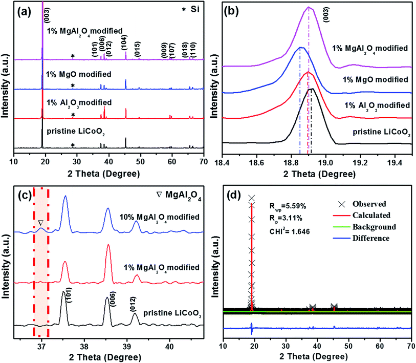
The XRD patterns of the pristine LiCoO2 and the modified LiCoO2 samples are shown in Fig. 1. From Fig. 1a, all the strong diffraction peaks except the peak at 28.5° (from the internal standard Si) can be indexed to the hexagonal phase with space group R![[3 with combining macron]](https://www.rsc.org/images/entities/char_0033_0304.gif) m (JPCDS card no. 50-0653). No diffraction peak corresponding to Al2O3, MgO and MgAl2O4 can be clearly observed in the modified samples owing to their low content of 1%. Even though all the 1% Al2O3, MgO and MgAl2O4 modifications do not greatly affect the crystal structure of LiCoO2, the (003) peak at around 19° displays a distinct shift in every modified LiCoO2 sample in Fig. 1b. The left shift to a smaller degree means the increase of the lattice parameters and the swelling of the lattice volume, which is in agreement with the previous literatures.7,8 During high-temperature surface modification, Mg2+ and Al3+ cations could partially dope into the LiCoO2 lattice from the modified layer.24 Since the ionic size of Al3+ (0.535 Å) is smaller than that of Mg2+ (0.720 Å), Al3+ diffuses into the LiCoO2 lattice more easily than Mg2+. That is the reason for the order of the (003) peak position: MgO modification < MgAl2O4 modification < Al2O3 modification. This is also consistence with mostly recent viewpoint that modification species can be incorporated at grain boundaries into the LiCoO2 surface and lead to reversible structural changes.14 In order to confirm the formation of spinel MgAl2O4, Fig. 1c shows the magnified XRD patterns of the 10 wt% MgAl2O4-modified LiCoO2 sample compared with the pristine and the 1 wt% MgAl2O4-modified LiCoO2. The full-range XRD patterns can be found in ESI (Fig. S1†), which shows that no peak of MgAl2O4 is observed due to the low quantity unless the amount increases to 10 wt%. From the magnified XRD patterns in Fig. 1c, the existence of spinel MgAl2O4 is confirmed by the peak at 37°,21 which corresponds to the (311) plane of MgAl2O4 lattice. The Rietveld refinement patterns of the 1% MgAl2O4-modified LiCoO2 shown in Fig. 1d further prove the existence of spinel MgAl2O4 in the 1% MgAl2O4-modified LiCoO2 and the real content of spinel MgAl2O4 is about 0.6%.
m (JPCDS card no. 50-0653). No diffraction peak corresponding to Al2O3, MgO and MgAl2O4 can be clearly observed in the modified samples owing to their low content of 1%. Even though all the 1% Al2O3, MgO and MgAl2O4 modifications do not greatly affect the crystal structure of LiCoO2, the (003) peak at around 19° displays a distinct shift in every modified LiCoO2 sample in Fig. 1b. The left shift to a smaller degree means the increase of the lattice parameters and the swelling of the lattice volume, which is in agreement with the previous literatures.7,8 During high-temperature surface modification, Mg2+ and Al3+ cations could partially dope into the LiCoO2 lattice from the modified layer.24 Since the ionic size of Al3+ (0.535 Å) is smaller than that of Mg2+ (0.720 Å), Al3+ diffuses into the LiCoO2 lattice more easily than Mg2+. That is the reason for the order of the (003) peak position: MgO modification < MgAl2O4 modification < Al2O3 modification. This is also consistence with mostly recent viewpoint that modification species can be incorporated at grain boundaries into the LiCoO2 surface and lead to reversible structural changes.14 In order to confirm the formation of spinel MgAl2O4, Fig. 1c shows the magnified XRD patterns of the 10 wt% MgAl2O4-modified LiCoO2 sample compared with the pristine and the 1 wt% MgAl2O4-modified LiCoO2. The full-range XRD patterns can be found in ESI (Fig. S1†), which shows that no peak of MgAl2O4 is observed due to the low quantity unless the amount increases to 10 wt%. From the magnified XRD patterns in Fig. 1c, the existence of spinel MgAl2O4 is confirmed by the peak at 37°,21 which corresponds to the (311) plane of MgAl2O4 lattice. The Rietveld refinement patterns of the 1% MgAl2O4-modified LiCoO2 shown in Fig. 1d further prove the existence of spinel MgAl2O4 in the 1% MgAl2O4-modified LiCoO2 and the real content of spinel MgAl2O4 is about 0.6%.
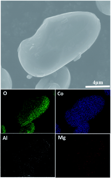
Fig. 2 shows SEM images of the pristine LiCoO2 and 1 wt% Al2O3, MgO, MgAl2O4-modified LiCoO2 samples. The surface of the pristine LiCoO2 (Fig. 2a) is quite smooth and clean, but some stuff can be found on the surfaces of the Al2O3, MgO, MgAl2O4-modified LiCoO2 particles shown in Fig. 2b–d. Quite different from the loose connection between the modified MgO and the LiCoO2 particle (Fig. 2c), the tight connections between the modified Al2O3 or MgAl2O4 with the LiCoO2 particle are shown clearly in Fig. 2b and d. Since Al3+ ion (0.535 Å) has the smaller size than Mg2+ ion (0.720 Å), it is reasonable for more Al3+ diffusion from Al2O3 and MgAl2O4 into the LiCoO2 lattice than Mg2+ from MgO during the high-temperature treatment, which enhances the connection between the modified material and the LiCoO2 bulk. The tight connection between the modified material and the LiCoO2 bulk means a pretty stable and conformal surface modification. It is indicative of that the Al2O3 and MgAl2O4 modifications have the higher coverage ratios than the MgO modification, and thus more effectively suppress the structural collapse of LiCoO2 and interfacial side reactions between the charged cathode and the electrolyte. In order to check the uniformity of the MgAl2O4 modification layer, EDS mapping was further performed and the results are shown in Fig. 3. It is clearly shown that the elements O, Al and Mg are uniformly dispersed on the surface of the MgAl2O4-modified LiCoO2. That means the elements Mg and Al in the MgAl2O4-modified LiCoO2 sample are uniformly distributed, illustrating that the MgAl2O4 modification is quite uniform and conformal.
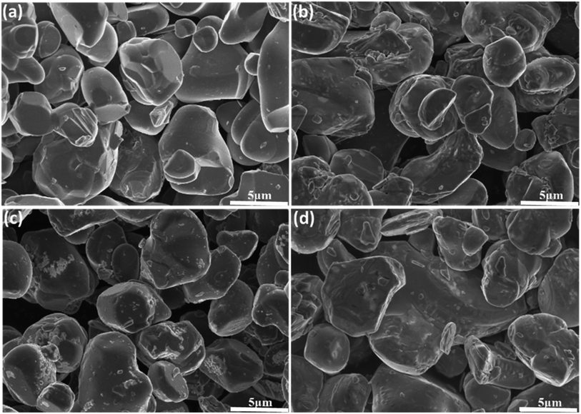 | ||
| Fig. 2 SEM images of (a) the pristine LiCoO2; (b) Al2O3-modified LiCoO2; (c) MgO-modified LiCoO2; (d) and MgAl2O4-modified LiCoO2 at high magnification (×5.0k). | ||
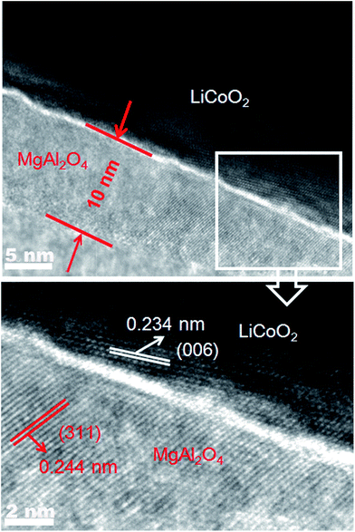
In order to observe the thickness of the surface modification layer in the MgAl2O4-modified LiCoO2, Fig. 4 shows the HRTEM images of a MgAl2O4-modified LiCoO2 particle. The modification layer (translucent) has the thickness of around 10 nm and the lattice fringe of ca. 0.244 nm is consistent with the interplanar distance of (311) planes of spinel MgAl2O4. The dark region shows the (006) planes of layered LiCoO2 crystal with the fringe of ca. 0.234 nm. Fig. 4 also clearly shows that the modification layer is tightly attached on the surface of LiCoO2, which is beneficial to adequately suppress the interfacial side reactions between the charged LiCoO2 and the electrolyte.
The oxidation states of the Co and O elements in the pristine LiCoO2 and three modified LiCoO2 samples were investigated by XPS as shown in Fig. 5. The Co 2p peaks for the pristine and modified LiCoO2 shown in Fig. 5a included a 2p1/2 peak at around 780 eV and a 2p3/2 peak at around 795 eV.2 The modified LiCoO2 samples show a shift in the Co 2p1/2 peak by 0.1–0.3 eV toward a higher binding energy than the pristine, which indicates that the Co bonding environment in the surface of the modified samples has a small change.7 Similar change can also be found in O 1s peaks as shown in Fig. 5b. The O 1s peak at 529.3 eV is assigned to O2− ions in the O3 layered structure of LiCoO2, and the higher binding energy for the O 1s peak in the modified LiCoO2 samples is attributed to the Al/Mg substitution in Co site on the particle surface.2 The O 1s peak at 531.3 eV is difficult to be speculated but should be due to the free oxygen/adsorbed oxygen.25 In the modified LiCoO2 samples, the MgAl2O4 modification reveals the slight differences on both the Co 2p and O 1s peaks from the Al2O3 modification and MgO modification. More interestingly, the lower intensities for the Co 2p peak and the O 1s peak at 531.3 eV for the MgAl2O4 modified LiCoO2 suggest that the MgAl2O4 modification is more uniform than the MgO modification, which is accordance with the SEM results shown in Fig. 2. Fig. 5c and d show the depth profiles of Al and Mg elements in the 1% MgAl2O4-modified LiCoO2. At an etch level of 0 nm, the peak at 73 eV in Fig. 5c is ascribed to the binding energy of Al 2p.5 The intensity of the Al 2p peak greatly decreases at the level of 10 nm and that peak completely disappeared at the level of 50 nm, which indicates that Al is just present on the surface region of the MgAl2O4 modified LiCoO2. Similarly as the depth profiles of Al 2p, the intensity of the Mg 2p peak at 49 eV in Fig. 5d26 drops obviously from the etch level of 0 nm to 10 nm.
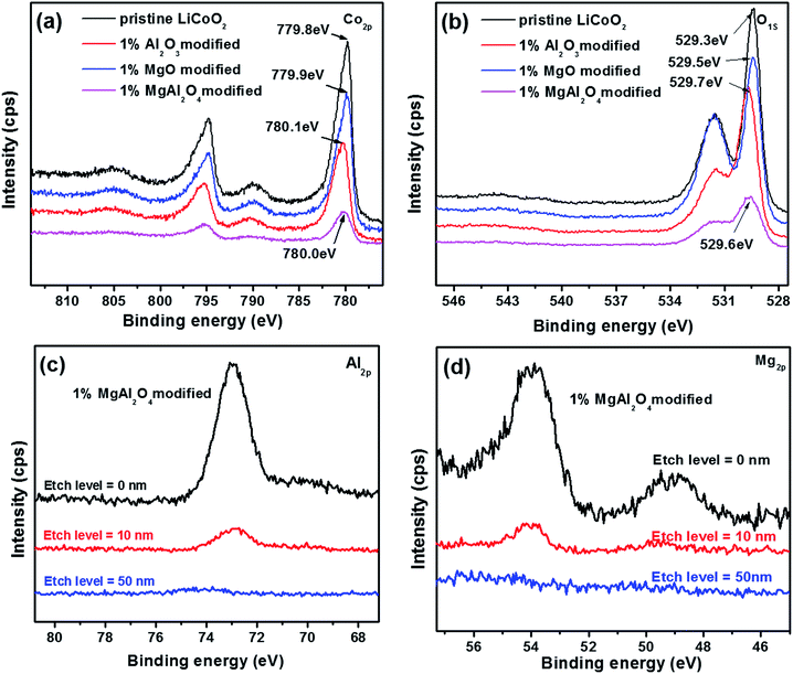 | ||
| Fig. 5 XPS spectra (a, b) of the pristine LiCoO2 and Al2O3, MgO, MgAl2O4-modified LiCoO2 samples, and the depth profiles of Al (c) and Mg (d) elements in the 1% MgAl2O4-modified LiCoO2. | ||
Electrochemical properties
Electrochemical properties of the pristine LiCoO2 and Al2O3, MgO, MgAl2O4-modified LiCoO2 were evaluated in the Li|| LiCoO2 coin-cells. Fig. 6 shows initial, 10th, 40th and 70th charge–discharge curves of the pristine LiCoO2 and Al2O3, MgO, MgAl2O4-modified LiCoO2 cells between 3.0 and 4.5 V, respectively. From the initial voltage profiles in Fig. 6a, the pristine and MgO-modified LiCoO2 display slightly higher discharge capacity than the Al2O3 and the MgAl2O4 modified LiCoO2. Moreover, the latter two have higher charge voltage plateau, especially for the Al2O3-modified sample, which corresponds to the high electrochemical polarization. Cyclic voltammograms (CVs) results also clearly indicate that the Al2O3 and the MgAl2O4 modified LiCoO2 samples exhibit higher electrochemical polarization in ESI (Fig. S2†). At the 10th cycle (Fig. 6b), the MgO and MgAl2O4-modified LiCoO2 samples deliver the higher discharge capacities than the pristine and the Al2O3-modified LiCoO2 samples. However, the pristine LiCoO2 shows both fast capacity fading and voltage fading at the 40th cycle (Fig. 6c), which is just similar as previous literatures.3,6,27 Different from the Al2O3 and MgAl2O4-modified LiCoO2, the MgO-modified LiCoO2 experiences a visible capacity fading from 180 mA h g−1 at the 10th cycle to 160 mA h g−1 at the 40th cycle. Furthermore, at the 70th cycle shown in Fig. 6d, the MgO-modified LiCoO2 exhibits a serious capacity fading to 120 mA h g−1, along with a big voltage plateau drop. The MgAl2O4-modified LiCoO2 shows higher capacity than the others at the 70th cycle. The cycling performance of the pristine LiCoO2 and Al2O3, MgO, MgAl2O4-modified LiCoO2 was shown in Fig. 7. Clearly, the discharge capacity of the pristine LiCoO2 drops to 72 mA h g−1 after 70 cycles, with the capacity retention of 42% (vs. the capacity of the 3rd cycle). Although the MgO-modified LiCoO2 has the higher discharge capacity at the first twenty cycles than the others, a fast capacity fading leads to the capacity of only 115 mA h g−1 after 70 cycles with the capacity retention of 63%. Herein, the MgO modification can improve the capacity but has invisible effect on enhancing the cycling stability, which is in accordance with the Shim's result.8 However, both the Al2O3 and MgAl2O4-modified LiCoO2 samples show the excellent cycling stability with the capacity retention over 96% after 70 cycles. Especially, the MgAl2O4-modified LiCoO2 has not only the excellent cycling stability and also the highest capacity. The enhanced electrochemical performance of the MgAl2O4-modified LiCoO2 is mainly attributed to both the uniform modification layer (Fig. 2d) and Mg2+/Al3+ dopings on the surface of LiCoO2 particles (Fig. 1b). The uniform MgAl2O4 layer can effectively prevent the oxidation decomposition of the electrolyte and Co4+ dissolution into the electrolyte at high voltages.6,8 These results clearly indicate that the MgAl2O4 modification exhibits the combined advantages of the Al2O3 modification on cycling stability and the MgO modification on capacity improvement. In addition, in our study the 1% MgAl2O4 modification is better than 0.5% and 2% modification (Fig. S3 in ESI†). The optimal composition of MgAl2O4 means the appropriate thickness of the modification layer. It is vital to not only provide vigorous protection for LiCoO2 from the electrolyte corrosion (resulting in Co4+ dissolution), but also allow Li+ ion transport fluently (lower impedance).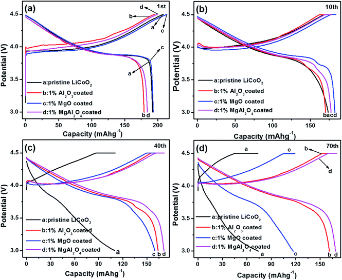 | ||
| Fig. 6 Charge and discharge curves of the pristine LiCoO2 and Al2O3, MgO, MgAl2O4-modified LiCoO2 at (a) the first cycle; (b) the 10th cycle; (c) the 40th cycle and (d) the 70th cycle. | ||
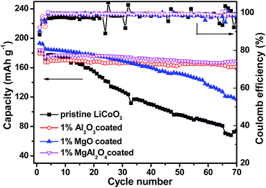 | ||
| Fig. 7 Cycling performance at the current rate of 1C and coulombic efficiency of the pristine LiCoO2 and Al2O3, MgO, MgAl2O4-modified LiCoO2. | ||
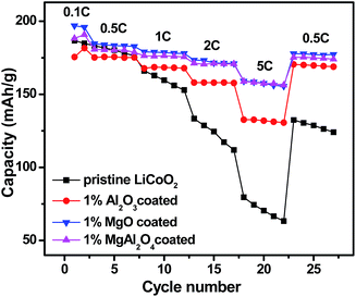
Fig. 8 shows rate capabilities of the pristine LiCoO2 and Al2O3, MgO, MgAl2O4-modified LiCoO2 samples between 3.0 and 4.5 V. After two formation cycles at 0.1C, all the cells were charged at a rate of 0.5C and discharged at incremental rates from 0.5 to 5C followed by recovering back to 0.5C. In the case of the pristine LiCoO2, its discharge capacity rapidly drops with increasing the current rates and even at the same rate the capacity fades fast, just similar as the cycling performance shown in Fig. 7. The three modified LiCoO2 samples exhibit the enhanced rate capability, presumably due to the positive effect of Mg2+/Al3+ surface dopings on increasing ionic conductivity. The Al2O3-modified LiCoO2 delivers the capacities of 168 mA h g−1 at 1C, 157 mA h g−1 at 2C and 133 mA h g−1 at 5C. Similar as their higher capacities shown in Fig. 7, the MgO and MgAl2O4-modified LiCoO2 samples show higher rate capabilities than the Al2O3-modified LiCoO2. Both the MgO and MgAl2O4-modified LiCoO2 samples deliver the capacity of 158 mA h g−1 at 5C. In addition, when the current rate returns back to 0.5C, the discharge capacities of all the modified samples can be restored. The enhanced rate capability of the MgAl2O4-modified LiCoO2 is possibly due to high Li+ ion conductivity of the MgAl2O4 layer.
To further understand the effect of the MgAl2O4 modification on the electrochemical performance of LiCoO2, EIS results of the Li||LiCoO2 cells using the pristine LiCoO2 and Al2O3, MgO, MgAl2O4-modified LiCoO2 materials are compared in Fig. 9. The Nyquist plots of the cells after 2 cycles (Fig. 9a) and 70 cycles (Fig. 9b) are composed of two semicircles in the high-to-medium frequency range and an inclined line in the low frequency range, similar as previously reported.11,13,28–30 The inset equivalent circuit in Fig. 9a is used to fit the Nyquist plots. The semicircle in the high frequency range (>20 Hz) can reflect the impedance (Rsf) for Li+ ion migration through the solid-electrolyte interphase (SEI) films which occur both on the cathode and Li anode,31,32 where the frequencies are shown as labelled. Considering that the same electrolyte and highly-purity Li metal were used, the differences on the SEI film impedances are attributed to the different LiCoO2 cathodes. The semicircle in the medium frequency range and the inclined line represent the charge transfer impedance (Rct) and the Warburg impedance (W), respectively. In Fig. 9a, the Al2O3-modified LiCoO2 exhibits the higher interface impedance than the pristine LiCoO2, which is consistent with previous literatures.6 However, both the MgO and MgAl2O4-modified LiCoO2 samples have the slightly smaller interface impedance than the pristine LiCoO2. The difference on the interface impedances is one of the main reasons for the difference on the capacity of the modified or unmodified LiCoO2 cathode materials, as proposed previously.3,29 After 70 cycles (Fig. 9b), the Al2O3 and MgAl2O4-modified LiCoO2 samples experience negligible increases on the interface impedance as well as the charge transfer impedance. These results strongly suggest that both the Al2O3 and MgAl2O4 modifications are so stable that the oxidation decomposition of the electrolyte on the charged LiCoO2 can be effectively suppressed and the structure of LiCoO2 bulk keeps stable. However, the MgO-modified LiCoO2 shows a distinct increase on interface impedance, even though its increase is not as rapid as that of the pristine LiCoO2. Moreover, the full plot parts of the pristine and the MgO-modified LiCoO2 samples in the inset of Fig. 9b (the region with low impedance values) mean much higher charge transfer impedances than the Al2O3 and MgAl2O4-modified LiCoO2 samples. That means the MgO surface modification could not essentially stabilize the surface structure of the LiCoO2 against the electrolyte at high-voltage cycling. Herein, the charge transfer impedances are not discussed. Nevertheless, the change on the interface impedances of various LiCoO2 samples are in consonance with their cycling stabilities shown in Fig. 7. In summary, the MgAl2O4 modification has the combined advantages on the high conductivity of the MgO modification and excellent stability of the Al2O3 modification.
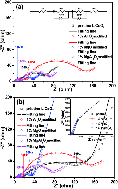 | ||
| Fig. 9 Electrochemical impedance spectra (EIS) of the pristine LiCoO2 and Al2O3, MgO, MgAl2O4-modified LiCoO2 at full discharge (a) after 2 cycles; (b) after 70 cycles. | ||
Conclusions
Spinel MgAl2O4 modification has been successfully carried out on the surface of LiCoO2 cathode material, and the modification layer is conformal and fairly uniform. The MgAl2O4 modification layer shows the positive effects of combining the Al2O3 modification on the cycling stability and the MgO modification on the conductivity. Therefore, the MgAl2O4-modified LiCoO2 exhibits excellent cycling stability and rate capability at high voltages up to 4.5 V. Such results indicate that the MgAl2O4 spinel is a good modification material for LiCoO2 cathode for high-voltage Li ion batteries.Acknowledgements
This study was supported by National Science Foundation of China (Grant No. 51372060 and 21676067) and the Opening Project of CAS Key Laboratory of Materials for Energy Conversion (KF2016005).Notes and references
- M. S. Whittingham, Chem. Rev., 2004, 104, 4271 CrossRef CAS PubMed.
- A. T. Appapillai, A. N. Mansour, J. Cho and S.-H. Yang, Chem. Mater., 2007, 19, 5748 CrossRef CAS.
- Y. Kim, G. M. Veith, J. Nanda, R. R. Unocic, M. F. Chi and N. J. Dudney, Electrochim. Acta, 2011, 56, 6573 CrossRef CAS.
- H. Miyashiro, Y. Kobayashi, S. Seki, Y. Mita, A. Usami, M. Nakayama and M. Wakihara, Chem. Mater., 2005, 17, 5603 CrossRef CAS.
- G. T. K. Fey, H. M. Kao, P. Muralidharan, T. P. Kumar and Y. D. Cho, J. Power Sources, 2006, 163, 135 CrossRef CAS.
- F. Zhao, Y. Tang, J. Wang, J. Tian, H. Ge and B. Wang, Electrochim. Acta, 2015, 174, 384 CrossRef CAS.
- M. Xie, T. Hu, L. Yang and Y. Zhou, RSC Adv., 2016, 6, 63250 RSC.
- J.-H. Shim, S. Lee and S. S. Park, Chem. Mater., 2014, 26, 2537 CrossRef CAS.
- Y. Iriyam, H. Kurita, I. Yamada, T. Abe and Z. Ogumi, J. Power Sources, 2004, 137, 111 CrossRef.
- G. Q. Liu, H. T. Kuo, R. S. Liu, C. H. Shen, D. S. Shy, X. K. Xing and J. M. Chen, J. Alloys Compd., 2010, 496, 512 CrossRef CAS.
- B. J. Hwang, C. Y. Chen, M. Y. Cheng, R. Santhanam and K. Ragavendran, J. Power Sources, 2010, 195, 4255 CrossRef CAS.
- J. Cho, C. Kim and S. I. Yoo, Electrochem. Solid-State Lett., 2000, 3, 362 CrossRef CAS.
- J. Cho, Y. J. Kim and B. Park, Angew. Chem., Int. Ed., 2001, 40, 3367 CrossRef CAS PubMed.
- S. Taminato, M. Hirayama, K. Suzuki, K. Tamura, T. Minato, H. Arai, Y. Uchimoto, Z. Ogumi and R. Kanno, J. Power Sources, 2016, 307, 599 CrossRef CAS.
- D. Takamatsu, S. Mori, Y. Orikasa, T. Nakatsutsumi, Y. Koyama, H. Tanida, H. Arai, Y. Uchimoto and Z. Ogumi, J. Electrochem. Soc., 2013, 160(5), A3054 CrossRef CAS.
- L. L. Zhang, J. J. Chen, S. Cheng and H. F. Xiang, Ceram. Int., 2016, 42, 1870 CrossRef CAS.
- A. Zhou, J. Xu, X. Dai, B. Yang, Y. Lu, L. Wang, C. Fan and J. Li, J. Power Sources, 2016, 322, 10 CrossRef CAS.
- X. Pu and C. Yu, Nanoscale, 2012, 4, 6743 RSC.
- M. J. Mees, G. Pourtois, F. Rosciano, B. Put, P. M. Vereecken and A. Stesmans, Phys. Chem. Chem. Phys., 2014, 16, 5399 RSC.
- R. Djenadic, M. Botros and H. Hahn, Solid State Ionics, 2016, 287, 71 CrossRef CAS.
- N. Angulakshmi, K. S. Nahm, J. R. Nair, C. Gerbaldi, R. Bongiovanni and N. Penazzi, Electrochim. Acta, 2013, 90, 179 CrossRef CAS.
- N. Ozawa, K. Donoue and T. Yao, Electrochem. Solid-State Lett., 2003, 6, A106 CrossRef CAS.
- G. T. K. Fey, Z.-F. Wang, C.-Z. Lu and T. P. Kumar, J. Power Sources, 2005, 146, 245 CrossRef CAS.
- C. Li, H. P. Zhang, L. J. Fu, H. Liu, Y. P. Wu, E. Rahm, R. Holze and H. Q. Wu, Electrochim. Acta, 2006, 51, 3872 CrossRef CAS.
- G. Chen, H. Geng, Z. Wang, R. Yang and Y. Xu, Ionics, 2016, 22, 629 CrossRef CAS.
- S. J. Shi, J. P. Tu, Y. Y. Tang, X. Y. Liu, Y. Q. Zhang, X. L. Wang and C. D. Gu, Electrochim. Acta, 2013, 88, 671 CrossRef CAS.
- K. C. Kim, J.-P. Jegal, S.-M. Bak, K. C. Roh and K.-B. Kim, Electrochem. Commun., 2014, 43, 113 CrossRef CAS.
- G. R. Hu, J. C. Cao, Z. D. Peng, Y. B. Cao and K. Du, Electrochim. Acta, 2014, 149, 49 CrossRef CAS.
- B. Wu, Y. Ren, D. Mu, X. Liu, G. Yang and F. Wu, RSC Adv., 2014, 4, 10196 RSC.
- J. Zhang, Y. J. Xiang, Y. Yu, S. Xie, G. S. Jiang and C. H. Chen, J. Power Sources, 2004, 132, 187 CrossRef CAS.
- C. H. Chen, J. Liu and K. Amine, J. Power Sources, 2001, 96, 321–328 CrossRef CAS.
- A. Sakuda, A. Hayashi and M. Tatsumisago, J. Power Sources, 2010, 195, 599 CrossRef CAS.
Footnote |
| † Electronic supplementary information (ESI) available. See DOI: 10.1039/c6ra27463c |
| This journal is © The Royal Society of Chemistry 2017 |

