 Open Access Article
Creative Commons Attribution 3.0 Unported Licence
Graphene/polyaniline@carbon cloth composite as a high-performance flexible supercapacitor electrode prepared by a one-step electrochemical co-deposition method†
Lele
Wen
a,
Ke
Li
b,
Jingjing
Liu
b,
Yanshan
Huang
b,
Fanxing
Bu
b,
Bin
Zhao
*a and
Yuxi
Xu
 *b
*b
aDepartment of Material Science and Engineering, University of Shanghai for Science and Technology, Shanghai 200093, China. E-mail: zhaobin@usst.edu.cn
bState Key Laboratory of Molecular Engineering of Polymers, Department of Macromolecular Science, Fudan University, Shanghai 200433, China. E-mail: xuyuxi@fudan.edu.cn
First published on 23rd January 2017
Abstract
Increasing numbers of flexible universal energy storage devices are required for wearable and portable products. A typical representation of energy storage devices are supercapacitors. However, their applications are greatly limited due to their low conductivity, which is strongly restricted by the effect of the binder. We designed and prepared a flexible and binder-free supercapacitor based on a graphene–polyaniline@carbon cloth composite by a one-step electrochemical co-deposition process. The composite exhibited excellent electrochemical performance with a high specific capacitance of 793 F g−1 at a current density of 0.5 A g−1 and favorable cycle stability (retention of 81% of initial specific capacitance after 10![[thin space (1/6-em)]](https://www.rsc.org/images/entities/char_2009.gif) 000 cycles). The flexible symmetric device also showed satisfactory specific capacitance of 512 F g−1 at a current density of 0.5 A g−1, desirable cycling stability (retention of 85% specific capacitance over 10
000 cycles). The flexible symmetric device also showed satisfactory specific capacitance of 512 F g−1 at a current density of 0.5 A g−1, desirable cycling stability (retention of 85% specific capacitance over 10![[thin space (1/6-em)]](https://www.rsc.org/images/entities/char_2009.gif) 000 cycles) and considerable energy density of 11.38 W h kg−1 at a power density of 199.80 W kg−1. We believe that this flexible and binder-free supercapacitor with excellent electrochemical properties will meet the demands in roll-up displays, electronic paper and wearable electronic products.
000 cycles) and considerable energy density of 11.38 W h kg−1 at a power density of 199.80 W kg−1. We believe that this flexible and binder-free supercapacitor with excellent electrochemical properties will meet the demands in roll-up displays, electronic paper and wearable electronic products.
1. Introduction
Due to rapid technological developments, there has been a huge demand for universal flexible energy storage devices because of their extraordinary potential application in wearable and portable electronic products such as roll-up displays, electronic paper, and wearable systems for personal multimedia.1,2 Flexible supercapacitors (SCs) are a typical representation of flexible energy storage devices. They can meet the needs of flexible energy storage due to their high power density, high operational safety, fast charge/discharge capacity, excellent cycle stability and acceptable energy density.3,4 The key components of a flexible SC are the electrodes, which make a significant contribution to the electrochemical performance of the device. Therefore, there is a huge requirement for designing and preparing electrode materials with high flexibility, moderate mechanical strength, large specific capacitance and excellent cycle stability. In recent years, plenty of works have concentrated on using various carbon-based materials such as carbon nanotubes,5,6 carbon anions,7 activated carbon,8 carbon fibers9 and graphene10 to fabricate SCs. Several studies have demonstrated that to construct SCs with high flexibility and excellent electrochemical properties not only requires constitutive materials to be equipped with high mechanical integrity and outstanding electrical performance, but also relies on their controlled assembly into functional devices.11–15Among various materials, pseudocapacitive materials such as conducting polymers and transition metal oxides exhibit great potential in flexible SCs electrodes because of their fast and reversible redox processes as well as excellent electrochemical behaviors. In particular, polyaniline (PANI), as one type of conducting polymer, has been intensely studied in recent years due to its ultrahigh theoretical capacitance, favorable environmental stability, controlled structure and morphology, special conducting mechanism and doping/dedoping chemistry.16 PANI has become one of the most promising candidates for energy storage device materials. However, the volumetric changes and mechanical degradation of PANI electrodes during charging/discharging processes result in poor cycling stability and rate capability, and hinder their practical applications severely.17,18 Furthermore, the low conductivity of neutral PANI also greatly impedes its electrochemical properties when it is used directly as electrode material in SCs. Introduction of carbon-based materials, for example, graphene hydrogel, into PANI, means that these electrode composite materials have greatly improved conductivity, higher specific capacitance and longer cycling life.19 However, it is necessary to add binders and conductive additives not only to improve the adhesion between electrode materials and substrates, but also to enhance the conductivity of the electrodes, which inevitably and severely reduces the electronic performance of these devices.20 Thus, two main problems must be solved to accelerate the development of flexible SCs: (i) search for electrode materials with high electrochemical performance; (ii) enhance the connection between electrodes with collectors to improve the conductivity of the device. Carbon cloth could be used as a conductive and flexible substrate material for flexible SCs electrodes due to its high conductivity, flexibility and fast electron/ion transport.
Herein, we successfully prepared a flexible, binder-free graphene/PANI electrode based on carbon cloth (GP@cc) by a simple one-step electrochemical co-deposition method. This electrode exhibited an impressive specific capacitance of 793 F g−1 at 0.5 A g−1 in 1 M H2SO4 aqueous electrolyte in a three-electrode system. Moreover, the GP@cc composite showed excellent rate capability and favorable cycling stability (retained 81% of initial specific capacitance after 10![[thin space (1/6-em)]](https://www.rsc.org/images/entities/char_2009.gif) 000 cycles at 5 A g−1). Carbon cloth could serve as collector due to its high conductivity and fast electron/ion transport. Thus, we directly used GP@cc composites as electrodes and collectors to fabricate a flexible symmetric SC using 1 M H2SO4 as electrolyte without adding any other binder or conductive additives. The integrated device not only showed extraordinary mechanical flexibility and high conductivity, it also exhibited the desired specific capacitance (512 F g−1 at 0.5 A g−1) and acceptable cycling stability (retained 85% of initial specific capacitance after 10
000 cycles at 5 A g−1). Carbon cloth could serve as collector due to its high conductivity and fast electron/ion transport. Thus, we directly used GP@cc composites as electrodes and collectors to fabricate a flexible symmetric SC using 1 M H2SO4 as electrolyte without adding any other binder or conductive additives. The integrated device not only showed extraordinary mechanical flexibility and high conductivity, it also exhibited the desired specific capacitance (512 F g−1 at 0.5 A g−1) and acceptable cycling stability (retained 85% of initial specific capacitance after 10![[thin space (1/6-em)]](https://www.rsc.org/images/entities/char_2009.gif) 000 cycles at 5 A g−1).
000 cycles at 5 A g−1).
2. Experimental section
2.1 Synthesis of graphene oxide (GO)
On the basis of the modified Hummers' method, GO was synthesized through the oxidation of natural graphite powder.21 The obtained GO dispersion was then centrifuged for 30 min at 4000 rpm to remove aggregates. Then, it was purified by dialysis for 1 week to remove remaining salts impurities. Finally, the resulting GO dispersion was adjusted to 0.36 mg mL−1 for subsequent experiments.2.2 Preparation of graphene/polyaniline composite
Carbon cloth (1 cm × 2 cm) was soaked in acetone and distilled water, sonicated for 30 min to remove grease and impurities on the surface. This procedure was repeated several times, respectively, and then the cloth was dried under vacuum at 60 °C. Then, 135 μL aniline was added to 10 mL distilled water, and sonicated at room temperature until the solution became transparent. The transparent solution mentioned above was added to 1 mL 1.0 M Na2SO4 in 15 mL GO dispersion, sonicated for 10 min, and the resulting mixed solution used as the electrolyte for electrochemical co-deposition. The latter was conducted in a three-electrode system (carbon cloth as the working electrode, platinum (Pt) foil as the counter electrode, and Ag/AgCl as the reference electrode) using cyclic voltammetry at a scan rate of 2 mV s−1 with a potential window from −1.2 to 0.8 V and with 20 cyclic voltammetry (CV) cycles. As a comparison, PANI@cc was prepared via cyclic voltammetry with a potential window from 0 to 0.8 V at 2 mV s−1; RGO@cc was also obtained by CV with a potential window from −1.2 to 0 V at 2 mV s−1. These samples were cleaned by distilled water and the procedure repeated several times to remove the absorbed monomer or remaining salts, and they were noted as RGO@cc, PANI@cc, and GP@cc, respectively.2.3 Device fabrication
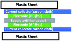
Two pieces of graphene/PANI@cc composites were soaked in 1.0 M H2SO4 aqueous electrolyte for 12 h with constant stirring. These were used as both electrodes of the flexible SC device, and were separated by filter paper also soaked with 1.0 M H2SO4 aqueous electrolyte. Carbon cloth was directly used as a current collector without any binders or other additives. Then, they were assembled into a layered structure by “sandwiching” the entire SC device between two plastic sheets using clips and sealed by parafilm for subsequent electrochemical tests. The structure of the flexible SC device is shown in Scheme 1.2.4 Characterization
The morphologies of RGO@cc, PANI@cc, and GP@cc were examined on a Zeiss Ultra 55 field emission scanning electron microscope. Raman spectra were collected on an XploRA laser Raman spectrometer using a 532 nm laser beam. X-ray photoelectron spectra (XPS) were recorded on PerkinElmer PHI 5300 using an Mg Kα source (1253.6 eV). XRD analyses were done with a Rigaku D/Max 2500 X-ray diffractometer with a Cu Kα radiation source (k = 1.54 Å).2.5 Electrochemical characterization and analyses
All electrochemical experiments were carried out using a CHI 760E electrochemical workstation (Shanghai CH Instrument Co., China). The electrochemical measurements of the device were conducted in a two-electrode system, whereas those for the graphene/PANI@cc electrode were performed in a three-electrode system in 1.0 M H2SO4 aqueous solution electrolyte at room temperature, with Pt and Ag/AgCl as counter and reference electrodes, respectively. The potential ranges of CV and galvanostatic charge/discharge (GCD) tests were 0.0 to 0.8 V, and the GP@cc was directly employed as the working electrode. Electrochemical impedance spectroscopy measurements were carried out at open circuit potential with a sinusoidal signal over a frequency range from 100 kHz to 0.01 Hz at an amplitude of 5 mV. The cycle life of the GP@cc electrode and the device were conducted by GCD measurements at a current density of 5 A g−1. The specific capacitances (Cwt) derived from galvanostatic charge curves were calculated based on the following formula: Cwt = IΔt/mΔV, where I is the constant discharge current, Δt is the time for full discharge, m is the mass of one electrode, and ΔV represents the voltage drop upon discharging (excluding the IR drop). In symmetric SCs, the specific capacitance (Csc) of the device was calculated according to Csc = 2Cwt. The energy density of the symmetric device was calculated based on the following formula: Ewt = CwtV2/8, where V is the operating voltage. Power densities (P) were calculated using the following formula: P = E/Δt, where Δt is the discharge time.3. Results and discussion
The graphene/PANI@cc composite was successfully prepared via a simple one-step electrochemical co-deposition method using GO and aniline mixed solution as the electrolyte in a three-electrode system. The mass transfer of GO from the bulk phase of the dispersed system to the surface of the electrode leads to the absorption of GO to the surface of the electrode. The high negative potential (<−0.75 V, vs. Ag/AgCl) can overcome the energy barriers for the reduction of oxygen functionalities (–OH, C–O–C on the plane and –COOH on the edge). Moreover, cathodic peak potentials of GO electro-reduction shift negatively as pH increased. Protonation in the electro-reduction process occurs and is facilitated at lower pH values. Thus, we could use the following equation to explain the reduction mechanism of GO during the deposition, indicating the important role of hydrogen ions in this process.22,23| GO + aH+ + be− → RGO + cH2O | (1) |
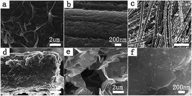
Therefore, the reduction of GO during the deposition could be achieved in various electrolytes, such as solutions of acid, alkali and saline. Carbon cloth was used as working electrode and served as a flexible and highly conductive substrate to synthesize graphene/PANI composites due to its favorable mechanical strength, excellent conductivity and high flexibility. Moreover, we could adjust the area of the carbon cloth to control the size of the graphene/PANI composite. A scanning electron micrograph of pure carbon cloth is shown in Fig. S1,† and reveals that carbon cloth was weaved by abundant carbon fibers and had a highly smooth surface. Fig. 1a–f illustrates the morphology and structure of the resultant RGO@cc, PANI@cc and GP@cc composites by scanning electron microscopy (SEM). Fig. 1a shows the well-defined and interconnected graphene framework completely coating the surface of the carbon cloth. Fig. 1b illustrates PANI also totally coating the surface of carbon cloth. Fig. 1c–f show SEM images of the GP@cc composite. From Fig. 1c we can see that graphene and PANI are distributed on the surface of carbon cloth uniformly. Fig. 1d clearly shows the surface of carbon cloth to be tightly coated by graphene nanosheets and that PANI nanowires are uniformly dispersed on graphene nanosheets. From Fig. 1e we can see more clearly that PANI nanowires are distributed on graphene nanosheets uniformly and connected to nearby carbon fibers with void spaces. Graphene nanosheets not only interconnected with each other to form a thin graphene layer but also interacted with PANI nanowires through the large surface of carbon cloth. Fig. 1f demonstrates the graphene nanosheets interconnected and formed 3D porous frameworks with pore sizes from sub-micrometers to several micrometers to facilitate fast access of ions to electrolytes.
To explore the interaction between graphene with PANI more clearly, Raman spectroscopy was performed. Fig. 2a illustrates the Raman spectra of RGO@cc, PANI@cc and GP@cc. There are two obvious peaks at 1349 and 1600 cm−1 in the spectrum of RGO@cc that correspond to the characteristic peaks of carbon materials, D and G bands, respectively.24,25 The Raman spectrum of PANI@cc displays the characteristic peaks of PANI. The 1599 cm−1 peak corresponds to the C–C stretching of benzenoid units, the Raman peaks at 1348 cm−1 and 1186 cm−1 are connected with radical cation C–N+ stretching and C–H in-plane bending, respectively. Compared with neat PANI@cc, the GP@cc composite shows an obvious difference in sharpness and intensities of peaks within low wave number regions. The peak at 412 cm−1 is related to the out-of-plane C–H wag. The peak corresponding to a phenazine-like segment appears at around 607 cm−1 and the peak around 813 cm−1 can be assigned to C–H deformation.26,27 According to the spectra of the GP@cc composite, we could confirm that doped PANI and reduced GO coexisted in the composite. Furthermore, Fig. 2b–d illustrates the XPS of the GP@cc composite in a wide scan. Fig. 2b reveals that the resultant graphene/PANI@cc composite was composed of the four elements C, N, O and S, confirming the existence of PANI and that PANI was doped by SO42−. Fig. 2c shows the XPS spectrum of the N 1s region. We could conclude that its existence mainly included three electronic states: the binding energy (BE) at around 399.4 eV related to the benzenoid amine; the BE at around 398.8 eV assigned to the quinoid amine; and the BE at around 401.4 eV associated with the nitrogen cationic radical (N+˙).28Fig. 2e presents the XPS spectrum of the C 1s region, which could be divided into four peaks with a BE of 284.5 eV (C–C/C![[double bond, length as m-dash]](https://www.rsc.org/images/entities/char_e001.gif) C), 285.6 eV (C–N), 286.6 eV (C–O/C
C), 285.6 eV (C–N), 286.6 eV (C–O/C![[double bond, length as m-dash]](https://www.rsc.org/images/entities/char_e001.gif) O), and 290.2 eV (O–C
O), and 290.2 eV (O–C![[double bond, length as m-dash]](https://www.rsc.org/images/entities/char_e001.gif) O), respectively.29 According to this spectrum, we could conclude that the oxygenic functional groups showed much weaker relative intensities than GO, indicating the high reduction of GO. The Raman spectra and XPS spectra results discussed above and XRD (shown in S2†) indicated that we prepared the graphene/PANI composite on the surface of carbon cloth successfully.30,31
O), respectively.29 According to this spectrum, we could conclude that the oxygenic functional groups showed much weaker relative intensities than GO, indicating the high reduction of GO. The Raman spectra and XPS spectra results discussed above and XRD (shown in S2†) indicated that we prepared the graphene/PANI composite on the surface of carbon cloth successfully.30,31
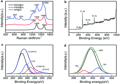 | ||
| Fig. 2 (a) Raman spectra of rGO@cc, PANI@cc and GP@cc; (b) XPS spectra of GP@cc; (c and d) C 1s (c) and N 1s (d) XPS spectra of GP@cc. | ||
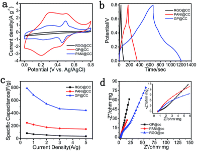
The electrochemical performances of the as-prepared GP@cc, RGO@cc and PANI@cc composites were compared with each other, as shown in Fig. 3. Fig. 3a illustrates the CV curves of the RGO@cc, PANI@cc and the GP@cc composites within a potential range from 0 to 0.8 V at a scan rate of 5 mV s−1. The specific capacitance of these samples could be represented by the area of closed CV curves. According to Fig. 3a, the GP@cc electrode showed much larger specific capacitance than those of RGO@cc and PANI@cc electrodes, which could be attributed to the favorable connection with each other leading to excellent conductivity. Fig. 2b shows the GCD tests within a potential range from 0 to 0.8 V at a current density of 0.5 A g−1, and indicated that the GP@cc electrode had the longest discharge time. The specific capacitances of RGO@cc, PANI@cc and GP@cc could be calculated from GCD curves. The specific capacitances of RGO@cc, PANI@cc and GP@cc were measured to be 86, 249 and 793 F g−1 at a current density of 0.5 A g−1, respectively, indicating that the GP@cc electrode provided much larger specific capacitance than those of RGO@cc and PANI@cc, which was consistent with the results of CV curves. Furthermore, we calculated the specific capacitances of the GP@cc, RGO@cc and PANI@cc electrodes at different current densities, as shown in Fig. 3c. The specific capacitances of the GP@cc electrode at various current densities were all much larger than those of the others. Moreover, the GP@cc electrode retained a specific capacitance of 444 F g−1 even though the current density increased to 5 A g−1. This result indicated its excellent rate capability, which was due to the high conductivity of carbon cloth and the excellent contact between carbon cloth, PANI and graphene. Electrochemical impedance spectroscopy is a very useful approach to evaluate various kinds of resistance during charge/discharge. Fig. 3d shows the Nyquist plots of RGO@cc, PANI@cc and GP@cc electrodes within the frequency range from 100 kHz to 0.05 Hz. In general, a Nyquist plot is composed of a semicircle in a high-frequency region corresponding to charge transfer resistance (Rct) and a straight line in a low-frequency region associated with capacitive behavior.32 The points extrapolating the straight line to intersect Z′ axes are assigned to electrolyte solution resistance, intrinsic resistance of active materials, and the interfacial contact resistance between active materials and the current collector.33–35 According to the magnified plots (inset of Fig. 3d), the point of GP@cc was much nearer −Z′′ axes than those of RGO@cc and PANI@cc, indicating the excellent contact between RGO, PANI and carbon cloth. Furthermore, Rct of GP@cc corresponding to the diameter of an inconspicuous loop was much smaller than that of RGO@cc and PANI@cc, indicating that the synergistic effect of RGO and PANI improved the conductivity of GP@cc. Moreover, the slope of the low-frequency region for GP@cc was much larger than those of RGO@cc and PANI@cc, suggesting faster ion diffusion of the electrolyte. On the basis of the results discussed above, we can conclude that the GP@cc electrode had much larger conductivity and better ion diffusion behavior than those of RGO@cc and PANI@cc, leading to its excellent electrochemical performances.
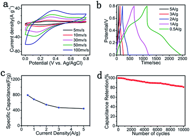
To further study the advantage of the flexible and binder-free GP@cc electrode for SC application, we used the GP@cc composite as the working electrode directly in a three-electrode system to evaluate its electrochemical properties. Fig. 4a shows the CV curves of the GP@cc electrode, which exhibited nearly rectangular shapes at scan rates from 5 to 200 mV s−1, which indicated that GP@cc possessed low resistance and ideal supercapacitive properties. In addition, the transition of PANI leads to the appearance of two redox peaks in CV curves.36 The CV curves of RGO@cc and PANI@cc at various scan rates are shown in Fig. S3 and S4,† respectively. Fig. 4b displays the GCD curves of the GP@cc electrode at different current densities. The GCD curves of rGO@cc and PANI@cc are shown in Fig. S5 and S6,† respectively. The discharge curves are nearly symmetrical to the relative charge curves, indicating the well-deserved combination between pseudocapacitive properties with a double-layer contribution. The specific capacitances of the GP@cc electrode at different current densities were calculated from the GCD curves, as shown in Fig. 4c. The specific capacitance of GP@cc was as high as 793 F g−1 at a current density of 0.5 A g−1, which is much larger than those of other graphene/PANI composites reported previously.30,37–42 Moreover, about 56% of capacitance was retained as the current density increased to 5 A g−1, indicating its favorable rate capacity. In addition, the cycle life is a significant factor of SCs for practical applications. The cycle life of the GP@cc electrode was measured by repeated GCD tests in a voltage range from 0 to 0.8 V at a current density of 5 A g−1. The results are displayed in Fig. 4d. Its specific capacitance retained about 81% after 10![[thin space (1/6-em)]](https://www.rsc.org/images/entities/char_2009.gif) 000 cycles, which indicated that the GP@cc electrode exhibited excellent cycling stability. The remarkably improved electrochemical performance originates in the special electrode design, which avoids the use of binders and other conductive additives, thus enhancing the contact between graphene, carbon cloth and PANI. In addition, the use of carbon cloth greatly improves the conductivity of the composite.
000 cycles, which indicated that the GP@cc electrode exhibited excellent cycling stability. The remarkably improved electrochemical performance originates in the special electrode design, which avoids the use of binders and other conductive additives, thus enhancing the contact between graphene, carbon cloth and PANI. In addition, the use of carbon cloth greatly improves the conductivity of the composite.
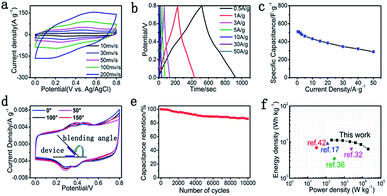
The flexible and binder-free symmetric SC device was fabricated using two pieces of GP@cc composites with 1.0 M H2SO4 as the electrolyte, and a digital picture of the flexible symmetric SC device is shown in Fig. S7.† The CV curves for a single symmetric device maintained the quasi-rectangular shape at various scan rates from 10 to 500 mV s−1, as shown in Fig. 5a. The GCD curves of the device shown in Fig. 5b display a straight line and symmetric shape within a potential window from 0 to 0.8 V at different current densities from 0.5 to 50 A g−1. These characteristics suggest the ideal capacitance of the symmetric device. According to Fig. 5c, the specific capacitance of the symmetric device achieved 512 F g−1 at a current density of 0.5 A g−1. Moreover, the device still retained 56.3% of the initial specific capacitance as the current density increased to 50 A g−1, indicating its favorable rate capacity. Furthermore, the GP@cc-based flexible symmetrical SC also showed high flexibility in bending measurements. Fig. 5d illustrates the CV curves of the device at different bending angles. The CV curve of the device showed little change even as the bending angle increased to 150°, indicating that the flexible SC based on GP@cc composite exhibited extraordinary flexibility and favorable mechanical properties even in a highly bent state. Fig. 5e illustrates the cycling behavior of the symmetric device at a current density of 5 A g−1. The symmetric device still retained about 85% of the initial specific capacitance after 10![[thin space (1/6-em)]](https://www.rsc.org/images/entities/char_2009.gif) 000 cycles, indicating its excellent cycle stability. This can be ascribed to the unique electrode design of the flexible, binder-free GP@cc composite. Fig. 5f is a Ragone diagram of the symmetric device. The energy and power densities of the symmetric device were calculated from the GCD curves. According to Fig. 5f, the symmetric device exhibited a maximum energy density of 11.38 W h kg−1 at a power density of 199.80 W kg−1, and a maximum power density of 20
000 cycles, indicating its excellent cycle stability. This can be ascribed to the unique electrode design of the flexible, binder-free GP@cc composite. Fig. 5f is a Ragone diagram of the symmetric device. The energy and power densities of the symmetric device were calculated from the GCD curves. According to Fig. 5f, the symmetric device exhibited a maximum energy density of 11.38 W h kg−1 at a power density of 199.80 W kg−1, and a maximum power density of 20![[thin space (1/6-em)]](https://www.rsc.org/images/entities/char_2009.gif) 000 W kg−1 at an energy density of 6.4 W h kg−1 at an open-circuit voltage of 0.8 V. This work shows a higher energy density than those of devices reported previously,17,32,36,42 which can be attributed to the synergistic effect of all components in GP@cc composite materials.
000 W kg−1 at an energy density of 6.4 W h kg−1 at an open-circuit voltage of 0.8 V. This work shows a higher energy density than those of devices reported previously,17,32,36,42 which can be attributed to the synergistic effect of all components in GP@cc composite materials.
4. Conclusions
We successfully prepared a flexible and binder-free GP@cc composite using a facile and scaled-up one-step electrochemical co-deposition method, and studied its practical application in a flexible symmetric SC. Owing to the synergistic effects of different components in the GP@cc composite material and the high flexibility and excellent conductivity of carbon cloth, the symmetric SC device based on a flexible, binder-free GP@cc electrode exhibited acceptable energy density, remarkable flexibility and excellent cycle stability. These features endow its great potential to be applied in smart, wearable and portable electronic products.Acknowledgements
This work was supported by the Program for Professor of Special Appointment (Eastern Scholar) at Shanghai Institutions of Higher Learning (No. TP2015002), and the National Natural Science Foundation of China (51673042).Notes and references
- J. M. Tarascon and M. Armand, Nature, 2001, 414, 359 CrossRef CAS.
- F. Beguin, K. Szostak, G. Lota and E. Frackowiak, Adv. Mater., 2005, 17, 2380 CrossRef CAS.
- Y. Xu, Z. Lin, X. Huang, Y. Wang, Y. Huang and X. Duan, Adv. Mater., 2013, 25, 5779 CrossRef CAS.
- P. Simon and Y. Gogotsi, Nat. Mater., 2008, 7, 845 CrossRef CAS.
- M. Kaempgen, C. K. Chan, J. Ma and Y. Cui, Nano Lett., 2009, 9, 1872–1876 CrossRef CAS.
- H. Chen, Y. Li, Y. Feng, P. Lv, P. Zhang and W. Feng, Electrochim. Acta, 2012, 60, 449–455 CrossRef CAS.
- D. Pech, M. Brunet, H. Durou, P. Huang, V. Mochalin, Y. Gogotsi, P. L. Taberna and P. Simon, Nat. Nanotechnol., 2010, 5, 651–654 CrossRef CAS.
- F. C. Wu, R. L. Tseng, C. C. Hu and C. C. Wang, J. Power Sources, 2004, 138, 351–359 CrossRef CAS.
- C. Kim, Y. O. Choi, W. J. Lee and K. S. Yang, Electrochim. Acta, 2004, 50, 883–887 CrossRef CAS.
- L. L. Zhang and X. S. Zhao, Chem. Soc. Rev., 2009, 38, 2520–2531 RSC.
- K. Wang, W. Zou, B. Quan, A. Yu, H. Wu, P. Jiang and Z. Wei, Adv. Energy Mater., 2011, 1, 1068–1072 CrossRef CAS.
- X. Xiao, T. Li, P. Yang, Y. Gao, H. Jin and W. Ni, ACS Nano, 2012, 6, 9200–9206 CrossRef CAS.
- B. G. Choi, S. J. Chang and H. W. Kang, Nanoscale, 2012, 4, 4983–4988 RSC.
- Y. J. Kang, S. J. Chun, S. S. Lee and B. Y. Kim, ACS Nano, 2012, 6, 6400–6406 CrossRef CAS PubMed.
- B. G. Choi, J. Hong, W. H. Hong, P. T. Hammond and H. Park, ACS Nano, 2011, 5, 7205–7213 CrossRef CAS.
- D. Tobjork and R. Osterbacka, Adv. Mater., 2011, 23, 1935–1961 CrossRef.
- Y. F. Wang, X. W. Yang, L. Qiu and D. Li, Energy Environ. Sci., 2013, 6, 477–481 RSC.
- Q. Q. Zhang, Y. Li, Y. Y. Feng and W. Feng, Electrochim. Acta, 2013, 90, 95–100 CrossRef CAS.
- Q. Wu, Y. X. Xu, Z. Y. Zhao, A. R. Liu and G. Q. Shi, ACS Nano, 2009, 3, 1745–1752 CrossRef.
- H. Y. Yu, J. H. Wu, L. Q. Fan, K. Q. Xu, X. Zhong, Y. Z. Lin and J. M. Lin, Electrochim. Acta, 2011, 56, 6881 CrossRef CAS.
- W. S. Hummers and R. E. Offeman, J. Am. Chem. Soc., 1958, 80, 1339 CrossRef CAS.
- M. Zhou, Y. L. Wang, Y. M. Zhai, J. F. Zhai and W. Ren, Chem.–Eur. J., 2009, 15, 6116–6120 CrossRef CAS.
- Y. Y. Shao, J. Wang and M. Engelhard, J. Mater. Chem., 2010, 20, 743–748 RSC.
- K. X. Sheng, Y. Q. Sun, C. Li, W. J. Yuan and G. Q. Shi, Sci. Rep., 2012, 2, 247 CrossRef.
- Y. R. Li, K. X. Sheng, W. J. Yuan and G. Q. Shi, Chem. Commun., 2013, 49, 291–293 RSC.
- H. L. Wang, Q. L. Hao, X. J. Yang, L. D. Lu and X. Wang, Nanoscale, 2010, 2, 2164–2170 RSC.
- Y. Zhao, H. Bai, Y. Hu, Y. Li, L. T. Qu, S. W. Zhang and G. Q. Shi, J. Mater. Chem., 2011, 21, 13978–13983 RSC.
- M. G. Han, S. K. Cho, S. G. Oh and S. S. Im, Synth. Met., 2012, 126, 53 CrossRef.
- L. Tang, Y. Wang, Y. Li, H. Feng, J. Lu and J. Li, Adv. Funct. Mater., 2009, 19, 2782 CrossRef CAS.
- X. M. Feng, R. M. Li, Y. W. Ma, R. F. Chen, N. E. Shi, Q. L. Fan and W. Huang, Adv. Funct. Mater., 2011, 21, 2989–2996 CrossRef CAS.
- T. Lee, T. Yun, B. Park, B. Sharma, H. K. Song and B. S. Kim, J. Mater. Chem., 2012, 22, 21092–21099 RSC.
- L. Wang, Y. J. Ye, X. P. Lu, Z. B. Wen, Z. Li, H. Q. Hou and Y. H. Song, Sci. Rep., 2013, 3, 3568 CrossRef.
- F. Huang and D. Chen, Energy Environ. Sci., 2012, 5, 5833–5841 RSC.
- M. D. Stoller and R. S. Ruoff, Energy Environ. Sci., 2010, 3, 1294–1301 RSC.
- M. Hughes, M. S. P. Shaffer, A. C. Renouf, C. Singh and G. Z. Chen, Adv. Mater., 2002, 14, 382–385 CrossRef CAS.
- Y. G. Wang, Q. H. Li and Y. Y. Xia, Adv. Mater., 2006, 18, 2619–2623 CrossRef CAS.
- S. P. Zhou, H. M. Zhang, Q. Zhao, X. H. Wang, J. Li and F. S. Wang, Carbon, 2013, 52, 440–450 CrossRef CAS.
- J. W. Luo, W. B. Zhong, Y. B. Zou, C. L. Xiong and W. T. Wang, J. Power Sources, 2016, 319, 73–81 CrossRef CAS.
- Z. Niu, L. Liu, L. Zhang, Q. Shao, W. Zhou, X. Chen and S. Xie, Adv. Mater., 2014, 26, 3681–3687 CrossRef CAS.
- F. Yang, M. Xu, S. J. Bao, H. Wei and H. Chai, Electrochim. Acta, 2014, 137, 381–387 CrossRef CAS.
- Z. Tai, X. Yan and Q. Xue, J. Electrochem. Soc., 2012, 159, A1702–A1709 CrossRef CAS.
- Y. F. Xu, M. G. Schwab, A. J. Strudwick, I. Hennig, X. L. Feng and Z. S. Wu, Adv. Energy Mater., 2013, 3, 1035–1040 CrossRef CAS.
Footnote |
| † Electronic supplementary information (ESI) available. See DOI: 10.1039/c6ra27545a |
| This journal is © The Royal Society of Chemistry 2017 |

