 Open Access Article
Creative Commons Attribution 3.0 Unported Licence
Adhesive-free adhesion between polytetrafluoroethylene (PTFE) and isobutylene–isoprene rubber (IIR) via heat-assisted plasma treatment†
Y. Ohkubo *a,
K. Ishiharaa,
H. Satoa,
M. Shibaharab,
A. Nagatanib,
K. Hondab,
K. Endoa and
Y. Yamamuraa
aGraduate School of Engineering, Osaka University, 2-1 Yamadaoka, Suita, Osaka 565-0871, Japan. E-mail: okubo@upst.eng.osaka-u.ac.jp
bHyogo Prefectural Institute of Technology, 3-1-12 Yukihiracho, Kobe, Hyogo 654-0037, Japan
First published on 20th January 2017
Abstract
A polytetrafluoroethylene (PTFE) surface was modified using atmospheric pressure plasma treatment under heating (heat-assisted plasma treatment) to promote its direct adhesion to isobutylene–isoprene rubber (IIR) without any adhesives. Plasma-treated PTFE and unvulcanised IIR were thermally compressed and their adhesion strength was evaluated via a T-peel test. Heat-assisted plasma treatments conducted above 250 °C drastically increased the adhesion strength over 2.0 N mm−1 before IIR failure. The plasma-treated PTFE surface was evaluated using X-ray photoelectron spectroscopy, nanoindentation and scanning electron microscopy. The results of these analyses indicated that the adhesion strength drastically increased because heat-assisted plasma treatment promoted the formation of carbon–carbon crosslinks and/or etching of a weak boundary layer (WBL) on the PTFE surface. This led to the recovery of the WBL in PTFE, which resulted in the prevention of PTFE inter-layer peeling in the WBL. In addition, the estimated lifetime of the surface modification surprisingly exceeded one year.
Introduction
Fluorinated resins possess lower surface energy than other types of resin.1,2 In particular, polytetrafluoroethylene (PTFE) combines high hydrophobicity and oleophobicity. Moreover, its antifouling property makes it useful as a coating material.3,4 It is also utilized as a solid lubrication material because of its excellent friction property.5,6 However, its poor adhesion property has limited its application in several fields. In particular, this weakness prevents the use of PTFE in reducing errors during administration using syringes prefilled with medical agents. A prefilled syringe needs to exhibit good sliding ability. Silicone oil is currently used to facilitate sliding at the interface between the syringe barrel and gasket but its interfusion with medical agents is problematic. An alternative to silicon oil is that the isobutylene–isoprene rubber (IIR) gasket be coated with PTFE. However, high adhesion between IIR and PTFE is difficult to achieve.PTFE surfaces have been modified using corrosive materials such as sodium–naphthalene and sodium–ammonium complex solutions in order to improve their adhesion ability to other different materials.7,8 In addition to their bad smell, these solutions dramatically impact the environment and leave sodium residue on PTFE. Therefore, an alternative method to these approaches is needed.
Plasma treatment is expected to meet these requirements. Over the past three decades, PTFE surfaces have been plasma-treated using several gases such as O2, N2, H2, He, Ne, Ar, CF4 and NH3 and have been carefully evaluated.9–12 These studies have related plasma treatment conditions, chemical composition, morphology and wettability in detail, but have failed to describe the adhesion properties. In a comparison between methods using sodium-containing solutions and plasma treatment,13 sodium-etched PTFE showed much higher adhesion strength than its plasma-treated PTFE because etching caused crosslinking, which may have stabilized the modified PTFE surface. Conversely, plasma treatment induced chain scission, which likely leaved a weak boundary layer (WBL). Adhesive agents and surface graft polymers have previously been utilized alone or in combination during or after plasma treatment to enhance adhesion between PTFE and different materials because they decrease the negative influence of WBL.14–17 However, these additives need to be avoided in prefilled syringes or medical reasons. In this study, a novel simple approach to achieve high adhesion between PTFE and IIR without using any adhesive agents and/or graft polymers was developed. This drastic improvement resulted from heat-assisted plasma treatment at atmospheric pressure. Furthermore, the lifetime of the surface modification for adhesion was investigated. Previous studies have established the relationship between elapsed time, wettability and chemical composition, for a maximum test period of one month.18–20 For practical use, this study addressed the relationship between elapsed time, radical density ratio and adhesion strength. In addition, the test period was extended to one year.
Experimental
Materials
Commercially available PTFE sheets (NITOFLON®No. 900UL, 10![[thin space (1/6-em)]](https://www.rsc.org/images/entities/char_2009.gif) 000 mm × 300 mm × 0.2 mm) were purchased from Nitto Denko and cut into 35 mm × 35 mm × 0.2 mm samples. Unvulcanised IIR sheets (thickness: ca. 2 mm) were prepared based on the patent.21
000 mm × 300 mm × 0.2 mm) were purchased from Nitto Denko and cut into 35 mm × 35 mm × 0.2 mm samples. Unvulcanised IIR sheets (thickness: ca. 2 mm) were prepared based on the patent.21
Sample preparation by plasma treatment and thermal compression
To achieve adhesion, (1) PTFE sheets were washed with acetone and pure water, (2) plasma treated using helium (He) under atmospheric pressure and (3) thermally compressed with an unvulcanised IIR sheet. First, PTFE samples were sequentially washed with acetone (99.5%, Kishida Chemical) and pure water for 1 min each using an ultrasonic bath (USK-1R, AS-ONE) before drying using an air gun of nitrogen gas (99.99%, Neriki Gas). Second, they were irradiated with a radio-frequency (RF) plasma (f = 13.56 MHz) at different applied power values (25, 50 and 65 W) in a custom-made chamber system (Meisyo Kiko). The custom-made chamber system has previously been detailed.22 The reactor pressure was reduced to below 10 Pa using a rotary vacuum pump (GDH-361, Shimadzu) before the introduction of He gas (99.99%, Neriki Gas). He gas can start discharge with low voltage (4 kV cm−1) and stable glow discharge is readily obtained at atmospheric pressure. In addition, He is an unreactive and noncombustible gas. Keeping safety is an important thing in practical use. That's why He gas was selected. All He plasma treatments were performed for 1200 s at atmospheric pressure (almost 100 kPa). A PTFE sample (as-received PTFE) was left untreated for comparison. Third, plasma-treated PTFE samples were placed on the unvulcanised IIR sheets. Subsequently, the assembly was sandwiched between two plates and compressed at almost 10 MPa at 180 °C for 10 min using a compression molding machine (NF-50, Shinto Metal Industries).Adhesion strength measurements
Adhesion strengths between PTFE and IIR were measured by a T-peel test. This test was conducted at a sweep rate of 10 mm min−1 according to ISO 11339 using a universal testing device (AG-1000D, Shimadzu). All adhesion strengths are defined as (1):
 | (1) |
Electron spin resonance measurements
Electron spin resonance (ESR) measurements were conducted using a JES-FA100x (JEOL) with an X band to examine the radical density ratio of plasma-treated PTFE. The plasma-treated PTFE sample was cut into 3 mm × 30 mm × 0.2 mm specimens and inserted into a quartz glass cell (inner diameter: 3 mm). Microwave power and applied frequency were set to 10 mW and 10 GHz, respectively. ESR spectra were obtained at room temperature from 328.5 to 343.5 mT. The fourth signal (g4 = 1.981) of Mn2+ in MgO acted as a reference. Radical density ratios were calculated by double integration of the signal intensity indexed to peroxy radicals. Each radical density ratio was normalised to the ESR spectrum obtained at the lowest applied RF power (25 W).X-ray photoelectron spectroscopy
Changes in functional groups on the PTFE surface were evaluated by X-ray photoelectron spectroscopy (XPS) using a Quantum 2000 instrument (ULVAC-PHI) attached to an Al-Kα source with a take-off angle of 45°. The C1s-XPS spectra of as-received and plasma-treated PTFE samples were obtained at different applied RF power. Their spectral resolution provided the chemical composition ratios of fluorine (CF2, C–F), oxygen (O–C![[double bond, length as m-dash]](https://www.rsc.org/images/entities/char_e001.gif) O, C
O, C![[double bond, length as m-dash]](https://www.rsc.org/images/entities/char_e001.gif) O, C–O) and carbon (C–C, C–H, C
O, C–O) and carbon (C–C, C–H, C![[double bond, length as m-dash]](https://www.rsc.org/images/entities/char_e001.gif) C) groups using the XPSPEAK freeware (Version 4.1). In this program, peaks indexed to CF2, C–F, O–C
C) groups using the XPSPEAK freeware (Version 4.1). In this program, peaks indexed to CF2, C–F, O–C![[double bond, length as m-dash]](https://www.rsc.org/images/entities/char_e001.gif) O, C
O, C![[double bond, length as m-dash]](https://www.rsc.org/images/entities/char_e001.gif) O, C–O, C–C(C–H) and C
O, C–O, C–C(C–H) and C![[double bond, length as m-dash]](https://www.rsc.org/images/entities/char_e001.gif) C appeared at 291.8, 289.8, 289.2, 286.5, 285.2 and 284.3 eV, respectively.10,23–25
C appeared at 291.8, 289.8, 289.2, 286.5, 285.2 and 284.3 eV, respectively.10,23–25
Surface hardness test
Nanoindentation hardness tests were performed to determine the surface hardness of the plasma-treated PTFE samples. Load-depth data were collected from 0 to 40 μN with 20 ms intervals at 50 different points for each PTFE sample using an ENT-2100 (Elionix). All indentation hardnesses HIT were defined as (eqn (2)):
 | (2) |
Surface temperature measurements
Surface temperatures of PTFE sheet during plasma treatment were monitored using a digital radiation thermometer system composed of a sensor head (FT-H40K, Keyence), amplifier unit (FT-50A, Keyence) and switching power supply (PS5R-A24, Idec izumi).Surface topography
The surface topography was examined using a desktop-type scanning electron microscope (SEM, G2 Pro, Phenom World) before and after plasma treatment.Lifetime test
The lifetime of the surface modification was evaluated by ESR and water contact angle (WCA) measurements as well as a T-peel test. WCAs were measured using a DM-300 (Kyowa Interface Science) at different five points after 5 s after from water drop adhesion. The droplet volume was 3 μL and the θ/2 method was implemented using the FAMAS software (ver3.1.3, Kyowa Interface Science). These data were averaged except the lowest and highest values.Results and discussion
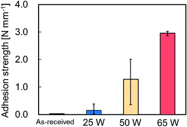
Fig. 1 shows the photographs of thermally-compressed plasma-treated PTFE/IIR sample during the T-peel test. These photographs revealed that the IIR sheet was torn in the middle. ESI-1† is a video about the IIR material failure during the T-peel test. This indicates that the adhesion strength between IIR and plasma-treated PTFE is extremely high despite the absence of adhesives and extremely low adhesion property of original PTFE. Fig. 2 shows the average adhesion strengths between IIR and plasma-treated PTFE samples at different applied RF power. When plasma-treated at 25 W, PTFE presented a slightly stronger adhesion to IIR than its as-received counterpart. Plasma treatment further enhanced the adhesion strength at 50 W and even more drastically at 65 W. The breaking strength of IIR amounted to about 2.0 N mm−1, which caused materials incorporating PTFE plasma-treated at 65 W to fail in the middle of the IIR sheet during the T-peel test (Fig. 1). To explain the sharp increase in adhesion strength, the influence of the applied RF power on PTFE surface was investigated.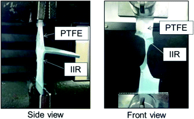 | ||
| Fig. 1 Photographs of IIR being torn in the middle of the T-peel test because of its high adhesion strength. | ||
 | ||
| Fig. 2 Average adhesion strengths between IIR and plasma-treated PTFE samples at different applied RF power. | ||
Fig. 3a shows the ESR spectra of the plasma-treated PTFE samples at different applied RF power. Except for the ESR spectrum of as-received PTFE, all ESR spectra displayed broad peaks indexed to peroxy radical (C–O–O˙) between 332 and 337 mT. All applied RF power conditions gave rise to asymmetric spectra. In general, carbon atoms defluorinated via plasma treatment react with oxygen molecules in the atmosphere, which resulted in formation of peroxy radicals. According to Momose et al., these peroxy radicals consist of mid-chain (–CF2CFOO˙CF2–) and end-chain radicals (–CF2CF2CF2OO˙),26 which can therefore be discriminated from the shape of the ESR spectra. Symmetric spectra are indicative of end-chain peroxy radicals because the peroxy radicals rotate freely. In contrast, an asymmetric spectrum is consistent with mid-chain peroxy radicals because these peroxy radicals exhibit partially restricted rotation. Consequently, plasma-treated PTFE at atmospheric pressure contained more mid-chain than end-chain peroxy radicals in this study. Fig. 3b shows the radical density ratios calculated from the ESR spectra (Fig. 3a). The radical density ratio increased with increasing the applied RF power. Plasma treatment produced a radical density ratio at 65 W twice as high as 25 W. However, plasma treatment at 65 W led to an adhesion strength about 20 times as high as at 25 W, as shown in Fig. 2. This difference indicates that the adhesion strength improved to a greater extent than the radical density ratio. In short, other factors may contribute to this improvement.
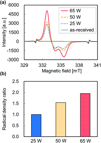 | ||
| Fig. 3 ESR data of the plasma-treated PTFE samples at different applied RF power. (a) ESR spectra and (b) radical density ratio. | ||
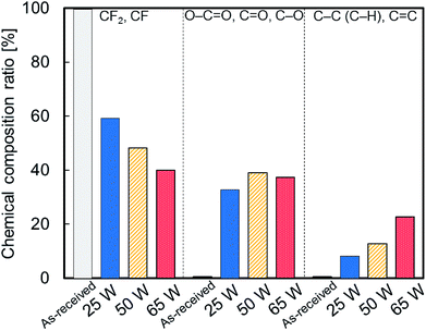
Fig. 4 shows the chemical composition ratios of fluorine (CF2, C–F), oxygen (O–C![[double bond, length as m-dash]](https://www.rsc.org/images/entities/char_e001.gif) O, C
O, C![[double bond, length as m-dash]](https://www.rsc.org/images/entities/char_e001.gif) O, C–O) and carbon (C–C, C–H, C
O, C–O) and carbon (C–C, C–H, C![[double bond, length as m-dash]](https://www.rsc.org/images/entities/char_e001.gif) C) groups for as-received and plasma-treated PTFE samples at different applied RF power. The ratio of fluorine groups decreased upon plasma treatment and decreased further with increasing the applied RF power. This suggests that C–F bonds scissions occur on the PTFE surface via plasma treatment. The ratio of oxygen groups increased upon plasma treatment and surface exposure to atmospheric oxygen. However, it remained intact with increasing the applied RF power. In contrast, the ratio of carbon groups increased upon plasma treatment and increased further with increasing the applied RF power. These results imply that plasma treatment generates C–C crosslinks on the PTFE surface at higher applied RF power.
C) groups for as-received and plasma-treated PTFE samples at different applied RF power. The ratio of fluorine groups decreased upon plasma treatment and decreased further with increasing the applied RF power. This suggests that C–F bonds scissions occur on the PTFE surface via plasma treatment. The ratio of oxygen groups increased upon plasma treatment and surface exposure to atmospheric oxygen. However, it remained intact with increasing the applied RF power. In contrast, the ratio of carbon groups increased upon plasma treatment and increased further with increasing the applied RF power. These results imply that plasma treatment generates C–C crosslinks on the PTFE surface at higher applied RF power.
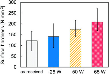
Fig. 5 shows the average surface hardness of the plasma-treated PTFE samples at different applied RF power. This average surface hardness increased steadily with increasing the applied RF power, albeit with a certain degree of variation. This result indicates that plasma treatment hardens the PTFE surface because it etches WBL and/or forms C–C crosslinks.
Fig. 6 shows the average surface temperature of the plasma-treated PTFE samples at different applied RF power. The surface temperature increased with increasing the applied RF power. In particular, the surface temperature reached 250 °C when plasma-treated at 65 W. Heat may increase the PTFE chain mobility as well as carbon and fluorine atoms desorption rate on the outermost PTFE surface. This may enhance the probability of encountering carbon radicals and etching rate of PTFE surface, which may promote crosslinking and/or removal of WBL. To examine the effect of heating on crosslinking, PTFE sheets were just heated in a pot at 300, 350 and 400 °C without plasma treatment. Their surface hardness did not change. These results indicate the importance of simultaneous plasma irradiation and heating. In fact, heat-assisted plasma treatment promotes C–C crosslink formation and/or WBL etching on the PTFE surface. Numerous studies suggest that crosslinking occurs via irradiation with ion beams,27,28 gamma rays,29–31 and electron beams.29,32,33 Also, many reports have addressed etching via plasma treatment, but dealt with crosslinking. This difference may originate from the degree of difficulty in the measurements. The crosslinking of PTFE via radiation irradiation was easily confirmed by nuclear magnetic resonance (NMR) because of its thick modification depth.34 In contrast, no peak was observed for CF and/or branched CF2 in the NMR spectra of plasma-treated PTFE at 65 W because of its thin modification depth (not shown here). These NMR results clearly demonstrate that heat-assisted plasma treatment modifies the surface while keeping the PTFE bulk structure intact. Schonhorn et al. proposed a surface treatment called as crosslinking by activated species of inert gases.35,36 Surface temperature is a critical parameter for the crosslinking reaction during plasma treatment and the result of surface temperature in this study would be useful data for complementing Schonhorn's opinion.
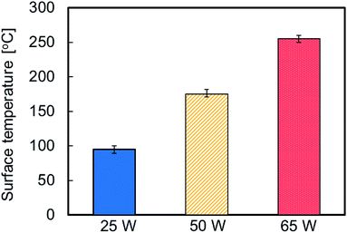 | ||
| Fig. 6 Average surface temperature of the plasma-treated PTFE samples at different applied RF power. | ||
Fig. 7 shows the backscattered electron images (BEIs) of a PTFE surface before and after heat-assisted plasma treatment at 65 W. The as-received PTFE surface exhibited several cutting scratches and pits (Fig. 7a), which decreased on plasma-treated PTFE surface at 65 W (Fig. 7b). This change in surface morphology agrees with surface temperature results. In addition, the decrease in surface roughness after heat-assisted plasma treatment means that the anchor effect does not explain for the drastic increase in adhesion strength.
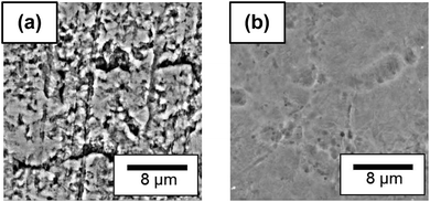 | ||
| Fig. 7 Backscattered electron images (BEIs) of PTFE surface before (a) and after heat-assisted plasma treatment at 65 W (b). | ||
Fig. 8 shows the XPS spectra of the surface of the IIR side after T-peel test on a specimen containing plasma-treated PTFE at 25 W and showing low adhesion strength. These spectra displayed signals for CF2 and F are detected. In general, a very thin film of CF2 chains is readily transferred from the PTFE sheet surface to a contact surface.37 In this study, some CF2 chains present on the PTFE sheet surface were transferred to the surface of the IIR because of crosslinking shortage during plasma treatment at 25 W, which results in poor heat supply.
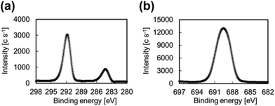 | ||
| Fig. 8 XPS spectra of the surface of IIR side after T-peel test involving a specimen containing IIR and plasma-treated PTFE at 25 W: (a) C1s and (b) F1s. | ||
Two models may be proposed for adhesion and peeling processes (Fig. 9). An as-received PTFE sheet had a WBL containing many cutting scratches and pits (Fig. 7a). A PTFE sheet cannot be obtained by a melt molding method. Therefore, a cylindrical PTFE product is formed by a powder compression molding method and subsequently cut into a sheet. When plasma-treated at 25 W, the PTFE surface changes while retaining its WBL (Fig. 9a). This gives rise to PTFE inter-layer peeling in the WBL. In contrast, this phenomenon does not occur upon plasma treatment at 65 W but the IIR sheet fails instead. This material failure stems from the extremely high adhesion strength, which results from the PTFE surface modification and WBL recovery during heat-assisted plasma treatment (Fig. 9b). Therefore, heat plays a significant role on the adhesion strength between a PTFE sheet and different materials during plasma treatment.
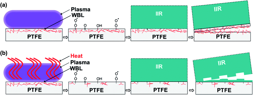 | ||
| Fig. 9 Model showing the adhesion improvement for the plasma-treated PTFE (a) at 25 W; conventional plasma treatment and (b) at 65 W; heat-assisted plasma treatment. | ||
Fig. 10a shows the ESR spectra of the PTFE samples plasma-treated at 65 W acquired after 0, 32, 91, 182 and 340 days. The ESR peak area of PTFE obtained after 0 day was used as reference. Corresponding radical density ratios are shown in Fig. 10b. The radical density ratio decreased to about 90% after 32 days before decreasing slightly with increasing the elapsed time. It reached a value of about 80% after 340 days. In fact, over 80% of radicals formed the preceding year remained in the PTFE samples. The WCA was also measured at different time intervals and amounted to 75.1 ± 0.4, 77.0 ± 0.7 and 80.6 ± 0.4°, after 0, 30 and 337 days, respectively. The PTFE sample plasma-treated at 65 W exhibited lower WCAs (75.1 ± 0.4°) than as-received analogue (115.8 ± 0.9°). This indicates that the plasma-treated surface becomes slightly hydrophilic, in agreement with the decrease in ratio of fluorine groups and the increase in ratios of oxygen and carbon groups (Fig. 4). In addition, the WCA after 337 days (80.6 ± 0.4°) was also sufficiently lower than that for as-received PTFE (115.8 ± 0.9°). Even after almost a year, these values remained nearly the same as the results of the C–C crosslink formation. Typically, WCAs increase with increasing time for plasma-treated polymers because hydrophilic functional groups get under the bulk layer. On the other hand, WCA barely changed for PTFE samples plasma-treated at 65 W. This indicates that C–C crosslinks form on the PTFE surface, preventing hydrophilic functional groups from getting under the bulk layer. Fig. 10c shows the photographs of the IIR/PTFE composite after the T-peel test. Unexpectedly, IIR failed even after almost a year had passed since PTFE samples were subjected to heat-assisted plasma treatment. These ESR, WCA and T-peel test results demonstrate that the lifetime of the surface modification by heat-assisted plasma treatment is extremely longer than expected.
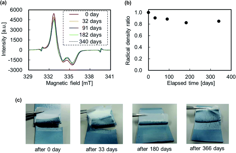 | ||
| Fig. 10 Lifetime of the plasma-treated PTFE samples at 65 W: (a) ESR spectra, (b) radical density ratio and (c) photographs of IIR/PTFE composite after T-peet test. | ||
Conclusions
The adhesion strength between PTFE and IIR was improved by heat-assisted plasma treatment without needing surface graft polymers and adhesive materials. The maximum adhesion strength exceeded 2.0 N mm−1, which resulted in IIR material failure in the middle of the T-peel test. The XPS measurements, nanoindentation hardness tests and WCA results indicated that the C–C crosslink formation and/or WBL etching occurred on the PTFE surface via heat-assisted plasma treatment. This drastically improved the adhesion property of PTFE and prolonged the lifetime of the surface modification. Overall, the recovery of a WBL in PTFE through crosslinking and etching was a key point for boosting the adhesion property of PTFE. In the future, surface modification via heat-assisted plasma treatment may find an application as a useful method for connecting poorly adhesive fluoropolymers to different materials.Acknowledgements
The study was supported by a grant from the Japan Society for the Promotion of Science (JSPS KAKENHI Grant Number 15K05723). ESR and NMR measurements were performed with the help of the staffs of JEOL Ltd. We thank them for their assistance.Notes and references
- D. K. Owens and R. C. Wendt, J. Appl. Polym. Sci., 1969, 13, 1741–1747 CrossRef CAS
.
- L. H. Lee, Langmuir, 1996, 12, 1681–1687 CrossRef CAS
.
- P. Thomas, Surf. Coat. Int., 1998, 81, 604–609 CrossRef CAS
.
- E. L. Bradley, W. A. Read and L. Castle, Food Addit. Contam., 2007, 24, 326–335 CrossRef CAS PubMed
.
- J. Xu, M. H. Zhu and Z. R. Zhou, Thin Solid Films, 2004, 457, 320–325 CrossRef CAS
.
- L. Li, P. M. Jones and Y. T. Hsia, Appl. Surf. Sci., 2011, 257, 4478–4485 CrossRef CAS
.
- J. T. Marchesi, H. D. Keith and A. Garton, J. Adhes., 1992, 39, 185–205 CrossRef CAS
.
- M. Okubo, M. Tahara, Y. Aburatani, T. Kuroki and T. Hibino, IEEE Trans. Ind. Appl., 2010, 46, 1715–1721 CrossRef CAS
.
- M. E. Ryan and J. P. S. Badyal, Macromolecules, 1995, 28, 1377–1382 CrossRef CAS
.
- D. J. Wilson, R. L. Williams and R. C. Pond, Surf. Interface Anal., 2001, 31, 385–396 CrossRef CAS
.
- N. Vandencasteele, H. Fairbrother and F. Reniers, Plasma Processes Polym., 2005, 2, 493–500 CrossRef CAS
.
- N. Vandencasteele, D. Merche and F. Reniers, Surf. Interface Anal., 2006, 38, 526–530 CrossRef CAS
.
- S. L. Kaplan, E. S. Lopata and J. Smith, Surf. Interface Anal., 1993, 20, 331–336 CrossRef CAS
.
- T. Wang, E. T. Kang, K. G. Neoh, K. L. Tan, C. Q. Cui and T. B. Lim, J. Adhes. Sci. Technol., 1997, 11, 679–693 CrossRef CAS
.
- K. M. Baumgärtner, J. Schneider, A. Schulz, J. Feichtinger and M. Walker, Surf. Coat. Technol., 2001, 142–144, 501–506 CrossRef
.
- C. L. Li, C. Y. Tu, J. S. Huang, Y. L. Liu, K. R. Lee and J. Y. Lai, Surf. Coat. Technol., 2006, 201, 63–72 CrossRef CAS
.
- M. Okubo, M. Tahara, N. Saeki and T. Yamamoto, Thin Solid Films, 2008, 516, 6592–6597 CrossRef CAS
.
- D. J. Wilson, A. J. Eccles, T. A. Steele, R. L. Williams and R. C. Pond, Surf. Interface Anal., 2000, 30, 36–39 CrossRef CAS
.
- D. J. Wilson, R. L. Williams and R. C. Pond, Surf. Interface Anal., 2001, 31, 397–408 CrossRef CAS
.
- S. Zanini, R. Barni, R. D. Pergola and C. Riccardi, J. Phys. D: Appl. Phys., 2014, 47, 325202 CrossRef
.
- H. Nakano, Japan Pat., 2013-35988, 2013
.
- Y. Yamamoto, H. Akiyama, K. Ooka, Y. Yamamura, Y. Oshikane and N. Zettsu, Curr. Appl. Phys., 2012, 12, S63–S68 CrossRef
.
- J. Díaz, G. Paolicelli, S. Ferrer and F. Comin, Phys. Rev. B: Condens. Matter Mater. Phys., 1996, 54, 8064–8069 CrossRef
.
- N. Vandencasteele and F. Reniers, J. Electron Spectrosc. Relat. Phenom., 2010, 178–179, 394–408 CrossRef CAS
.
- J. Hubert, T. Dufour, N. Vandencasteele, S. Desbief, R. Lazzaroni and F. Reniers, Langmuir, 2012, 28, 9466–9474 CrossRef CAS PubMed
.
- Y. Momose, Y. Tamura, M. Ogino and S. Okazaki, J. Vac. Sci. Technol., A, 1992, 10, 229–238 CAS
.
- J. Rafiee, X. Mi, H. Gullapalli, A. V. Thomas, F. Yavari, Y. Shi, P. M. Ajayan and N. A. Koratkar, Nat. Mater., 2012, 11, 217–222 CrossRef CAS PubMed
.
- K. Watari, T. Iwao and M. Yumoto, Electr. Eng. Jpn., 2012, 178, 1–7 CrossRef
.
- A. Oshima, Y. Tabata, H. Kudoh and T. Seguchi, Radiat. Phys. Chem., 1995, 45, 269–273 CrossRef CAS
.
- A. Oshima, T. Seguchi and Y. Tabata, Polym. Int., 1999, 48, 996–1003 CrossRef CAS
.
- S. Ikeda, Y. Tabata, H. Suzuki, T. Miyoshi and Y. Katsumura, Radiat. Phys. Chem., 2008, 77, 401–408 CrossRef CAS
.
- E. Katoh, H. Sugisawa, A. Oshima, Y. Tabata, T. Seguchi and T. Yamazaki, Radiat. Phys. Chem., 1999, 54, 165–171 CrossRef CAS
.
- A. Oshima, S. Ikeda, E. Katoh and Y. Tabata, Radiat. Phys. Chem., 2001, 62, 39–45 CrossRef CAS
.
- B. Fuchs, U. Lappan, K. Lunkwitz and U. Scheler, Macromolecules, 2000, 35, 9079–9082 CrossRef
.
- R. H. Hansen and H. Schonhorn, J. Polym. Sci., Part B: Polym. Lett., 1966, 4, 203–209 CrossRef
.
- H. Schonhorn and R. H. Hansen, J. Appl. Polym. Sci., 1967, 11, 1461–1474 CrossRef
.
- K. Tanaka, Y. Uchiyama and S. Toyooka, Wear, 1973, 23, 153–172 CrossRef CAS
.
Footnote |
| † Electronic supplementary information (ESI) available: Video about the IIR material failure during the T-peel test. See DOI: 10.1039/c6ra27642c |
| This journal is © The Royal Society of Chemistry 2017 |

