 Open Access Article
Creative Commons Attribution 3.0 Unported Licence
Promising biomass-derived hierarchical porous carbon material for high performance supercapacitor†
Yuqing Huanga,
Jian Hea,
Yuting Luana,
Yong Jianga,
Shien Guoa,
Xugang Zhangb,
Chungui Tian*a and
Baojiang Jiang *a
*a
aKey Laboratory of Functional Inorganic Material Chemistry, Ministry of Education of the People's Republic of China, Heilongjiang University, Harbin, China. E-mail: chunguitianhq@163.com; jiangbaojiang88@sina.com
bInstitute of Petrochemistry, Heilongjiang Academy of Science, Harbin 150040, China
First published on 7th February 2017
Abstract
Herein, we report a simple method towards a hierarchical porous carbon material using biomass rice husk ash as the carbon resource. The carbon material possesses a hierarchical pore structure after a pre-treatment and calcination procedure. The specific surface area of the resulting rice husk porous carbon (RHPC) shows an evident increase in its capacitance due to the effective area of contact between the electrolyte solution and electrode material. The RHPC delivers a great specific capacitance of 260 F g−1 at 1 A g−1 and exhibits outstanding rate capability with an excellent charging/discharging cycle stability (14% loss after 10![[thin space (1/6-em)]](https://www.rsc.org/images/entities/char_2009.gif) 000 cycles) at a current density of 20 A g−1. The RHPC shows an excellent electrochemical performance attributed to the large surface area and good electrical conductivity. The porous carbon from biomass rice husk ash shows the potential of the application in energy storage.
000 cycles) at a current density of 20 A g−1. The RHPC shows an excellent electrochemical performance attributed to the large surface area and good electrical conductivity. The porous carbon from biomass rice husk ash shows the potential of the application in energy storage.
1. Introduction
The world's demand for sustainable energy is ever-increasing due to social development. Energy storage technology for harvesting sustainable energy sources is one of the most significant research fields. Supercapacitors (SCs) have received more and more attention as next-generation energy storage devices because of their charge/discharge stability, long life-cycle performance and high power density. SCs are usually divided into three categories.1 One is electric double-layer capacitors (EDLCs), which normally provide energy by carbon electrodes or a derivate.2–4 Another is pseudocapacitors that power-store through reversible redox processes at the surface of the electroactive material.5 The last is hybrid capacitors such as the EDLCs and the pseudocapacitors.6,7Among them, the EDLCs are the most commonly applied in energy storage mode.8 Among various electrode materials for EDLCs, carbon materials are the most widely investigated electrode active materials.9 Carbon-based EDLCs have reliable electrochemical performances and long-term cycling stability due to their electronic conductivity, high specific surface area (SSA) and appropriate pore size.10,11 More abundant, renewable and sustainable carbon materials are urgently needed to meet the demand of wide-ranging energy applications.12–14 Biomass is a possible renewable resource of carbon materials for use as SC electrode materials and currently about ∼14% of the world's energy is produced by biomass due to the fact that it is easily available, low cost, renewable and more friendly to the environment compared with the fossil fuels.15–20 Activated carbons (ACs) are widely used as EDLC electrode materials because of their high surface area and plenty of pores of the structure.21,22 Recently, the preparation of activated carbon from biomass materials has received increasing interest. Natural, organic and agricultural wastes, such as corn husks,23 dead leaves,24 wood,25 loofah sponges,26 pistachio nutshells,27 sunflower seed shells,28 rice husks,29 and a mixture of coal-tar pitch and sawdust,30 have been explored as biomass sources using different synthesis procedures, including hydrothermal, carbonization, chemical vapor deposition (CVD), and pyrolysis. Particularly, the 3D interconnected network with open pores in biomass materials provides easy access for guest ions/molecules into the interior, providing them with a more beneficial specific surface area and potential usage as supercapacitor electrode materials.
Rice husk ash is one of the common renewable biomass resources, which is cheap, plentiful and easily available. Rice husk ash is a waste material produced by power plants, which receive power from burning rice husks. Rice husks have been widely used in former works for multiple purposes,31–34 but rice husk ash is rarely used in the preparation of carbon materials. Herein, we report a simple method to prepare hierarchical porous carbon materials using industrial waste rice husk ash (RHA). During the preparation process, most of the silica dioxide was removed. Moreover, the porous structure is well maintained in the next step of calcination. We have formed pores in different sizes, and activated materials partially at the same time at room temperature, and thus the synthesis process was simplified. The resulting RHPC has a good electronic conductivity and is produced by a simple procedure, which can deliver a high performing low-cost electrode material for supercapacitors. This study provides the possibility for secondary use of rice husk ash, which is a good manifestation of sustainable energy.
2. Experimental
2.1 Preparation of the porous carbon from rice husk ash
The waste rice husk ash was obtained from a thermal power plant. In the typical preparation process, the rice husk ash (RHA) was firstly sieved by a stainless steel mesh to remove large impurities. Then, 1 g rice husk ash (RHA) and 7.5 mL of hydrofluoric acid (HF, 40 wt%) was mixed into 100 mL deionized water. The mixture was stirred at room temperature for 24 h, washed 5 times with deionized water and ethanol, followed by drying at 80 °C in an oven. Subsequently the dried products were carbonized at 600, 700, 800, 900 and 1000 °C for 2 h under nitrogen with a heating rate of 5 °C min−1 in a tube furnace, and the final samples were denoted as RHPC-T, where T represents the treatment temperature.2.2 Characterization
X-ray powder diffraction (XRD) was obtained by a Bruker D8 diffractometer with nickel-filtered Cu Kα radiation. Raman spectra were conducted with a Jobin Yvon HR 800 micro-Raman spectrometer at 457.9 nm. SEM was performed using a Hitachi S-4800 instrument operating at 5 kV. The transmission electron microscopy (TEM) experiment was performed on a JEM-2100 electron microscope (JEOL, Japan) with an acceleration voltage of 200 kV. X-ray photoelectron spectroscopy (XPS) analysis was performed on a VG ESCALAB MK II with an Mg Kα (1253.6 eV) achromatic X-ray source. Nitrogen adsorption–desorption isotherm measurements were carried out at 77 K using a Micromeritics Tris-tar II. The specific surface area was determined according to the Brunauer–Emmett–Teller (BET) method using a Tristar II 3020 surface area and porosity analyser (micromeritics).2.3 Electrochemical measurements
The electrochemical capacitive performance of RHPC was evaluated and assessed in a three-electrode system. The three-electrode system in 6 mol L−1 KOH aqueous solution consisted of a saturated calomel electrode (SCE) as the reference electrode, a Pt slice as the counter electrode, and RHPC as the working electrode. The working electrode was homogeneously mixed in the agate mortar, which contained 90 wt% of the active material RHPC, 5 wt% poly (tetrafluoroethylene, PTFE) and 5 wt% acetylene black on a nickel foam. The slurry (approximately 4 mg) was then covered onto the nickel foam (1 × 1 cm2) and then placed under vacuum at 60 °C for 6 h. In order to characterize the electrochemical properties of the samples, cyclic voltammetry (CV), galvanostatic charge–discharge (GCD) and electrochemical impedance spectroscopy (EIS) techniques were performed with a computer-controlled IM6e Impedance Analyzer in a frequency range from 0.01 Hz to 100 kHz at an open circuit potential with 5 mV amplitude. The cyclic voltammetry (CV) test was performed on a BAS100B electrochemical work station. The constant current charge–discharge capacitance test was carried out on a CHI 660D (Shanghai CH Instruments Co., China). The specific capacitance was calculated from galvanostatic discharge using the following equation:| C = (IΔt)/(mΔV) |
3. Results and discussion
3.1 Morphology and structure
The structures of RHPC were examined using XRD and Raman spectroscopy. The X-ray diffraction (XRD) profiles in Fig. 1a show that RHPC-600 after hydrofluoric acid and carbonization treatment shows only one broad peak at 24.5°, which is the typical reflection of the (002) plane and is in accordance with the exit of graphite carbon structure. Nevertheless, with the thermal-treatment temperature increased to 800 °C, the XRD patterns show one broad peak at 24.5° and two sharp peaks at 29.2° and 47°, which are the characteristic diffraction peaks of silicon, and the peak located at 26.7° corresponds to silicon dioxide. There is a certain amount of amorphous silicon in the product when the carbonized temperature is below 700 °C, and amorphous silicon turns into silicon dioxide with the rise of temperature. As silicon is a natural template, the material will form a porous structure during the silicon removal process, and in addition, the presence of silicon in carbon materials may have a beneficial effect on the electrochemical properties. In order to further study the structure of the RHPC samples, Raman spectroscopy was analysed in the range from 750 cm−1 to 3500 cm−1. Three featured peaks are located for RHPC (Fig. 1b), which are the D-band (1348 cm−1), G-band (1593 cm−1), and 2D-band (2887 cm−1). The D-band is related to the partially disordered structures and the structural defects that exist in carbon materials. The G-band corresponds to the E2g vibrational mode of 2D graphite, which reflects the crystallinity of the material.35 The 2D-band is the characteristic band of graphitic carbon materials. The relative intensity of the D-band and G-band (ID/IG) reflects the crystallinity of these materials and is proportional to the type of graphitic materials.36 The ratios of RHPC-600 to RHPC-1000 were determined to be 0.76, 0.77, 0.79, 0.82 and 0.86,37,38 indicating good conductivity because of the high crystallinity, which could also be conducive to the rapid transmission of electrons during electrochemical processes.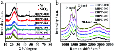 | ||
| Fig. 1 (a) XRD profiles of RHA and RHPC-600 to RHPC-1000, (b) Raman spectra of RHPC-600 to RHPC-1000. | ||
The structure and morphology of RHPC were analysed by scanning electron microscopy (SEM) and transmission electron microscopy (TEM). Fig. 2 shows that the samples of RHPC consist of a hierarchical 3D porous structure with pore sizes distributed in a wide range from around 30–80 nm to 1–2 μm. The hierarchical porous structure enables the electrolyte ions to diffuse faster by increasing the effective contact between electrolyte and carbon materials and reduces the resistance to the interior for electrolyte ions. It is clear from the analysis results that HF treatment and thermal-treatment leads to the formation of a porous structure in the material, contributing to a much higher specific surface area (SSA) than that of RHA. The TEM images (Fig. 2c and d) further certify that RHPC-700 with a porous structure has been produced successfully, particularly from the marked light areas shown in Fig. 2d and S1.† The interlayer spacing is 0.34 nm and it is in accordance with the exit of graphite carbon. As can be seen, the part of graphitized carbon exists at the edge of the sample. Analysis of the crystal structure also corresponds to the powder X-ray diffraction (XRD) and the Raman spectra results. It is well known that a high specific surface area provides more reaction sites for efficient electrochemical interactions/reactions, which is conducive to improve the performance of a supercapacitor. The pore texture of the RHA and RHPC-X materials was analyzed by N2 adsorption/desorption measurements, and the results are shown in Fig. 3 and Table 1. The SSA of RHA was found to be only 0.1476 m2 g−1, and the SSA of RHPC was very significantly increased compared to that of RHA. With the increase of carbonization temperature from 600 °C to 1000 °C, the SSA and pore volume of RHPC changes differently. The specific surface area and pore volume of RHPC-700 are 786.15 m2 g−1 and 0.439 cm3 g−1, respectively. In this study, using rice husk ash as a raw material, the produced RHPC samples exhibit a proper pore size distribution, which could be beneficial for charge storage.39
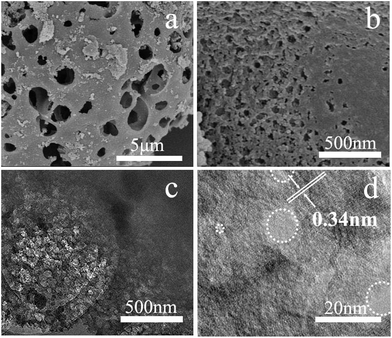 | ||
| Fig. 2 (a and b) SEM images of rice husk porous carbon (RHPC-700), (c and d) TEM images of RHPC-700 under different magnifications. | ||
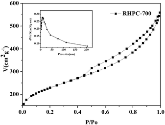 | ||
| Fig. 3 N2 physisorption isotherms and porosity characteristics of RHPC-700, and the inset shows the pore size distribution of RHPC-700. | ||
| BET SSA (m2 g−1) | Total pore volume (cm3 g−1) | Average pore size (nm) | Specific capacitance (F g−1) | |
|---|---|---|---|---|
| RHA | 0.1476 | 0.002 | 121.10 | — |
| RHPC-600 | 597.60 | 0.347 | 7.31 | 192.9 |
| RHPC-700 | 786.15 | 0.439 | 7.03 | 260 |
| RHPC-800 | 667.56 | 0.419 | 7.92 | 231.3 |
| RHPC-900 | 600.62 | 0.349 | 7.18 | 162.4 |
| RHPC-1000 | 577.57 | 0.331 | 7.52 | 105.3 |
In order to analyze the chemical performance and superficial elemental composition of RHPC, series samples were characterized by X-ray photoelectron spectroscopy (XPS). The XPS spectra of RHA and RHPC-700 are shown in Fig. S2† and 4. There are two peaks at 284.7 eV and 532.1 eV, corresponding to C 1s, O 1s and a weak peak at 103.7 eV relating to Si 2p, respectively (Fig. 4a). As shown in Fig. 4b, two peaks at 102.8 eV and 105 eV can be seen corresponding to Si–O and Si–Si in RHPC-700. As can be seen in Fig. 4c, the C 1s spectrum of RHPC-700 is deconvoluted into five sub-peaks, including one main peak at 284.6 eV for sp2-hybridized graphite-like carbon and three other peaks at 285.6, 286.8, and 289.3 eV attributed to sp3-hybridized carbon, C–O, and C![[double bond, length as m-dash]](https://www.rsc.org/images/entities/char_e001.gif) O, respectively.40 As displayed in Fig. 4d, the O 1s spectrum of RHPC-700 was deconvoluted into four established groups including C
O, respectively.40 As displayed in Fig. 4d, the O 1s spectrum of RHPC-700 was deconvoluted into four established groups including C![[double bond, length as m-dash]](https://www.rsc.org/images/entities/char_e001.gif) O (531.0 eV), C–O (531.9 eV), C–OH (533.0 eV), and adsorbed H2O (533.9 eV).41,42 Moreover, there is still a very small amount of silicon species (2.4 wt%) in RHPC, the surface element contents of RHA and RHPC-700 are shown in Table S1.† The thermogravimetry curves of RHPC are also shown in Fig. S3.†
O (531.0 eV), C–O (531.9 eV), C–OH (533.0 eV), and adsorbed H2O (533.9 eV).41,42 Moreover, there is still a very small amount of silicon species (2.4 wt%) in RHPC, the surface element contents of RHA and RHPC-700 are shown in Table S1.† The thermogravimetry curves of RHPC are also shown in Fig. S3.†
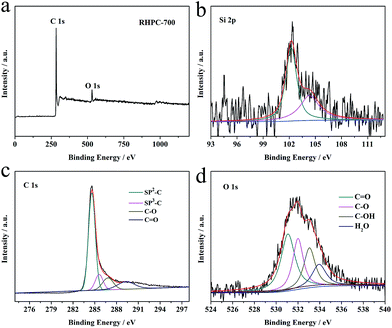 | ||
| Fig. 4 XPS survey spectra of (a) RHPC-700, and Si 1p (b), C 1s (c) and O 1s (d) spectra of RHPC-700. | ||
3.2 Electrochemical performance
The electrochemical performance of RHPC was first characterized by galvanostatic charge–discharge curves in 6 M KOH aqueous solution. Fig. 5 shows the galvanostatic charge–discharge curves of RHPC electrodes at the current density of 1 A g−1. The specific capacitances of RHPC-600, RHPC-700, RHPC-800, RHPC-900 and RHPC-1000 are 192.9 F g−1, 260 F g−1, 213.3 F g−1, 162.4 F g−1, and 105.3 F g−1, respectively. The electrochemical properties of the product are not proportional to the increase of annealing temperature because the pores caused by etching silicon dioxide collapse when the annealing temperature continues to rise. The results indicate that RHPC-700 has the best electrochemical performance among these five samples.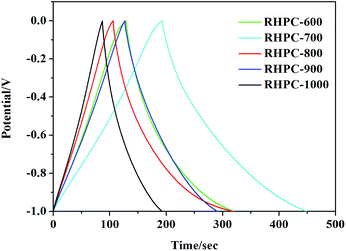 | ||
| Fig. 5 Galvanostatic charge–discharge curves of RHPC-700 to RHPC-1000 with the current density of 1 A g−1. | ||
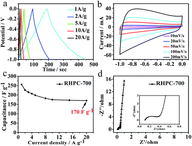
Intending to further investigate RHPC's electrochemical properties, the galvanostatic charge–discharge measurements of RHPC were conducted at different current densities ranging from 1 to 20 A g−1. The specific capacitance can reach 260 F g−1 at the current density of 1 A g−1 with a capacitance of 170 F g−1 at a higher current density of 20 A g−1 (Fig. 6a and c), which suggests that RHPC has an excellent rate performance. The specific capacitance of RHPC-700 is 294.5 F g−1 at the current density of 0.5 A g−1 (Fig. S4†). Considering that, the rate performance is in good agreement with the CVs for power applications. To evaluate the capacitive performance of the RHPC-700 electrode, CV tests at different scan rates were also performed. As shown in Fig. 6b, with the scan rate increasing from 10 to 200 mV s−1, the CV curves of RHPC-700 exhibit a shape where no remarkable peaks can be observed, indicating the typical charge/discharge process of an electrical double layer capacitor. CV curves also show a good electrochemical capacitive behavior with easy transportation of electrolyte ions caused by the hierarchical pore structure. Fig. 6d displays the electrochemical impedance spectroscopy (EIS) observations of RHPC-700 in a 6 M KOH solution at a frequency range of 0.01 Hz to 100 kHz with an alternate current amplitude of 5 mV. As seen in Fig. 6d, the line that results is almost 90° indicating good capacitor behavior of RHPC-700 in the low-frequency region, and the high frequency semicircle region observed a typical carbon-based supercapacitor behavior, which is related to the electrical resistance of the electrode material that determines the power capability of a capacitor.43
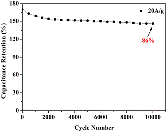
A remarkably stable performance of RHPC-700 was observed. As shown in Fig. 7, after 10![[thin space (1/6-em)]](https://www.rsc.org/images/entities/char_2009.gif) 000 charge/discharge cycles at a high current density of 20 A g−1, the capacitance retention of RHPC-700 is still beyond 86%, suggesting that the exiting of a small amount of SiO2 maintained hierarchical porous carbon structures, which allows access to electrolyte ions leading to long-term cycling lives and outstanding reversibility of the RHPC electrode.
000 charge/discharge cycles at a high current density of 20 A g−1, the capacitance retention of RHPC-700 is still beyond 86%, suggesting that the exiting of a small amount of SiO2 maintained hierarchical porous carbon structures, which allows access to electrolyte ions leading to long-term cycling lives and outstanding reversibility of the RHPC electrode.
4. Conclusion
In summary, we synthesized hierarchical porous carbon materials by employing a quantity of waste rice husk ash as a carbon precursor. In this study, RHPC-700 exhibited a high specific surface area of 786.15 m2 g−1, and the electrochemical measurements show that RHPC-700 offers an outstanding specific capacitance of 260 F g−1 and excellent cycling stability. We developed a simple, low-cost approach for creating a new direction to synthesize capacitor electrode materials from an abundant biomass resource to realize promising energy storage technology.Acknowledgements
This study was supported by the National Natural Science Foundation of China (51372071, 21571054).Notes and references
- J. R. Miller and P. Simon, Science, 2008, 321, 651 CrossRef CAS PubMed.
- L. Zhao, L. Z. Fan, M. Q. Zhou, H. Guan, S. Qiao, M. Antonietti and M. M. Titirici, Adv. Mater., 2010, 22, 5202 CrossRef CAS PubMed.
- R. Dong, Q. Ye, L. Kuang, X. Lu, Y. Zhang, X. Zhang, G. Tan, Y. Wen and F. Wang, ACS Appl. Mater. Interfaces, 2013, 5, 9508 CAS.
- P. Tang, L. Han and L. Zhang, ACS Appl. Mater. Interfaces, 2014, 6, 10506 CAS.
- P. Simon and Y. Gogotsl, Nat. Mater., 2008, 7, 845–854 CrossRef CAS PubMed.
- L. L. Zhang and X. S. Zhao, Chem. Soc. Rev., 2009, 38, 2520 RSC.
- S. Park, I. Nam, G. P. Kim, J. W. Han and J. Yi, ACS Appl. Mater. Interfaces, 2013, 5, 9908 CAS.
- K. Yan, L. Kong, K. Shen, Y. Dai, M. Shi, B. Hu, Y. Luo and L. Kang, Appl. Surf. Sci., 2016, 364, 850–861 CrossRef CAS.
- M. Zhi, F. Yang, F. Meng, M. Li, A. Manivannan and N. Wu, ACS Sustainable Chem. Eng., 2014, 2, 1592–1598 CrossRef CAS.
- A. Bello, N. Manyala, F. Barzegar, A. A. Khaleed, D. Y. Momodu and J. K. Dangbegnon, RSC Adv., 2016, 6, 1800–1809 RSC.
- M. Zhou, T. Tian, X. F. Li, X. D. Sun, J. Zhang, Y. H. Chen, P. Cui, J. Tang and L.-C. Qin, Chem. Phys. Lett., 2013, 581, 64–69 CrossRef CAS.
- Y. Zhai, Y. Dou, D. Zhao, P. F. Fulvio, R. T. Mayes and S. Dai, Carbon Materials for Chemical Capacitive Energy Storage, Adv. Mater., 2011, 23, 4828–4850 CrossRef CAS PubMed.
- X. Li and B. Wei, Nano Energy, 2013, 2, 159–173 CrossRef CAS.
- J. Wang and S. Kaskel, J. Mater. Chem., 2012, 22, 23710–23725 RSC.
- R. C. Saxena, D. K. Adhikari and H. B. Goyal, Renewable Sustainable Energy Rev., 2009, 13, 167–178 CrossRef.
- A. Faaij, Atmospheric Sciences, 2006, 11, 335–367 Search PubMed.
- K. Sanderson, Nature, 2006, 444, 673–676 CrossRef CAS PubMed.
- S. E. Koonin, Science, 2006, 311, 435 CrossRef CAS PubMed.
- R. S. Dhillon and G. von Wuehlisch, Biomass Bioenergy, 2013, 48, 75–89 CrossRef.
- Y. Luan, Y. Huang, L. Wang, M. Li, R. Wang and B. Jiang, J. Electroanal. Chem., 2016, 763, 90–96 CrossRef CAS.
- Y. Zhang, X. Li, J. Huang, W. Xing and Z. Yan, Nanoscale Res. Lett., 2016, 11, 163 CrossRef PubMed.
- X. Zhou, L. Li, S. Dong, X. Chen, P. Han, H. Xu, J. Yao, C. Shang, Z. Liu and G. Cui, J. Solid State Electrochem., 2012, 16, 877–882 CrossRef CAS.
- I. I. G. Inal, S. M. Holmes, A. Banford and Z. Aktas, Appl. Surf. Sci., 2015, 357, 696–703 CrossRef CAS.
- S. Song, F. Ma, G. Wu, D. Ma, W. Geng and J. Wan, J. Mater. Chem. A, 2015, 3, 18154 CAS.
- H. Wang, Z. Xu, A. Kohandehghan, Z. Li, K. Cui, X. Tan, T. J. Stephenson, C. K. King'ondu, C. M. B. Holt, B. C. Olsen, T. Jin Kwon, D. Harfield, A. Anthony, O. Anyia and M. David, ACS Nano, 2013, 7, 5131–5141 CrossRef CAS PubMed.
- L. Wei, M. Sevilla, A. B. Fuertes, R. Mokaya and G. Yushin, Adv. Energy Mater., 2011, 1, 356–361 CrossRef CAS.
- Y. T. Luan, L. Wang, S. E. Guo, B. J. Jiang, D. D. Zhao, H. J. Yan, C. G. Tian and H. G. Fu, RSC Adv., 2015, 5, 42430 RSC.
- J. Xu, Q. Gao, Y. Zhang, Y. Tan, W. Tian, L. Zhu and L. Jiang, Sci. Rep., 2014, 4, 5545 CAS.
- X. Li, W. Xing, S. Zhuo, J. Zhou, F. Li, S.-Z. Qiao and G.-Q. Lu, Bioresour. Technol., 2011, 102, 1118–1123 CrossRef CAS PubMed.
- S. Kumagai, M. Sato and D. Tashima, Electrochim. Acta, 2013, 114, 617–626 CrossRef CAS.
- Y. Li, F. Wang, J. Liang, X. Hu and K. Yu, New J. Chem., 2016, 40, 325 RSC.
- D. Liu, W. Zhang, H. Lin, Y. Li, H. Lu and Y. Wang, RSC Adv., 2015, 5, 19294 RSC.
- G. Wang, D. Wang, S. Kuang, W. Xing and S. Zhuo, Renewable Energy, 2014, 63, 708 CrossRef CAS.
- L. P. Wang, Z. Schnepp and M. M. Titirici, J. Mater. Chem. A, 2013, 1, 5269 CAS.
- X. Wang, T. Wang, C. Yang, H. Li and P. Liu, Appl. Surf. Sci., 2013, 287, 242–251 CrossRef CAS.
- G. Zhu, H. Y. Wang and L. Zhang, Chem. Phys. Lett., 2016, 649, 15–18 CrossRef CAS.
- X. Ma, L. Gan, M. Liu, P. K. Tripathi, Y. Zhao, Z. Xu, D. Zhu and L. Chen, J. Mater. Chem. A, 2014, 2, 8407 CAS.
- F. Ma, H. Zhao, L. Sun, Q. Li, L. Huo, T. Xia, S. Gao, G. Pang, Z. Shi and S. Feng, J. Mater. Chem., 2012, 22, 13464 RSC.
- F. Sun, J. Gao, X. Liu, X. Pi, Y. Yang and S. Wu, Appl. Surf. Sci., 2016, 387, 857–863 CrossRef CAS.
- L. Zhang, Z. Su, F. Jiang, L. Yang, J. Qian, Y. Zhou, W. Li and M. Hong, Nanoscale, 2014, 6, 6590 RSC.
- E. C. Vermisoglou, T. Giannakopoulou, G. E. Romanos, N. Boukos, M. Giannouri, C. Lei, C. Lekakou and C. Trapalis, Appl. Surf. Sci., 2015, 358, 110–121 CrossRef CAS.
- R. Madhu, V. Veeramani, S.-M. Chen, A. Manikandan, A.-Y. Lo and Y.-L. Chueh, ACS Appl. Mater. Interfaces, 2015, 7, 15812–15820 CAS.
- F. F. Zhang, J. Tang, N. Shinya and L.-C. Qin, Chem. Phys. Lett., 2013, 548, 124–129 CrossRef.
Footnote |
| † Electronic supplementary information (ESI) available. See DOI: 10.1039/c6ra27788h |
| This journal is © The Royal Society of Chemistry 2017 |

