 Open Access Article
Creative Commons Attribution 3.0 Unported Licence
Stability and clusterization of hydrogen-vacancy complexes in B2-FeAl: insight from hydrogen embrittlement
Guikai Zhangabc,
Guangqi Huangb,
Meijuan Hua,
Feilong Yanga,
Lang Liua,
Jürgen Konys*c and
Tao Tang *ab
*ab
aChina Academy of Engineering Physics, Institute of Materials, Jiangyou, 621908, China. E-mail: Tangtao@caep.cn
bScience and Technology on Surface Physics and Chemistry Laboratory, Mianyang 621907, China
cKarlsruhe Institute of Technology, Institute for Applied Materials, Hermann-von-Helmholtz-Platz 1, 76344 Eggenstein-Leopoldshafen, Germany. E-mail: Juergen.konys@kit.edu
First published on 13th February 2017
Abstract
Little is known about hydrogen-vacancy interactions and their contributions to hydrogen embrittlement (HE) in iron aluminides. H-induced vacancy formation, stability and clusterization of hydrogen-vacancy complexes (VFeHn) in B2-FeAl were studied via density functional theory (DFT) and thermodynamic formalism. The presence of an interstitial H atom in FeAl forms superabundant Fe-vacancies. The H atoms are more likely to be trapped around the Fe-vacancies than diffuse from one octahedral interstitial site to another. One Fe-vacancy can trap at most six H atoms to form VFeHn complexes with H atoms occupying the six first-nearest-neighbor (1NN) Oct2Fe–4Al sites of VFe one by one; the H–H distances are 1.920–2.785 Å. The VFeH6 complex is the major complex under ambient conditions and prefers to grow larger by clusterization of V2FeH12 units along 〈100〉 and {100} with internal H2 molecules closely associated with the crack along the {100} planes. Thus we propose a mechanism of isotropic hydrogenated vacancy-cluster induced HE: hydrogen addition-induced isotropic V2FeH12〈100〉 clusters of line and planar shapes are embryos for the formation of cracks and H2 bubbles. This grows ever bigger as a function of H concentration and eventually leads to the macroscopic failure observed experimentally.
1. Introduction
Iron aluminides have been widely studied as high-temperature structural materials because of their high mechanical strength, excellent corrosion/oxidation resistance and low cost. However, they tend to fail when exposed to a small amount of hydrogen or water due to their susceptibility to hydrogen embrittlement (HE).1–10 Thus, the nature, causes, and control of HE of iron aluminides are of particular interest, which is a major concern in many industries including oil and gas, off-shore wind turbines, and hydrogen gas transport.The HE of iron aluminides has been investigated since the 1980s.1–7 The crack in FeAl propagates mainly along the {100} plane in air. In contrast, in a vacuum, fracture occurs along {111} for stoichiometric Fe–Al, {100} for Fe–40Al, and Fe–35Al.2,3 The ductility of Fe–40Al single-slip-oriented single crystals is lower in air than in a vacuum.5 Screw oriented single crystals of Fe3Al have considerable ductility in both air and a vacuum, whereas the edge-oriented specimens have little ductility in air.6 A sessile 〈100〉 edge dislocation on {001} may be produced by the interaction of two a/2 〈111〉 edge super-partials.7 However, experiments to date are limited to the effect of hydrogen on ductility, crack initiation on {100}, and fractures along {111} and {100} planes, etc. These have been further discussed with hydrogen-enhanced decohesion (HEDE), adsorption-induced dislocation emission (AIDE) and hydrogen-enhanced local plasticity (HELP) theories.8–10 These studies detail new surface formation, bond weakening, hydrogen-dislocation interaction as well as their consequences on HE. However, the atomic level mechanism underlying the formation of 〈100〉 edge dislocations, cracks, and fractures is still unclear, including how these failures occur in a defined environment. It is critical to identify fundamentals and create a suppression strategy while also explaining the mechanism of HE in iron aluminides.
VFe can enhance hydrogen solubility in iron aluminides. They have a high concentration of vacancies (two-fold higher than that of pure metals and disordered alloys). This increases the influence of hydrogen on the mechanical properties.1 Hydrogen-related degradations might depend on hydrogen and vacancy related-defective properties and their evolvements. This could identify the specific vacancy, hydrogen, or complexes that link the edge dislocation, crack and fracture as result of HE. However, no further relevant thermodynamic and kinetic information regarding hydrogen and vacancy related-defects in iron aluminides and their contribution to HE is reported.
Here, we studied H-induced vacancy formation, vacancy trapping of multiple H, and clusterization of hydrogen-vacancy complexes in B2-FeAl via density functional theory (DFT) and thermodynamics formalism to illustrate the contributions of vacancy-related processes to HE in iron aluminides and to explain experimental results. We also detail the decisive role of VFeHn clusters as embryos for the formation of edge dislocations, cracks, and H2 bubbles. This work attempts to bridge the link between the atomic-scale events of hydrogen-vacancy complexes and the experimentally (microscopically) observed HE of iron aluminides.
2. Computational method and model
DMol3 in Materials Studio of Accelrys Inc. successfully captures the properties of FeAl.11–16 In comparison with local density approximation (LDA) and Perdew, Burke, and Ernzerhof (PBE), the density functions confirm the principal findings for FeAl based on Perdew and Wang (PW91).13,15 Thus, we performed the calculations within the PW91-GGA (generalized gradient approximation) using a double numerical quality basis set with polarization functions (DNP)17 and a semi-core pseudopotential.18 The pseudopotential and the basis set also have been used to study the properties of hydrogen,10,14,19 Fe and Al.20 All spin polarized calculations utilized a convergence tolerance of energy of 2.7 × 10⁻⁶ eV, a maximum force of 5.4 × 10⁻³ eV Å−1, a maximum displacement of 5.0 × 10⁻⁴ Å, a fixed Monkhorst–Pack mesh k-points of 2 × 2 × 2, a real-space cutoff of 5.3 Å and a thermal smearing of 0.002 au. No symmetry constraints were imposed. The lattice and all atoms of the supercell are relaxed fully during the calculations of vacancies and anti-sites. The lattice parameter is fixed with atomic position relaxation during the calculation of H-related defects.With these parameters, energies of the model have converged. For example, in H adsorption, we tested different real-space cutoffs (4.8, 5.3 and 5.8 Å). The adsorption energy only increases by 0.020 eV as the cutoff varies from 4.8 to 5.3 Å. It is 0.028 eV at further increases of the cutoff. Thus, a real-space cutoff of 5.3 Å is sufficient to achieve numerical convergence. It is found that ZPE corrections do not essentially affect the subjects investigated in our work, as shown in ref. 21, thus the results presented here do not include the ZPE corrections.
We obtain a lattice constant of a = 2.888 Å for B2 type FeAl. This agrees reasonably well with previous DFT-GGA calculations (a = 2.875–2.910 Å (ref. 11–14, 22 and 23)) as well as experiment data (a = 2.916 Å (ref. 24)). The calculated binding energy of H2 is 4.565 eV, which is in good agreement with the experimental and other DFT values.23 A vibrational frequency of 4385.60 cm−1 is calculated for H2—in close agreement with experiment (4401.00 cm−1).25
A 4 × 4 × 4 supercell containing 128 atoms was constructed for calculations. This was based on the optimized structural parameters for a perfect B2-type FeAl. To introduce an isolated Al (Fe) vacancy, an Al (Fe) atom at the center of the supercell is removed to produce a 0.76% defect in bulk FeAl. In the case of an antisite, a Fe (Al) atom is put into the Al (Fe) vacancy to produce a 0.76% defect in the bulk. The formation energies of vacancy and antisite in B2-FeAl are shown in Table 1, and compared to previous formation energies. The VFe is more favorable than VAl, and AlFe has lower site preference energy in agreement with previously predicted results.26–29 Therefore, we used VFe for all subsequent calculations.
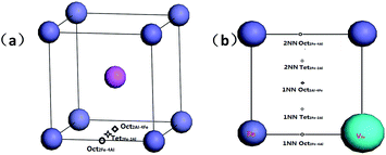
There are three interstitial sites in B2-FeAl including two octahedral interstitial sites and one tetrahedral interstitial site. Fig. 1a shows that the tetrahedral interstitial site consists of two Fe atoms and two Al atoms with bond lengths of (Tet2Fe–2Al). One octahedral interstitial site involves two axial Fe atoms and four equatorial Al (Oct2Fe–4Al). Another one involves two axial Al atoms with four equatorial Fe (Oct2Al–4Fe). In an elementary B2-cell, 12 Tet2Fe–2Al, 3 Oct2Fe–4Al and 3 Oct2Al–4Fe sites can be found. In a pre-existing Fe vacancy in bulk FeAl, two possible interstitial positions are considered (Fig. 1b): (1) H in the first-nearest-neighbor (1NN) octahedral and tetrahedral interstitial sites of the Fe vacancy including 1NN Oct2Fe–4Al, 1NN Oct2Al–4Fe and 1NN Tet2Fe–2Al sites, and (2) the second-nearest-neighbor (2NN) sites including 2NN Oct2Fe–4Al and 2NN Tet2Fe–2Al sites.
The formation energy of interstitial H (VHn complex) in FeAl host is defined as
 | (1) |
The formation energy of a Fe vacancy surrounding one H interstitial atom is defined as
| Ef(V) = E(HOIS,V) − E(HOIS) + E(Fe), | (2) |
The hydrogen-trapping binding energy of VHn complexs are defined as the energy gain by trapping an interstitial hydrogen atom into a vacancy site to form VHn complexes. It has been defined as30
| Etrap(nH) = [E(n − 1H,V) + E(V)] − [E(nH,V) + E(HOIS,V)], | (3) |
Migration barriers for point defects are calculated by complete linear synchronous transit/quadratic synchronous transit (LST/QST) method using eleven images. The frequencies are calculated at all critical points identified on the potential energy surface to identify minima and transition states.
3. Results and discussion
3.1. Interstitial H-induced VFe formation
We first investigated the positions for an individual H atom interstitial in perfect FeAl bulk to discuss the effect of interstitial H atom on vacancy formation.We first investigated the positions for an interstitial H atom in perfect FeAl bulk. As shown in Fig. 1, the interstitial H at the Oct2Al–4Fe site is unstable, whereas the Oct2Fe–4Al site for an interstitial H is energetically more stable than the Tet2Fe–2Al site by 0.02–0.03 eV. This coincides with previous calculations 0.02 eV.23 The corresponding formation energy is 0.50 eV for the H at the Oct2Fe–4Al site with a H–Fe bond length of 1.56 Å. The H–Al bond lengths vary from 2.02 to 2.15 Å (Fig. 2). We find two real modes for the Oct2Fe–4Al hydrogen at 1506.80 cm−1 and 1507.59 cm−1, which show that the hydrogen in the Oct2Fe–4Al site is at a local energy minima.
We then created a vacancy by removing a lattice Fe atom surrounding the Oct2Fe–4Al hydrogen atom. The formation energy of a Fe vacancy near the interstitial H was −0.07 eV—significantly lower than that (1.19 eV) of perfect FeAl suggesting that interstitial H facilitates Fe-vacancy formation near the interstitial in perfect FeAl.
According to Boltzmann statistics, an energy reduction of 0.5 eV leads to a 107-fold increase in vacancy density at 300 K.30 The sharply decreased VFe formation energy provides a scenario in which Fe vacancies in FeAl with hydrogen present naturally and are produced in superabundant equilibrium concentration. This agrees with experimental results31 and suggests that hydrogen induces superabundant vacancy formation in a number of bcc and fcc metals.32,33
3.2. Single H trapping in VFe
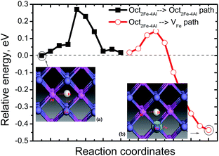
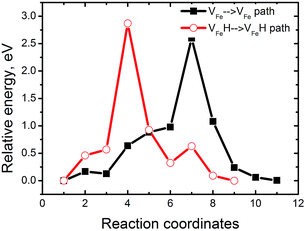
A pre-existing Fe vacancy in bulk FeAl shows that H prefers to occupy the 1NN Oct2Fe–4Al site (1.31 Å off-center to the vacancy shown in Fig. 2) with the lowest formation energy of 0.12 eV. This is higher than previous calculations. However, the energy difference between the H at the 1NN Oct2Fe–4Al site of VFe and the H at the Oct2Fe–4Al site in perfect FeAl coincides with previous DFT calculations (0.38–0.42 eV).28 This signifies that the H atoms are trapped around VFe are thermodynamically feasible.Furthermore, the migration of H atoms was explored to elucidate how H is trapped into VFe. We considered two cases of H diffusion: diffusion within VFe (local diffusion) and from an Oct2Fe–4Al site nearest the VFe (nonlocal diffusion). The local diffusion path does not contribute to the mass H-transport and involves diffusion steps in which hydrogen remains in the VFe. Interestingly, we find that the local diffusion is almost a thermoneutral channel and has a barrier of 0.76–1.18 eV indicating that such diffusion cannot occur at room temperature. However, H migration in the form of non-local diffusion has a barrier of only 0.1 eV along the Oct2Fe–4Al site → VFe path. It is exothermic by −0.45 eV (Fig. 2). At the saddle point of the Oct2Fe–4Al site → VFe path, there are two real frequencies for the adsorbed H at 1567.67 and 1718.47 cm−1. There is an imaginary frequency at 734.10 cm−1. At the starting point, the H has two frequencies at 1566.65 and 1567.46 cm−1. At the end point, H has two frequencies at 858.44 and 1768.59 cm−1. The reverse path proceeds via a higher energy barrier of 0.55 eV. Thus, it is definitely easier for H to be trapped around the VFe than dissociated from the VFeH complex.
Separate from the VFe, H also jumps from one Oct2Fe–4Al site to another with the same diffusion barrier for H in perfect FeAl. In perfect FeAl, the H atom diffuses and involves H atom reorientation around the Fe atom from an Oct2Fe–4Al site to an adjacent one (path Oct2Fe–4Al → Oct2Fe–4Al) by passing through a Fe–Al–Al triangle with a barrier of 0.27 eV (Fig. 2). Real frequencies for adsorbed H at 1567.67 and 1818.47 cm−1 with one imaginary frequency at 728.10 cm−1 are found at the saddle point of Oct2Fe–4Al → Oct2Fe–4Al. At the final point, the H has two frequencies at 1506.46 and 1507.25 cm−1. At the starting point, the H has two frequencies at 1506.80 and 1507.59 cm−1. Our predicted barrier agrees with the H-diffusion barrier of 0.26 eV in bulk FeAl by DFT calculation,23 but these are lower and higher than the experimental barriers of H diffusivity in Fe3Al (0.42 eV)34 and Fe–40Al (0.22 eV),35 respectively.
As discussed above, H trapping around VFe is thermodynamically and kinetically feasible away from the VFe. The H jumps from one Oct2Fe–4Al site to another with a barrier of 0.27 eV. While it is energetically more favorable for H to be in VFe, there is a higher energy barrier exists for Oct2Fe–4Al → Oct2Fe–4Al diffusion. In other words, it is possible that there are a number of events involve H trapping around the VFe at finite temperatures. This forms VFeH complexes before migration from one octahedral interstitial site to another. The next section will focus on multiple H trapping in VFe.
3.3. Stability of VFeHn complexes
To measure how many H atoms that can be trapped in a Fe monovacancy and characterize its corresponding stability, we individually placed several H atoms (up to 10) into the VFe and relaxed the system to search for optimal positions with every H atoms.Inside the Fe vacancy, the H atoms first tend to occupy the six 1NN Oct2Fe–4Al sites of VFe one by one (less than seven atom). Next, the VFe (seventh H atom) and the 2NN OIS2Fe–4Al site has more than 7H atoms. For all configurations considered, the H–H equilibrium distances remain on the magnitude of 1.920–2.785 Å, and the H–Fe distances range from 1.538 to 1.568 Å (Fig. 3).
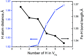 | ||
| Fig. 3 The minimum distance between hydrogen atoms and Fe–H bond length as a function of the number of H atoms in the VFeHn complex. | ||
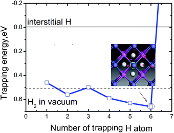
Fig. 4 shows the trapping energy versus the number of H atoms in a Fe monovacancy. Clearly, the trapping energy increases with H incorporation from 0.46 to 0.66 eV. For the first H atom, the trapping energy is 0.46 eV. The second trapped H in the vacancy is energetically 0.07 eV and 0.04 eV higher than the first and third H atoms, respectively. The fourth, fifth, and sixth H atoms are more favorable than the second trapped H. With more than six H atoms, the trapping energy increases sharply and becomes negative, e.g. the seventh trapped H is energetically unfavorable with a trapping energy of −1.73 eV. The VFeH6 complex has highest trapping energy of 0.66 eV. Thus, up to six H can be trapped in a monovacancy, and the corresponding trapping energies are 0.59–0.66 eV for trapping with 4–6 H atoms and 0.46–0.53 eV for trapping with 1–3 H atoms, respectively. The heat of solution for VFeHn, which is the energy compared to H2 molecules in vacuum at ambient conditions, suggests that VFeH2, VFeH4, VFeH5 and VFeH6 formations are completely exothermic for hydrogen and almost zero for VFeH3. The VH formations are slightly endothermic. These indicate that VFeH6 is a major complex at ambient conditions due to the largest negative heat of solution for hydrogen.
The electron density difference of the VFeH6 complex is shown in Fig. 5. The electron transfer to the region around the hydrogen atoms from the neighboring Fe clearly shows that the metal-H hybridization occurs between neighboring Fe atoms and the hydrogen atom (Fig. 5a). In contrast, the H atom has very little effect on the charge distribution of Al atoms (Fig. 5b). This coincides with previous DFT calculations.22 The electron clouds of the negative H flatten in VFe indicating the electron–electron repulsion between the hydrogen atoms.
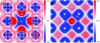 | ||
| Fig. 5 Electron density difference plots of the VFeH6 complex along with four Fe atoms (a) and four Al atoms (a), respectively. | ||
Fig. 3 shows that bond length of Fe–H decreases, and the minimum distance between hydrogen atoms increase with increasing trapped hydrogen atoms. This suggests that the metal-H hybridization of Fe–H prevails, but the repulsion interaction decreases. Consequently, competition between metal-H hybridization and coulombic repulsion makes VFeH6 the major complex at ambient conditions. The local structure of the VFeH6 complex is also shown in Fig. 4. The H atoms clearly occupy the six symmetric 1NN Oct2Fe–4Al sites of the VFe. Our results are strikingly and quantitatively similar to those obtained in simulations of bcc and fcc metals.21,36
3.4. Clusterization of VFeHn complexes
We next investigated the binding preference of two VFeH6 complexes to examine the energetics of vacancy clusters beyond divacancy. The binding energy (Eb) of the two VFeH6 complexes is calculated via30| Eb = E(2H,2V) + Ebulk − 2E(H,V), | (4) |
| Reactants | Products | Eb, eV | |
|---|---|---|---|
| Our work | Ref. 27 | ||
| 2VFe | V2Fe〈111〉 | −0.001 | −0.050 |
| 2VFe | V2Fe〈110〉 | 0.027 | 0.080 |
| 2VFe | V2Fe〈100〉 | −0.012 | 0.120 |
| 2VFeH6 | V2FeH12〈111〉 | 0.000 | — |
| 2VFeH6 | V2FeH12〈110〉 | 0.002 | — |
| 2VFeH6 | V2FeH12〈100〉 | 0.051 | — |
| 2VFeH6 | V2FeH11〈100〉 + HOct2Fe–4Al | 0.048 | — |
For the hydrogen-free FeAl, the Eb of divacancy along 〈111〉, 〈110〉 and 〈100〉 are calculated to be −0.001, 0.027, and −0.012 eV, respectively, suggesting that the Fe vacancies binding is preferred along the 〈110〉 directions. This is partially consistent with previous results showing that 〈100〉 and 〈110〉 divacancy bindings are favorable.27 With H in FeAl, the Eb of the V2FeH12〈110〉 formation is lower than that of V2Fe〈110〉, signifying that hydrogen atoms do not facilitate the 〈110〉 direction-binding processes. However, versus the negative Eb of V2Fe〈100〉, the positive Eb of the V2FeH12〈100〉, and V2FeH11〈100〉 (situation of one H escaping from the unit) suggests that the presence of hydrogen facilitates the 〈100〉 binding processes. Thus, the configurations of V2Fe〈110〉 and V2FeH12〈100〉 complexes can be a directional unit that forms larger V2Fe and V2FeH12 clusters.
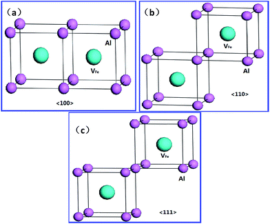
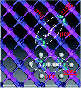
Upon analyzing the periodic crystal structure of B2-FeAl, we concluded that 〈110〉 divacancies are likely to favor not only line clusters along the 〈110〉 direction but also tabular ones along the {110} or {100} planes (Fig. 7). This suggests that there are anisotropic V2Fe clusters, whereas V2FeH12〈100〉 complexes are likely to favor line clusters along the 〈100〉 directions and planar ones along the {100} planes. This maintains hydrogen sites as well as the 〈100〉 binding networks (Fig. 7) suggesting the presence of isotropic V2FeH12 clusters.
The V2FeH12〈100〉 complex is shown in Fig. 8a. A H2〈100〉 molecule forms inside the complex, and the H2 molecule is located at the Oct site between the two vacancies. The H–H bond length is 0.78 Å, which is slightly longer than the ideal H2 molecule bond length of 0.74 Å.25 This is much shorter than the closest distance between hydrogen atoms in the VFeH6 and V2FeH12 complexes (∼1.9 Å shown in Fig. 3). The flattened electron clouds of H atoms in the V2FeH12 complexes (Fig. 8b) are indicative of H–H repulsion. This leads to H2 molecule formation. The H2 bubble nucleation in the Fe atomic divacancy of FeAl is possible in contrast to H2 formation in the monovacancy of pure metal Fe (resulting from the oversaturated hydrogen around the vacancy33), and that in the W and Mo are induced by the isosurface of optimal charge density of the vacancy.21
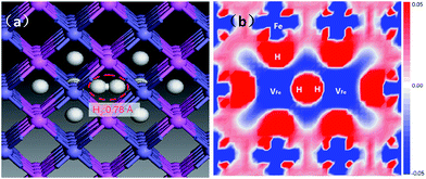 | ||
| Fig. 8 Local structure of V2FeH12〈100〉 cluster-unit. The dashed area denoting the H2 molecule (a), and the corresponding electron density difference is plotted along Fe atoms base (b). | ||
3.5. How VFeHn complexes induce hydrogen embrittlement
These results show the relevance of hydrogenated Fe-vacancy clusters to experimental observed HE in iron aluminides. For hydrogen-free FeAl, Fe vacancies are difficult to merge due to the high barrier of Fe vacancies (Fig. 9). However, the Fe vacancies binding is preferred along the 〈110〉 directions (Table 2), suggesting that the Fe vacancies prefer to grow larger by clusterization of V2Fe〈110〉 units. As shown in Fig. 8, the V2Fe〈110〉 units are likely to favor not only line shaped clusters along the 〈110〉 directions but also tabular ones along the {110} or {100} planes. Moreover, since 〈111〉 are slip directions of bcc metals, the vacancy rows along these directions can be connected with the dislocation motions.30 This likely contributes to fracture along the slip planes. These results can be directly linked with several fractures observed in experiments. In a vacuum, fracture has been shown to occur along {111} for stoichiometric Fe–Al as well as {100} for Fe–40Al and Fe–35Al.3,4When there is H in FeAl, the sharply reduced Ef of a VFe near the interstitial H demonstrates that super-abundant Fe vacancies are easily produced. Meanwhile, H atoms are easily trapped around the Fe-vacancies at finite temperatures (Fig. 2). Thus, the newly generated Fe-vacancies naturally transform into superabundant VFeH6 complexes. Under such high concentrations, the new VFeH6 complexes do not migrate due to the migration-barrier of 2.89 eV (Fig. 9). The VFeH6 complexes prefer to grow larger by clusterization of V2FeH12〈100〉 units, the V2FeH12〈100〉 line-shaped clusters, and tabular clusters in {100} planes (Fig. 7). These likely contribute to fracture or cracking on the cleavage planes. Cracking in FeAl propagates mainly along the {100} plane in the air,3,4 and the edge-oriented Fe3Al single crystals show only slight ductility in the air.5,6
The newly H-induced Fe-vacancies will prefer to grow larger by clusterization of V2Fe〈110〉 units even when H atoms cannot be trapped by VFe above the finite temperatures or under the condition of low H concentrations (Fig. 7). Therefore the anisotropic V2Fe〈110〉 clusterization will be enhanced with corresponding fracture and cracking observed in the H-containing FeAl. This is closely consistent with the experimental conclusion that hydrogen charging decreases the intrinsic ductility even more.1,2
The data show that hydrogen-induced fracture or cracking through isotropic V2FeH12〈100〉 clusters is more relevant to the atomic mechanism of HE in iron aluminides. In the presence of hydrogen, Fe vacancies in iron aluminides naturally generate into a superabundant concentration and trap H atoms to form VFeH6 complexes. Because the new VFeH6 complexes prefer to grow larger by clusterization of V2FeH12〈100〉 units with H2〈100〉 molecules, the 〈100〉 line-shaped and {100} planar clusters can act as the embryos for the formation of cracks and H2 bubbles on the fracture planes. The H concentrations in FeAl will then increase with FeAl-destroying time extensions. This is because of the high reactivity of the Al atoms of FeAl with the moisture in air, which creates hydrogen atoms1 to facilitate further increases in VFeH6 complexes. As the concentrations of VFeH6 complexes increase, they induce even more V2FeH12〈100〉 units, which in turn make the 〈100〉 line-shaped and {100} planar clusters. The inside H2 bubbles grow even bigger and eventually lead to the macroscopic failure observed experimentally. This is the mechanism of isotropic hydrogenated vacancy cluster-induced HE.
4. Conclusions
We investigated H-induced vacancy formation, stability, and clusterization of hydrogen-vacancy complexes (VFeHn) in B2–FeAl based on DFT calculations and thermodynamic formalism. We identified the contributions of vacancy-related processes to HE in iron aluminides.We presented theoretical evidence for the hydrogen-enhanced Fe-vacancy formation in FeAl and provide a scenario in which superabundant Fe-vacancies are naturally generated. The H atoms are more likely trapped around Fe-vacancies than the diffusion from one octahedral interstitial site to another. One Fe-vacancy can accommodate at most six H atoms, and the H atoms occupy six 1NN Oct2Fe–4Al sites of the VFe one by one to form VFeHn complexes. The H–H equilibrium distances in the VFeHn complexes remain on the magnitude of 1.920–2.785 Å, and the H–Fe distances range from 1.538 to 1.568 Å. The corresponding trapping energies are 0.59–0.66 eV for trapping with 4–6 H atoms and 0.46–0.53 eV for trapping with 1–3 H atoms, respectively. The competition between metal-H hybridization and coulombic repulsion makes VFeH6 the major complex under ambient conditions. The VFeH6 complex prefers to grow larger via V2FeH12 unit clusterization along 〈100〉 and {100} with internal H2 molecules. This is closely associated with the experimental observation of cracking along the {100} planes. Thus, a mechanism of isotropic hydrogenated vacancy cluster-induced HE was proposed to show that isotropic V2H12〈100〉 clusters with a linear and planar shape may act as embryos for the formation of cracking, and H2 bubbles. These results offer evidence for the relevance of vacancy-related processes in the atomic-scale mechanism of HE in iron aluminides. This is rarely discussed in the literature.
Of course, our calculations are limited to the study of energetics of hydrogen-vacancy complexes. Kinetic routes for how such complexes evolve to form the cracks will be forthcoming via molecular dynamics and cluster dynamics simulations.
Acknowledgements
We acknowledge financial supports from the National Natural Science Foundation (No. 21471137, 11275175) and National Magnetic Confinement Fusion Science Program (No. 2013GB110006B, 2014GB110006) of China. The authors also thank the computing resource provided by National Supercomputing Center in Shenzhen.Notes and references
- M. Zamanzade, A. Barnoush and C. Motz, Crystals, 2016, 6, 10 CrossRef.
- C. Liu, E. Lee and C. McKamey, Scr. Metall. Mater., 1989, 23, 875 CrossRef CAS.
- M. Nathal and C. Liu, Intermetallics, 1995, 3, 77 CrossRef CAS.
- R. Lynch, K. Gee and L. Held, Scr. Metall. Mater., 1994, 30, 945 CrossRef CAS.
- M. Wittmann, D. Wu, I. Baker, E. George and L. Heatherly, Mater. Sci. Eng., A, 2001, 319, 352 CrossRef.
- H. Saka and T. Ishizaki, Philos. Mag. A, 1996, 73, 173 Search PubMed.
- P. Munroe and I. Baker, Acta Metall. Mater., 1991, 39, 1011 CrossRef CAS.
- R. Oriani and P. Josephic, Acta Metall., 1979, 27, 997 CrossRef CAS.
- S. Lynch, Scr. Mater., 2009, 61, 331 CrossRef CAS.
- P. Ferreira, I. Robertson and H. Birnbaum, Acta Mater., 1999, 47, 2991 CrossRef CAS.
- J. Yan, C. Wang and S. Wang, Phys. Rev. B: Condens. Matter Mater. Phys., 2005, 72, 134108 CrossRef.
- H. Li, M. W. Lie, X. Q. Zhang, J. X. Zhang, X. F. Liu and X. F. Bia, J. Phys. Chem. B, 2008, 112, 15588 CrossRef CAS PubMed.
- M. Wang, X. Huang, Z. Du and Y. Li, Chem. Phys. Lett., 2009, 480, 258 CrossRef CAS.
- G. Zhang, X. Wang, F. Yang, Y. Shi, J. Song and X. Lai, Int. J. Hydrogen Energy, 2013, 38, 7550 CrossRef CAS.
- J. A. White and D. M. Bird, Phys. Rev. B: Condens. Matter Mater. Phys., 1994, 50, 4954 CrossRef CAS.
- B. Delley, J. Chem. Phys., 2000, 113, 7756 CrossRef CAS.
- B. Delley, J. Chem. Phys., 1990, 92, 508 CrossRef CAS.
- B. Delley, Phys. Rev. B: Condens. Matter Mater. Phys., 2002, 66, 155125 CrossRef.
- B. Wang, H. Hou, Y. Luo, L. Yan, Y. Zhao and X. Li, J. Phys. Chem. C, 2011, 115, 13399 CAS.
- C. C. Fu and F. Willaime, Phys. Rev. B: Condens. Matter Mater. Phys., 2005, 72, 064117 CrossRef.
- K. Ohsawa, K. Eguchi, H. Watanabe, M. Yamaguchi and M. Yagi, Phys. Rev. B: Condens. Matter Mater. Phys., 2012, 85, 094102 CrossRef.
- C. L. Fu and G. S. Painter, J. Mater. Res., 1991, 6, 719 CrossRef CAS.
- F. J. Donald and A. E. Carter, Acta Mater., 2010, 58, 638 CrossRef.
- M. Kogachi, T. Haraguchi and S. M. Kin, Intermetallics, 1998, 6, 499 CrossRef CAS.
- L. E. Sutton, Table of Interatomic Distances and Configuration in Molecules and Ions, 2016, http://www.webelements.com/hydrogen/atom_sizes.html Search PubMed.
- M. Fähnle, J. Mayer and B. Meye, Intermetallics, 1999, 7, 315 CrossRef.
- R. Besson, A. Legris and J. Morillo, Phys. Rev. B: Condens. Matter Mater. Phys., 2006, 74, 094103 CrossRef.
- M. Gallouze, A. Kellou, D. Hamoutene, T. Grosdidier and M. Drir, Phys. B, 2013, 416, 1 CrossRef CAS.
- H. E. Schaefer, K. Frenner and R. Würschum, Phys. Rev. Lett., 1999, 82, 984 CrossRef.
- Y. Tateyama and T. Ohno, Phys. Rev. B: Condens. Matter Mater. Phys., 2003, 67, 174105 CrossRef.
- J. Ćížek, F. Lukáč, I. Procházka, M. Vlček, Y. Jirásková, P. Švec and D. Janičkovič, J. Alloys Compd., 2015, 629, 22 CrossRef.
- G. Lu and E. Kaxiras, Phys. Rev. Lett., 2005, 94, 155501 CrossRef PubMed.
- E. Hayward and C. C. Fu, Phys. Rev. B: Condens. Matter Mater. Phys., 2013, 87, 174103 CrossRef.
- X. Cheng and X. Wang, Scr. Mater., 1998, 8, 1505 CrossRef.
- M. Kupka and K. Stepień, Corros. Sci., 2009, 51, 699 CrossRef CAS.
- K. Ohsawa, J. Goto, M. amakami, M. Yamaguchi and M. Yagi, Phys. Rev. B: Condens. Matter Mater. Phys., 2010, 82, 184117 CrossRef.
| This journal is © The Royal Society of Chemistry 2017 |

