 Open Access Article
Creative Commons Attribution 3.0 Unported Licence
Synthesis and optical and electrochemical memory properties of fluorene–triphenylamine alternating copolymer†
Dechao Guoa,
Zhiyao Sunb,
Shuhong Wang *b,
Xuduo Baia,
Laidi Xub,
Qun Yangb,
Ying Xinb,
Rongrong Zhengb,
Dongge Mac,
Xiaofeng Zhaob and
Cheng Wang
 *ab
*ab
aKey Laboratory of Functional Inorganic Material Chemistry, Heilongjiang University, Harbin 150080, P. R. China. E-mail: wangc_93@163.com
bSchool of Chemical Engineering and Materials, Heilongjiang University, Harbin 150080, P. R. China. E-mail: openair@163.com
cSchool of Materials Science and Engineering, South China University of Technology, Guangzhou 510640, P. R. China
First published on 7th February 2017
Abstract
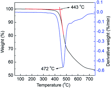
A highly soluble fluorene–triphenylamine conjugated alternating copolymer (PF–TPA) was designed and synthesized under Suzuki coupling reaction conditions in this work. The structure of the copolymer was characterized by Fourier transform infrared (FT-IR) spectroscopy, and hydrogen and carbon nuclear magnetic resonance (1H-NMR, 13C-NMR). The copolymer showed excellent thermal stability, and an onset decomposition temperature up to 443 °C. The optical and electrochemical properties of PF–TPA were investigated by using ultraviolet visible (UV-vis) absorption spectroscopy, photoluminescence (PL) spectroscopy, transient photocurrent responses and cyclic voltammetry (CV). The main absorption peak of PF–TPA appeared at λmax = 382 nm in the thin film and exhibits strong photoluminescence with maximum emission peaks centered at 464 nm in chloroform. The simulation results of the highest occupied molecular orbital (HOMO), lowest unoccupied molecular orbital (LUMO) and energy band gap are −5.04, −2.22 and 2.82 eV, respectively. A non-volatile rewritable flash memory device based on the active layer of PF–TPA was fabricated with the sandwich structure ITO/PF–TPA (102 nm)/Al. The memory device exhibits good electrical bistable resistive switching behavior, with low threshold voltage (VSET ∼ −1.2 V and VRESET ∼ 3.2 V), high ON/OFF current ratio in excess of 103, high stability in retention time up to 104 s and a number of read cycles up to 300 under a read voltage of 2 V in both ON and OFF states. The conductivity mechanism of the ITO/PF–TPA/Al device is discussed. The as-fabricated device exhibited good data retention characteristics, stability and reliability.
1. Introduction
Organic resistive random access memory (ORRAM) materials and devices have attracted a great deal of attention due to the emerging downscaling limits of the conventional inorganic Si-based technologies.1 Generally speaking, ORRAM devices are usually composed of two electrodes and a sandwiched active storage layer. Different from the traditional silicon-based inorganic memory cells, which store data by encoding each electrical circuit as “0” or “1” through discharge and charge, the typical ORRAMs store data as electrical bistability, namely, the memory device exhibits high and low conductivity responses (i.e., ON and OFF states) at the same time under the same external applied voltage.2 Among the reported materials for resistor memory, organic materials have a prominent advantage of good processability and scalability, structure diversity, ultrafast write/read speed, mass data storage capacity, low power consumption, long-term stability, high-mechanical flexibility, simple device structure and the possibility for molecular design through chemical synthesis, making them a promising alternative or complementary technology to the inorganic semiconductor information technology.3 Memory devices based on organic materials have appeared as promising candidates for the next generation of memory devices.In recent years, increasing attention has been paid to the application of organic materials in memory devices on account of their excellent properties. Large amounts of ORRAM devices have been fabricated using various organic materials, including polyimide (PI),4 polyaniline (PAN),5 polyvinylcarbazole (PVK),6 polyfluorene (PF),7 poly(methyl methacrylate) (PMMA),8 polyvinyl alcohol (PVA),9 polystyrene (PS),10 poly(3-hexylthiophene) (P3HT),11 triphenylamine (TPA),12 polyvinylidene fluoride (PVDF),13 as well as combinations of functional components. Among them, it is well-known that the PF and TPA were considered to be the most versatile and promising candidate for memory applications due to their outstanding properties.
PF and its derivatives have been employed in one of the most promising hole-transporting materials for organic light emitting diodes (OLEDs),14 organic field effect transistors (OFETs),15 organic solar cells,16 organic photovoltaics (OPVs),17 electrochromic (EC) devices18, organic memory devices (OMDs),19 and exhibited nonvolatile memory characteristics. Moreover, the PF was chosen as the memory materials due to also its very strong thermal and chemical stability, excellent photoluminescence quantum yields and high carrier mobility properties.
As one of the most efficient hole transporting materials, TPA and its derivatives have been particularly remarkable as a promising candidate for optoelectronic devices due to their low ionization potentials, high electron affinity, excellent electronic and mechanical properties, tridimensional steric and good UV-light harvesting properties.20 Thus, the TPA rich electronic group was introduced into PF, which enhanced the thermal stability, HOMO energy level, the hole-transporting ability and reduce the energy barrier from ITO anode injection hole. Several studies on PF–TPA composite systems using nonvolatile memory devices have been reported so far.21 They have shown excellent nonvolatile memory characteristics, including rewritable flash memory behavior and write-once-read-many times (WORM) memory characteristics. In contrast to the reported literature, the copolymer structure of this content is simple and easily controlled by adjusting the monomer levels used for polymerization. The nitrogen atom of triphenylamine shown a positive electricity when it formed the cation radical. The oxygen atom on the methoxyl group is able to donate electron, and improve the ability of triphenylamine as an electron donor material to provide electron. After the triphenylamine containing methoxyl group was introduced into the main chain of fluorene, it is not only prevent the aggregation effect effectively between the polymer chains, but also improve the HOMO energy level, hole-transporting ability and thermal stability, and reduce the energy barrier from ITO anode injection hole.
In this paper, we first synthesized a conjugated alternating copolymer poly[(9,9-dioctyl)-2,7-fluorene-co-N-4-methoxy-4,4′-triphenylamine] (i.e., PF–TPA) by Suzuki coupling reaction. In this copolymer, the fluorene backbone serves as a conjugated channel for charge carriers, the TPA groups serve as an electron donor and hole transporting material. Then, to evaluate the memory performance of PF–TPA, the copolymer is sandwiched between ITO (indium-tin-oxide) anode and Al cathode as the electroactive layer to fabricate the ITO/PF–TPA/Al resistive switching memory device, and measured the current–voltage (I–V) characteristic curve by a semiconductor device analyzer. The device exhibited a typical bistable electrical switching behavior and nonvolatile rewritable flash memory effect with a low threshold voltage (VSET ∼ −1.2 V, VRESET ∼ 3.2 V), a high ON/OFF current ratio in excess of 103 at −1.2 V and a long retention time of more than 104 s without any degradation. The memory performance tests demonstrated that the presence of ITO/PF–TPA/Al memory device have low mistaking, fast read/write, good stability and reliability characteristics.
2. Experimental
2.1 Materials
Organic solvents and anhydrous sodium carbonate were purchased from Sinopharm Co. Ltd. The solvents used in this study were purified, dried and distilled under dry nitrogen. All of the other chemicals were purchased from Sigma-Aldrich and used with no further purification.2.2 Synthesis of N,N-bis(4-bromophenyl)-4-(1-methylpropyl)-benzenamine (M1)
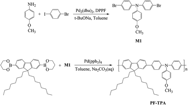
The synthesis of M1 was carried out using a palladium-catalyzed Buchwald–Hartwig coupling reaction. The synthetic route and the chemical structure of the monomer are shown in Scheme 1. The detailed procedure is described as follows: p-anisidine (1.67 g, 13.60 mmol) and 1-bromo-4-iodobenzene (8.46 g, 29.92 mmol) was added to degassed toluene (18 mL) to form a clear solution. Then, tris(dibenzylideneacetone) dipalladium(0) [Pd2(dba)3] (0.125 g, 0.136 mmol), 1,1′-bis(diphenylphosphino) ferrocene (DPPF, 0.30 g, 0.544 mmol) and sodium tert-butoxide (3.92 g, 40.79 mmol) was added to above solution and the mixture was stirred under nitrogen atmosphere at 105 °C for 6 h. After cooled to room temperature, the reaction mixture was purified via extraction, concentration and column chromatography. The final product (M1), a yellow solid, was obtained after drying in vacuo with a yield of 4.87 g (82.8%).The IR spectra of M1 were shown in Fig. S1,† the peak at 1881 and 822 cm−1 can be attributed to the para-substituted benzene of triphenylamine. The peak at 1285 and 1309 cm−1 can be attributed to the stretching vibration of C–N. The peak at 1240 cm−1 can be attributed to the stretching vibration of Ar–O. Moreover, the peak at 1031 cm−1 can be ascribed to the stretching vibration of C–O, and the C–Br stretching vibration are about of 584.21 cm−1, 536.79 cm−1 and 507.14 cm−1.
The 1H-NMR of M1 was shown in Fig. S2.† 1H-NMR (400 MHz, CDCl3) δH (ppm): 3.80 (3H, Ha), 6.83–6.90 (6H, Hc, Hd), 7.00–7.03 (2H, Hb), 7.28–7.31 (4H, He); the 13C-NMR of M1 was shown in Fig. S3.† 13C-NMR (100 MHz, CDCl3), δC (ppm): 55.43 (C1), 114.50 (C3), 114.99 (C9), 124.21 (C4), 127.35 (C7), 132.11 (C8), 139.64 (C5), 146.74 (C6), 156.68 (C2).
2.3 Synthesis of poly[(9,9-dioctyl)-2,7-fluorene-co-N-4-methoxy-4,4′-triphenylamine] (PF–TPA)
The synthesis of PF–TPA was carried out using a palladium-catalyzed Suzuki coupling reaction. The synthetic routes and the chemical structures of the copolymer are shown in Scheme 1. The detailed procedure is described as follows: a mixture of 9,9-dioctylfluorene-2,7-diboronic acid bis(1,3-propanediol) ester (0.5584 g, 1.0 mmol), M1 (0.430 g, 1.0 mmol) was first mixed with degassed toluene (15.6 mL) to form a clear solution. Then, tetrakis(triphenylphosphine) palladium [Pd(PPh3)4] (0.0346 g, 3.0 × 10⁻² mmol) and Na2CO3 solution (15.6 mL, 3.0 mol L−1) was added and the mixture was stirred under nitrogen atmosphere at 105 °C for 48 h. After cooling to room temperature, the reaction mixture was extracted with toluene and deionized water. After removing excess of the solvent under reduced pressure, the concentrated solution was added to the cold methanol to give a precipitate. Then, the precipitate was further purified by extraction with acetone for 36 h in a Soxhlet apparatus to remove the rest of the monomers and Pd catalyst. After vacuum drying treatment, the obtained product was characterized by IR spectroscopy, NMR spectroscopy with 1H and 13C probes and TGA analysis. In addition, the optical and electrochemical properties of the polymer were also investigated.FTIR spectroscopy was used to analyze the presence of bonds in PF–TPA. Fig. S4† shows FTIR spectra of PF–TPA, which was tested by Magna-IR560 infrared spectrometers. It exhibits a characteristic absorption peak at 2926 cm−1. This peak is attributed to the C–H stretching mode, which probably is associated with hydrocarbon contamination in the spectrometer. Furthermore, the broad absorption peak at 1506 and 1462 cm−1 can be attributed to the stretching of C![[double bond, length as m-dash]](https://www.rsc.org/images/entities/char_e001.gif) C and C–C bonds. Moreover, the peak at 1317 cm−1 can be ascribed to the stretching vibration of C–N, and the C–O stretching vibration is about of 1242 cm−1.
C and C–C bonds. Moreover, the peak at 1317 cm−1 can be ascribed to the stretching vibration of C–N, and the C–O stretching vibration is about of 1242 cm−1.
The 1H-NMR of PF–TPA was shown in Fig. S5.† 1H-NMR (400 MHz, CDCl3) δH (ppm): 0.74–0.81 (t, 6H, Hp), 1.07–1.26 (m, J = 7.9 Hz, 24H, Hj, Hk, Hl, Hm, Hn, Ho), 2.01–2.35 (4H, Hi), 3.84 (s, 3H, Ha), 6.98–6.92 (d, J = 8.4 Hz, 2H, Hc), 7.19–7.21 (d, 6H, Hb), 7.56–7.58 (m, J = 9.2 Hz, 8H, He, Hg, Hh), 7.73–7.75 (d, J = 7.8 Hz, 2H, Hf).
The 13C-NMR of PF–TPA was shown in Fig. S6.† 13C-NMR (100 MHz, CDCl3), δC (ppm): 155.41 (C2), 150.60 (C10), 146.15 (C6), 139.42 (C15), 138.67 (C12), 138.35 (C5), 134.09 (C11), 126.69 (C8), 126.42 (C14), 124.47 (C13), 122.04 (C4), 119.84 (C9), 118.88 (C7), 113.87 (C3), 54.47 (C1), 39.46 (C16), 30.75 (C17), 29.85 (C22), 29.03 (C19), 28.20 (C20), 28.19 (C21), 22.81 (C18), 21.56 (C23), 13.04 (C24).
GPC analysis of the PF–TPA was performed on a Malvern instrument connected with one refractive index detector (Viscotek-VE3580-RIDETECTOR) at a flow rate of 0.8 mL min−1 at 35 °C using THF solution and calibrated with polystyrene standard. The number-average molecular weight (Mn), weight-average molecular weight (Mw), polydispersity (PDI) and the average degree of polymerization (n) of PF–TPA was determined to be 23![[thin space (1/6-em)]](https://www.rsc.org/images/entities/char_2009.gif) 000, 32
000, 32![[thin space (1/6-em)]](https://www.rsc.org/images/entities/char_2009.gif) 500, 1.41 and 34.8, respectively.
500, 1.41 and 34.8, respectively.
2.4 Fabrication and measurement of the memory device
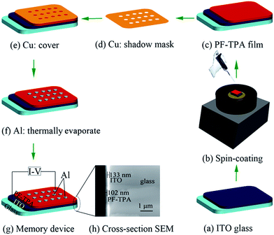
The schematic of the ITO/PF–TPA/Al memory device is depicted in Fig. 1. The typical sandwiched configuration memory device is fabricated using the following procedure. The indium tin oxide (ITO) conductive glass substrates of dimensions 2 cm × 1 cm (sheet resistance R□ = 6–9 Ω □−1) was employed as the bottom electrode and precleaned sequentially with the detergent, deionized water, acetone, isopropanol and methanol in an ultrasonic bath for 30 min, respectively. Then they were dried in a vacuum oven at 60 °C overnight. The PF–TPA was dissolved in toluene solvent (5 mg mL−1) with a strongly magnetic stirring at room temperature for 24 h. After that, it was filtered through a polytetrafluoroethylene (PTFE) membrane microfilter with a pore size of 0.2 μm.Then, the PF–TPA solution as an active polymer layer was spin-coated onto the ITO glass substrate at a spinning speed of 900 rpm for 15 s and then 3000 rpm for 45 s, and dried in a vacuum oven at 70 °C for 5 h to remove the residual solvent. Parameter settings for this procedure were beneficial to form uniform and smooth films. In the end, the Al top electrode layer was deposited with a thickness of 300 nm onto the organic film surface via vacuum thermally evaporated under high vacuum of 10−7 Torr through a shadow mask. The obtained device cells diameter is about 0.2 mm.
The cross-section scanning electron microscope (SEM) image of the device based on PF–TPA before the evaporation of the Al electrode is shown in Fig. 1h, from the left to right show PF–TPA storage layer, ITO film and glass substrate, respectively. The thickness of the PF–TPA copolymer film can be judged as 102 nm from this image as measured by SEM.
2.5 Measurements
The IR spectra were recorded on Magna-IR560 infrared spectrometers with KBr pellet from 400–4000 cm−1. Nuclear magnetic resonance (NMR) spectra were recorded on a Bruker 400 spectrometer at a resonance frequency of 400 MHz for 1H and 13C NMR in deuterated chloroform. Thermal properties of the samples were measured using a Netzsch STA409 thermogravimetric analyzer at a heating rate of 10 °C min−1 from 50 °C to 750 °C. The UV-vis absorption spectra measurements were carried out with a 756 CRT UV-Vis spectrophotometer. The PL emission and excitation spectra were obtained with a FLSP 920 full-featured fluorescence spectrometer from 350–625 nm. Cyclic voltammetry was performed on an ALS630B electrochemical analyzer with deaerated acetonitrile containing tetrabutylammonium perchlorate (TBAP, 0.1 M) as the electrolyte, a platinum wire as a counter electrode, an Ag/AgCl as a reference electrode at a scan rate of 50 mV s−1. The current–voltage (I–V) characteristic of the memory device was performed by a Keithley 4200-SCS semiconductor parameter analyzer under the ambient condition. During the measurement, the bottom electrode (ITO) was ground, and a bias voltage (from −6.0 V to +6.0 V) was applied between the top (Al) and bottom (ITO) electrodes at a scan rate of 500 mV s−1, and the compliance current was set to 0.1 A to avoid breakdown of the device.3. Results and discussion
3.1 Characterization of the copolymer PF–TPA
| Eg = 1240/λon-set | (1) |
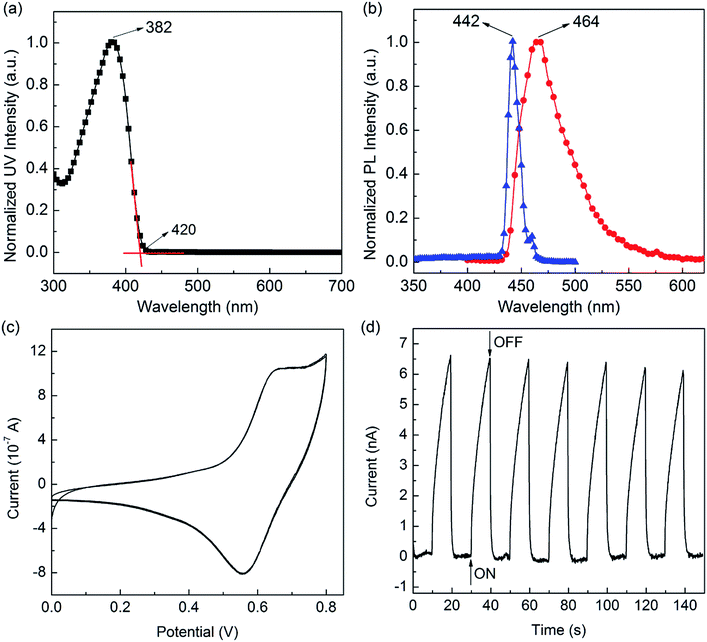
By applying 442 nm as excitation wavelength, the copolymer exhibits very strong blue fluorescence with maximum emission peak centered at 464 nm (Fig. 3b), in the solid thin films. The copolymer solid film will appear the π–π conjugate accumulation and molecular chains aggregation due to the large number of benzene group in molecule. It makes the molecular energy gap decreases. Eventually, the emission wavelength showed a red-shift phenomenon. The fluorescence quantum yields (Φf = 0.61) of copolymer in THF solvents were measured by using quinine sulfate dissolved in 0.5 M sulfuric acids as reference standard (Φ = 0.546).
As a result, the HOMO energy value (EHOMO) of PF–TPA was experimentally calculated according to the eqn (2), provided that the standard ferrocene potential in the CV supporting electrolyte and the Fermi level of ferrocene at 4.8 eV below the vacuum level are known23
| EHOMO = −[Eonset − Eox(ferrocene)] − 4.8 eV | (2) |
In our electrochemical experiments, ferrocene exhibits an oxidation peak with an onset of 0.38 V versus Ag/AgCl. The LUMO energy value (ELUMO) level was estimated from the EHOMO and Eoptg using eqn (3), due to the accurate reduction curves could be hardly obtained.
| ELUMO = EHOMO + Eoptg | (3) |
Thus, the EHOMO, ELUMO and Eoptg of PF–TPA were calculated to be −4.96 eV, −2.01 eV and 2.95 eV, respectively. Due to the suitable thermal stabilities, EHOMO value and reversible electrochemical behaviors, the PF–TPA can be used potential candidates as hole-transporting and blue light-emitting materials in emitting devices.
As shown in Fig. 3d, photocurrent transient measurements show that the current generated by the PF–TPA can be in “On” or “Off” state by turning on and off the xenon lamp at 0.5 V applied voltage. When the PF–TPA was illuminated by xenon lamp, the current increased sharply to the saturated current within 10 s. When the xenon lamp was turned off, the current decreased immediately back to minimum value, i.e., recovered to the initial value in the dark. The transient photocurrent curve shows reproducibility for at least 7 times without significant change, indicating that the copolymer has a good stability and the capacity of quick response.
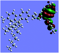
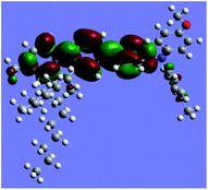
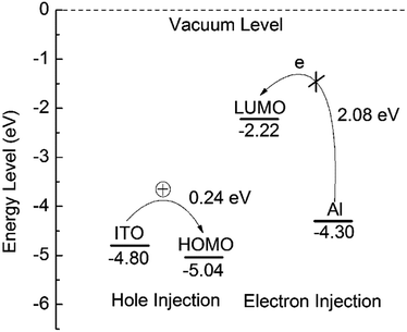
The density functional theory (DFT) calculations were performed using the hybrid functional B3LYP with the basis set 6-31G for PF–TPA. First, the electronic ground state was optimized for copolymer via DFT. Then, the corresponding excitation energies were calculated, the corresponding simulation results are presented in Table 1. The electronic cloud function of the HOMO is distributed throughout TPA part of the PF–TPA, which is good to get higher hole mobility. The electronic cloud of the LUMO is mainly localized on the fluorene portion. The HOMO, LUMO, and band gaps simulated from the B3LYP/6-31G model chemistry are −5.04 eV, −2.22 eV and 2.82 eV, respectively. The band gap (Eg = 2.82 eV) calculated by the molecular simulation is basically consistent with the optical band gap (Eoptg = 2.95 eV) estimated by the CV and UV-vis absorption onset data. The slight deviation may be caused by the affection of the molecular interaction, molecular structure and solvation process. In addition, the theoretical calculation results are based on the monomer, whereas the actual experimental measured results are in view of the entire polymer.
3.2 Characterization of the memory device based on PF–TPA
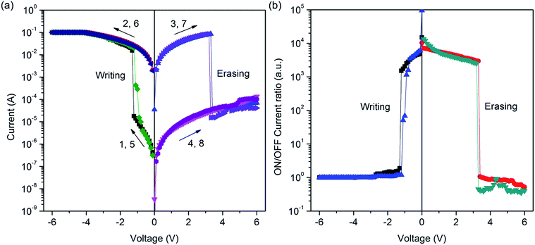 | ||
| Fig. 4 (a) I–V curves of ITO/PF–TPA/Al device. (b) Relationship between the ON/OFF ratio of current and the applied voltage for ITO/PF–TPA/Al device. | ||
Fig. 4b shows the relationship between the ON/OFF current ratio and the voltage for ITO/PF–TPA/Al device. It is observed that the ON/OFF current ratio is more than 103 in the threshold voltage of −1.2 V. The ON/OFF current ratio in the present device is high enough to promise a low misreading rate through the precise control of the ON and OFF states during the storage procedure.
Fig. 5a shows the result of a retention performance for the electrical bistable memory device ITO/PF–TPA/Al. The stability of the ITO/PF–TPA/Al sandwich memory device was measured continuously by using a constant reading voltage of 2 V in ambient atmosphere at room temperature. Here, we fixed the read voltage at 2 V because it was not close to the threshold voltage and had the stable performance. The ON/OFF current ratio of 3 × 10³ can be maintained and no obvious degradation is observed during the test period of at least 3 h, indicating that the copolymer material and electrode/copolymer interfaces have excellent stability.
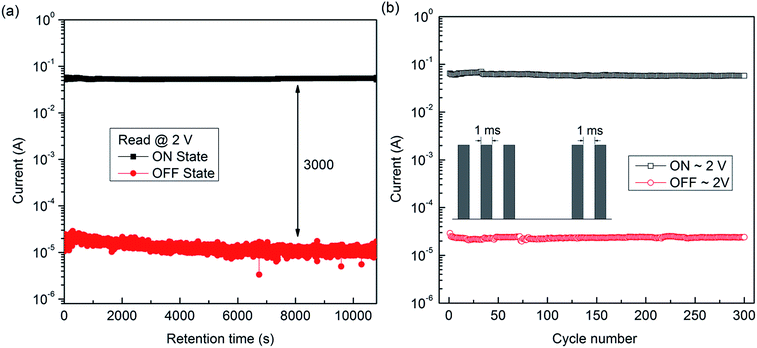 | ||
| Fig. 5 (a) Retention performance of ITO/PF–TPA/Al device. (b) Stimulus effect of read pulses on the ON and OFF states of the ITO/PF–TPA/Al device. The inset shows the pulse shapes in the measurement. | ||
As shown in Fig. 5b, the current density for the ON and OFF states remained unchanged even after more than 300 read cycles (pulse period = 2 ms, pulse width = 1 ms), indicating that both ON and OFF states were insensitive to read cycles. All these results reveal that the prototype memory device based on PF–TPA copolymer has a potential application for data storage.
![[thin space (1/6-em)]](https://www.rsc.org/images/entities/char_2009.gif) I–log
I–log![[thin space (1/6-em)]](https://www.rsc.org/images/entities/char_2009.gif) V curve has a straight line region with a slope of 1.06 (set) and 1.08 (reset), which were very close to 1. This means that the I–V data for the ON state could be satisfactorily fit using the ohmic conduction model (I ∝ V). Moreover, the current levels of the devices in the ON state was found to be independent of the device cell size, which is indicative of the heterogeneous localized filament formation28
V curve has a straight line region with a slope of 1.06 (set) and 1.08 (reset), which were very close to 1. This means that the I–V data for the ON state could be satisfactorily fit using the ohmic conduction model (I ∝ V). Moreover, the current levels of the devices in the ON state was found to be independent of the device cell size, which is indicative of the heterogeneous localized filament formation28
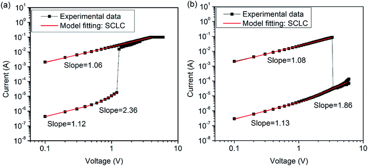 | ||
| Fig. 6 Linear fitting and corresponding slopes of the I–V curves of ITO/PF–TPA/Al device. (a) Set process. (b) Reset process. | ||
On the other hand, the log![[thin space (1/6-em)]](https://www.rsc.org/images/entities/char_2009.gif) I–log
I–log![[thin space (1/6-em)]](https://www.rsc.org/images/entities/char_2009.gif) V plot shows an ohmic conduction behavior under a low voltage region ((a) ≤0.5 V; (b) <1.0 V) for the OFF state of the device, namely, a linear proportion (with the slope of 1.12 for set process and 1.13 for reset process). Then, the log
V plot shows an ohmic conduction behavior under a low voltage region ((a) ≤0.5 V; (b) <1.0 V) for the OFF state of the device, namely, a linear proportion (with the slope of 1.12 for set process and 1.13 for reset process). Then, the log![[thin space (1/6-em)]](https://www.rsc.org/images/entities/char_2009.gif) I–log
I–log![[thin space (1/6-em)]](https://www.rsc.org/images/entities/char_2009.gif) V plot gradually changes to the Child's law region (with the slope of 2.36 for set process, and 1.86 for reset process) at the high voltage region, for which the current is proportional to the square of the voltage (I ∝ V2). This data analysis suggests that the trap-limited space-charge limited current (SCLC) conduction mechanism is probably the main conduction mechanism in the OFF state.29
V plot gradually changes to the Child's law region (with the slope of 2.36 for set process, and 1.86 for reset process) at the high voltage region, for which the current is proportional to the square of the voltage (I ∝ V2). This data analysis suggests that the trap-limited space-charge limited current (SCLC) conduction mechanism is probably the main conduction mechanism in the OFF state.29
Above results suggest that the excellent non-volatile memory behavior of the PF–TPA film was governed by trap-limited SCLC and local filament formation.
When the reverse applied voltage increases above the reset voltage (approached 3.2 V), the injected charge exceeds the capacity of the filament, and the excess current generates heat. At the same time, the repulsive coulombic interactions among the trapped charges in the PF–TPA active layer and the Al electrode may be caused by the excess current. The heat and Coulomb repulsion can rupture the filament formed in the SET process, switching the device returns to its initial OFF state30 (i.e., “erasing” process).
4. Conclusions
In summary, we have successfully synthesized the conjugated alternating copolymer (PF–TPA) by Suzuki coupling reaction. This active material exhibited excellent thermal stability, optical properties as well as electric characteristics. Then, we fabricated the non-volatile electrical bistable resistive memory devices utilizing organic semiconductor thin film layer (PF–TPA) by using a spin-coating method. Based on the experimental results, the as-fabricated ITO/PF–TPA/Al sandwich memory device exhibited typical electrical conductance switching behavior and non-volatile rewritable flash memory effects. The device has a great ON/OFF state current ratio (greater than 103 at −1.2 V) and a low threshold voltage (VSET ∼ −1.2 V and VRESET ∼ 3.2 V), that promise a low misreading rate and fast response, respectively. Moreover, the retention characteristic test showed that the ITO/PF–TPA/Al device is very stable under a constant voltage stress of 2 V for up to 3 h. And no degradation in current was observed for the ON and OFF states after more than 300 continuous read cycles at 2 V pulse. In principle, the results demonstrate that PF–TPA is promising and reliable for resistive switching devices for next generation high density storage media.Acknowledgements
The authors are grateful to the support of the National Science Foundation of China (51527804, 51473056, 51503058, 51573015, 61471159), and Post-graduate Innovative Research Program of Heilongjiang University (YJSCX2015-080HLJU).Notes and references
- (a) G. F. Tian, S. L. Qi, F. Chen, L. Shi, W. P. Hu and D. Z. Wu, Appl. Phys. Lett., 2011, 98, 203302 CrossRef; (b) P. Wang, S. J. Liu, Z. H. Lin, X. C. Dong, Q. Zhao, W. P. Lin, M. D. Yi, S. H. Ye, C. X. Zhu and W. Huang, J. Mater. Chem., 2012, 22, 9576–9583 RSC; (c) C. J. Chen, Y. C. Hu and G. S. Liou, Chem. Commun., 2013, 49, 2804–2806 RSC.
- (a) Y. Q. Li, H. H. Xu, X. Tao, K. J. Qian, S. Fu, S. J. Ding and Y. Z. Shen, Polym. Int., 2011, 60, 1679–1687 CrossRef CAS; (b) L. Shi, N. F. Jia, L. S. Kong, S. L. Qi and D. Z. Wu, Macromol. Chem. Phys., 2014, 215, 2374–2388 CrossRef CAS; (c) W. B. Zhang, C. Wang, G. Liu, J. Wang, Y. Chen and R. W. Li, Chem. Commun., 2014, 50, 11496–11499 RSC.
- (a) T. Kurosawa, T. Higashihara and M. Ueda, Polym. Chem., 2013, 4, 16–30 RSC; (b) C. Y. Zhang, J. H. He, C. J. Lu, Q. F. Gu, L. X. Wu, Q. Liu, H. Li, Q. F. Xu and J. M. Lu, Polymer, 2015, 70, 343–350 CrossRef CAS; (c) Y. Zhou, S. T. Han, Y. Yan, L. Zhou, L. B. Huang, J. Q. Zhuang, P. Sonar and V. A. L. Roy, Sci. Rep., 2015, 5, 10683 CrossRef CAS PubMed.
- (a) J. J. Kim, B. Cho, K. S. Kim, T. Lee and G. Y. Jung, Adv. Mater., 2011, 23, 2104–2107 CrossRef CAS PubMed; (b) Y. Q. Li, Y. Y. Chu, R. C. Fang, S. J. Ding, Y. L. Wang, Y. Z. Shen and A. M. Zheng, Polymer, 2012, 53, 229–240 CrossRef CAS; (c) Y. Kim, D. Yoo, J. Jang, Y. Song, H. Jeong, K. Cho, W. T. Hwang, W. Lee, T. W. Kim and T. Lee, Org. Electron., 2016, 33, 48–54 CrossRef CAS.
- D. Wei, J. K. Baral, R. Österbacka and A. Ivaska, J. Mater. Chem., 2008, 18, 1853–1857 RSC.
- (a) S. G. Hahm, T. J. Lee, D. M. Kim, W. Kwon, Y. G. Ko, T. Michinobu and M. Ree, J. Phys. Chem. C, 2011, 115, 21954–21962 CrossRef CAS; (b) A. Suresh, G. Krishnakumar and M. A. G. Namboothiry, Phys. Chem. Chem. Phys., 2014, 16, 13074–13077 RSC.
- (a) B. Lei, W. L. Kwan, Y. Shao and Y. Yang, Org. Electron., 2009, 10, 1048–1053 CrossRef CAS; (b) C. Chakraborty, M. K. Bera, U. Rana and S. Malik, Chem. Commun., 2015, 51, 13123–13126 RSC.
- (a) D. I. Son, T. W. Kim, J. H. Shim, J. H. Jung, D. U. Lee, J. M. Lee, W. Il Park and W. K. Choi, Nano Lett., 2010, 10, 2441–2447 CrossRef CAS PubMed; (b) S. L. Qi, H. Iida, L. L. Liu, S. Irle, W. P. Hu and E. Yashima, Angew. Chem., Int. Ed., 2013, 52, 1049–1053 CrossRef CAS PubMed.
- Y. M. Sun, J. G. Lu, C. P. Ai and D. Z. Wen, Phys. Chem. Chem. Phys., 2016, 18, 11341–11347 RSC.
- (a) C. L. Liu, J. C. Hsu, W. C. Chen, K. Sugiyama and A. Hirao, ACS Appl. Mater. Interfaces, 2009, 1, 1974–1979 CrossRef CAS PubMed; (b) J. E. Park, J. H. Eom, T. Lim, D. H. Hwang and S. Pyo, J. Polym. Sci., Part A: Polym. Chem., 2012, 50, 2188–2193 CrossRef CAS.
- (a) T. W. Kim, D. F. Zeigler, O. Acton, H. L. Yip, H. Ma and A. K. Y. Jen, Adv. Mater., 2012, 24, 828–833 CrossRef CAS PubMed; (b) L. Zhang, Y. Li, J. Shi, G. Q. Shi and S. K. Cao, Mater. Chem. Phys., 2013, 142, 626–632 CrossRef CAS.
- (a) D. M. Kim, S. Park, T. J. Lee, S. G. Hahm, K. Kim, J. C. Kim, W. Kwon and M. Ree, Langmuir, 2009, 25, 11713–11719 CrossRef CAS PubMed; (b) J. H. Wu, H. J. Yen, Y. C. Hu and G. S. Liou, Chem. Commun., 2014, 50, 4915–4917 RSC.
- A. Thakre, H. Borkar, B. P. Singha and A. Kumar, RSC Adv., 2015, 5, 57406–57413 RSC.
- (a) A. Garcia, R. C. Bakus II, P. Zalar, C. V. Hoven, J. Z. Brzezinski and T. Q. Nguyen, J. Am. Chem. Soc., 2011, 133, 2492–2498 CrossRef CAS PubMed; (b) K. M. Schelkle, M. Bender, K. Jeltsch, T. Buckup, K. Mîllen, M. Hamburger and U. H. F. Bunz, Angew. Chem., Int. Ed., 2015, 54, 14545–14548 CrossRef CAS PubMed.
- (a) S. H. Wang, M. Kappl, I. Liebewirth, M. Müller, K. Kirchhoff, W. Pisula and K. Müllen, Adv. Mater., 2012, 24, 417–420 CrossRef CAS PubMed; (b) Y. X. Zhu, Z. H. Chen, Y. Yang, P. Cai, J. W. Chen, Y. Y. Li, W. Yang, J. B. Peng and Y. Cao, Org. Electron., 2015, 23, 193–198 CrossRef CAS.
- (a) S. H. Oh, S. I. Na, J. Jo, B. Lim, D. Vak and D. Y. Kim, Adv. Funct. Mater., 2010, 20, 1977–1983 CrossRef CAS; (b) E. W. Zhu, J. F. Hai, Z. X. Wang, B. Ni, Y. H. Jiang, L. Y. Bian, F. J. Zhang and W. H. Tang, J. Phys. Chem. C, 2013, 117, 24700–24709 CrossRef CAS.
- (a) C. R. McNeill, J. J. M. Halls, R. Wilson, G. L. Whiting, S. Berkebile, M. G. Ramsey, R. H. Friend and N. C. Greenham, Adv. Funct. Mater., 2008, 18, 2309–2321 CrossRef CAS; (b) D. C. Watters, H. Yi, A. J. Pearson, J. Kingsley, A. Iraqi and D. Lidzey, Macromol. Rapid Commun., 2013, 34, 1157–1162 CrossRef CAS PubMed.
- (a) B. Y. Hsieh and Y. Chen, J. Polym. Sci., Part A: Polym. Chem., 2009, 47, 833–844 CAS; (b) L. P. Lu, D. Kabra, K. Johnson and R. H. Friend, Adv. Funct. Mater., 2012, 22, 144–150 CrossRef CAS.
- (a) T. W. Kim, S. H. Oh, H. Choi, G. Wang, H. Hwang, D. Y. Kim and T. Lee, Appl. Phys. Lett., 2008, 92, 253308 CrossRef; (b) H. C. Wu, A. D. Yu, W. Y. Lee, C. L. Liu and W. C. Chen, Chem. Commun., 2012, 48, 9135–9137 RSC.
- Y. Ma, X. B. Cao, G. Li, Y. Q. Wen, Y. Yang, J. X. Wang, S. X. Du, L. M. Yang, H. J. Gao and Y. L. Song, Adv. Funct. Mater., 2010, 20, 803–810 CrossRef CAS.
- (a) C. Q. Ye, Q. Peng, M. Z. Li, J. Luo, Z. M. Tang, J. Pei, J. M. Chen, Z. G. Shuai, L. Jiang and Y. L. Song, J. Am. Chem. Soc., 2012, 134, 20053–20059 CrossRef CAS PubMed; (b) B. Zhang, Y. Chen, G. Liu, L. Q. Xu, J. N. Chen, C. X. Zhu, K. G. Neoh and E. T. Kang, J. Polym. Sci., Part A: Polym. Chem., 2012, 50, 378–387 CrossRef CAS; (c) Y. G. Ko, D. M. Kim, K. Kim, S. Jung, D. Wi, T. Michinobu and M. Ree, ACS Appl. Mater. Interfaces, 2014, 6, 8415–8425 CrossRef CAS PubMed; (d) H. B. Ye, G. F. Tian, L. Shi, S. L. Qi and D. Z. Wu, Eur. Polym. J., 2015, 63, 45–57 CrossRef CAS.
- (a) G. S. Liou, S. M. Lin and H. J. Yen, Eur. Polym. J., 2008, 44, 2608–2618 CrossRef CAS; (b) A. Bolognesi, P. Betti, C. Botta, S. Destri, U. Giovanella, J. Moreau, M. Pasini and W. Porzio, Macromolecules, 2009, 42, 1107–1113 CrossRef CAS; (c) K. L. Wang, M. K. Leung, L. G. Hsieh, C. C. Chang, K. R. Lee, C. L. Wu, J. C. Jiang, C. Y. Tseng and H. T. Wang, Org. Electron., 2011, 12, 1048–1062 CrossRef CAS.
- (a) Y. Lin, T. L. Ye, Y. Chen, D. G. Ma, Z. K. Chen, Y. F. Dai and Y. X. Li, J. Polym. Sci., Part A: Polym. Chem., 2010, 48, 5930–5937 CrossRef CAS; (b) L. Li, T. Q. Hu, C. R. Yin, L. H. Xie, Y. Yang, C. Wang, J. Y. Lin, M. D. Yi, S. H. Ye and W. Huang, Polym. Chem., 2015, 6, 983–988 RSC.
- (a) J. W. Cai, H. J. Niu, C. Wang, L. N. Ma, X. D. Bai and W. Wang, Electrochim. Acta, 2012, 76, 229–241 CrossRef CAS; (b) C. N. Chuang, C. Y. Chang, C. L. Chang, Y. X. Wang, Y. S. Lin and M. Leung, Eur. Polym. J., 2014, 56, 33–44 CrossRef CAS.
- P. Mourya, S. Banerjee and M. M. Singh, Corros. Sci., 2014, 85, 352–363 CrossRef CAS.
- (a) A. A. Nazeer, N. K. Allam, A. S. Fouda and E. A. Ashour, Mater. Chem. Phys., 2012, 136, 1–9 CrossRef CAS; (b) M. Özcan, I. Dehri and M. Erbil, Appl. Surf. Sci., 2004, 236, 155–164 CrossRef.
- (a) D. B. Hmamou, R. Salghi, A. Zarrouk, M. R. Aouad, O. Benali, H. Zarrok, M. Messali, B. Hammouti, M. M. Kabanda, M. Bouachrine and E. E. Ebenso, Ind. Eng. Chem. Res., 2013, 52, 14315–14327 CrossRef CAS; (b) M. Akhtaruzzaman, H. N. M. E. Mahmud, A. Islam, A. E. Shafei, M. R. Karim, K. Sopian, L. Y. Han and Y. Yamamoto, Mater. Chem. Phys., 2013, 142, 82–86 CrossRef CAS.
- (a) K. Kim, H. J. Yen, Y. G. Ko, C. W. Chang, W. Kwon, G. S. Liou and M. Ree, Polymer, 2012, 53, 4135–4144 CrossRef CAS; (b) T. J. Lee, Y. G. Ko, H. J. Yen, K. Kim, D. M. Kim, W. Kwon, S. G. Hahm, G. S. Liou and M. Ree, Polym. Chem., 2012, 3, 1276–1283 RSC.
- (a) H. Baek, C. Lee, J. Park, Y. Kim, B. Koo, H. J. Shin, D. Y. Wang and J. H. Cho, J. Mater. Chem., 2012, 22, 4645–4651 RSC; (b) Y. J. Huang, S. C. Chao, D. H. Lien, C. Y. Wen, J. H. He and S. C. Lee, Sci. Rep., 2016, 6, 23945 CrossRef CAS PubMed.
- B. L. Hu, C. Y. Wang, J. Zhang, K. Qian, P. S. Leea and Q. C. Zhang, RSC Adv., 2015, 5, 77122–77129 RSC.
Footnote |
| † Electronic supplementary information (ESI) available. See DOI: 10.1039/c6ra28154k |
| This journal is © The Royal Society of Chemistry 2017 |

