 Open Access Article
Silver nanoparticle-immobilized porous POM/PLLA nanofibrous membranes: efficient catalysts for reduction of 4-nitroaniline†
Yuanyuan Liang,
Chuanxin Lin,
Jipeng Guan and
Yongjin Li*
College of Material, Chemistry and Chemical Engineering, Hangzhou Normal University, Hangzhou, 310036, China. E-mail: yongjin-li@hznu.edu.cn; Fax: +86 571 28867899; Tel: +86 57128867026
First published on 23rd January 2017
Abstract
In this study, porous polyoxymethylene/poly(L-lactide) (POM/PLLA) nanofibrous membranes (NFMs) immobilized with silver nanoparticles (Ag NPs) are obtained via the technique of electrospinning followed by the method of seed-mediated silver electroless depositing. POM/PLLA NFMs with a high surface area were functionalized with amino groups acting as anchors so that the Ag NPs with an average diameter of about 7.6 nm were well-dispersed on the fibers of POM/PLLA NFMs. The POM/PLLA NFMs with a Ag loading content of 20.7 wt% exhibit a high catalytic rate constant of 21.25 × 10⁻³ s−1. Furthermore, the catalytic NFMs exhibit an excellent recoverable and cyclic feature that give a more than 99% conversion of 4-nitroaniline (4-NA) after 4 reaction cycles. The continuous conversion rate of 4-NA can remain higher than 90% even after 4 hours of running time at a flow rate of 0.4 mL min−1. Therefore, the abovementioned approach based on POM/PLLA NFMs provides a useful platform for the fabrication of noble metal nanocatalysts, which could be used as the efficient catalysts in various applications.
1 Introduction
Noble metal nanoparticles (NPs) continue to receive immense scientific and technological interest in applications including, but not limited to, optoelectronics,1,2 sensing,3–5 biomedicine,6–10 and catalysis.11–13 In particular, silver (Ag) NPs (Ag NPs) have been proved to be promising candidates for use in catalysis. For catalytic applications, especially for liquid-phase treatments, it is necessary to immobilize Ag NPs onto a support material that can be easily separated from the liquid phase to make the metal NPs easily recyclable and reusable. Likewise, the support material should be able to effectively stabilize the NPs and prevent them from agglomeration caused by interparticle interactions. In recent years, much effort has been focused on the development of effective strategies to incorporate NPs within a support material. Usually, the nanofibrous membranes (NFMs) are considered as efficient supporting materials for catalysis since they can offer high permeability due to their large specific surface area, high fiber aspect ratio and high porosity. Therefore, many studies have focused on the fabrication of NFMs via electrospinning because it is a simple and cost-effective method to produce fibrous mats in the micro to nanometer fiber diameter range, and has a controllable composition and porous structure.14,15 However, immobilization of metal nanoparticles with well-controlled dispersion, size, and geometry on the surface of a highly porous electrospun substrate poses a challenge. As a consequence, substantial effort has been directed towards uniform inclusions of nanoparticles inside the matrix of electrospun fibers, i.e., fabricating nanocomposite fibers, rather than surface-localized particles. Frequently, presynthesized NPs are directly dispersed in the polymeric solution prior to electrospinning.16–18 However, it is extremely difficult to disperse NPs homogeneously into the NFMs by these methods because of the easy agglomeration of nanoparticles and the high viscosity of polymer solution. What's more, direct incorporation of the NPs into the polymer solution prior the electrospinning process usually leads to a decrease of the catalytic activity, most probably due to the leaching of active species. To solve this problem, control of the deposition or synthesis of uniform NPs on electrospun nanofibers has been developed. For instance, Carlber et al. fabricated silver nanoparticles on imide cleavage polyimide nanofibers by chemical and thermal reduction of silver nitrate absorbed on the surface of fibers.19 Another example is the immobilization of gold nanoparticles on poly(vinyl alcohol) nanofibers functionalized with 3-mercaptopropyltrimethoxysilane through gold–sulfur bonding interactions.20 Therefore, to create NP-immobilized hybrid NFMs, it is a prerequisite to prepare functionalized nanofibers, which should possess the functional groups allowing for effective chemical or physical interactions with the metal ions or formed NPs.Recently, we have succeeded in preparing novel three dimensional interpenetrated bulk membranes21,22 and NFMs23 based on the polyoxymethylene/poly(L-lactide) (POM/PLLA), in which POM and poly(L-lactide) (PLLA) form a co-continuous structure, and the etching of PLLA induces the formation of the internal nanochannels. Such porous NFMs possess a significant surface area derived from the fibers, with both surface pores and internal channels, and exhibit a much higher oil absorption capacity. Therefore, it is reasonably anticipated that the POM/PLLA NFMs are a potential support material for Ag NP immobilization to generate highly efficient catalysts because of their high surface area to volume ratio and high porosity for the reactant's easy access.
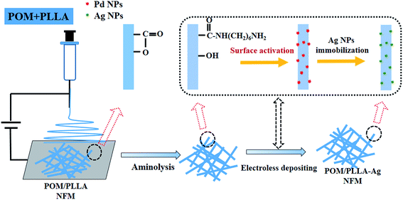
In this study, POM/PLLA NFMs were first prepared via electrospinning. The fibers were then modified by aminolysis. Finally, the Ag NP-immobilized NFMs were prepared by electroless depositing silver with dextrose as the reducing agent (Scheme 1). The formed Ag NP-immobilized NFMs were characterized by Fourier transform infrared (FTIR) spectroscopy, X-ray photoelectron spectroscope (XPS), scanning electron microscopy (SEM), transmission electron microscopy (TEM), X-ray diffraction (XRD), and thermogravimetric analysis (TGA). The catalytic efficiency and reusability of the formed Ag NP-immobilized polymer nanofibers were examined by reducing 4-nitroaniline (4-NA) into p-phenylenediamine (PPD) in the presence of NaNH4. To our knowledge, this is the first report related to the use of electrospun POM/PLLA NFMs as supporting materials to immobilize Ag NPs for catalytic applications.
2 Materials and methods
2.1 Materials
The PLLA materials (3001D) used were purchased from Nature Works Co. LLC (USA). The Mn were reported to be 89![[thin space (1/6-em)]](https://www.rsc.org/images/entities/char_2009.gif) 300 g mol−1. The content of D-lactide of the PLLA materials was 1.6%. The POM (MC90) samples were provided by Shenhua Co. Ltd, China. The Mn was 174
300 g mol−1. The content of D-lactide of the PLLA materials was 1.6%. The POM (MC90) samples were provided by Shenhua Co. Ltd, China. The Mn was 174![[thin space (1/6-em)]](https://www.rsc.org/images/entities/char_2009.gif) 300 g mol−1. Hexafluoro-2-isopropanol (HFIP) was used as the solvent for dissolving the PLLA and POM without any purification. Silver nitrate (AgNO3), palladium chloride (PdCl2), tin chloride (SnCl2), potassium hydroxide (KOH), and ammonium hydroxide (NH4OH) were purchased from the Sinoparm Chemical Regent Co. Ltd. (China) and used without further purification. All other chemicals were of analytical grade.
300 g mol−1. Hexafluoro-2-isopropanol (HFIP) was used as the solvent for dissolving the PLLA and POM without any purification. Silver nitrate (AgNO3), palladium chloride (PdCl2), tin chloride (SnCl2), potassium hydroxide (KOH), and ammonium hydroxide (NH4OH) were purchased from the Sinoparm Chemical Regent Co. Ltd. (China) and used without further purification. All other chemicals were of analytical grade.
2.2 Preparation of POM/PLLA NFMs
POM/PLLA NFMs are obtained via the technique of electrospinning according to our previous work.23 In brief, POM/PLLA solutions with proportions of 50/50 in HFIP were prepared. The resulting clear and homogeneous solutions were electrospun with a voltage of 13 kV. The polymer fibers were collected onto a sheet of aluminum foil with a tip-to-collector distance of 10 cm and a volumetric flow rate of 0.02 mL h−1. The spinning was carried out under a relative humidity of 80–85%.2.3 Preparation of aminolyzed POM/PLLA NFMs
POM/PLLA NFMs were immersed in a 1,6-hexanediamine/2-propanol solution of 60 mg mL−1 under gentle stirring for 12 h at 40 °C. When the aminolysis process completed, the membranes were rinsed with 2-propanol and water several times to wash away the unreacted 1,6-hexanediamine. The aminolyzed membranes were dried in vacuum and prepared for Ag NP deposition.2.4 Immobilization of Ag NPs onto POM/PLLA NFMs
The process of the immobilization of Ag NPs within POM/PLLA NFMs was carried out with a silver electroless deposition method.24 Briefly, a piece of aminolyzed POM/PLLA NFM (2 × 2 cm2) was immersed into a 3.0 mM SnCl2 aqueous solution for 30 min and then in a 3.0 mM PdCl2 solution for 10 min. This process would provide the Pd seeds as the active site for the following reaction of silver ions and dextrose molecules.Then the surface-activated POM/PLLA NFMs were immersed in Tollen's reagent for nucleation and growth of Ag NPs within the POM/PLLA NFMs. Tollen's reagent was prepared in two steps: firstly, a 1.0 M NH4OH aqueous solution was dropwise added into a AgNO3 (0.1 M, 30 mL) aqueous solution until the brown precipitate disappeared under constant stirring; after that, a KOH (0.8 M 15 mL) aqueous solution was added to the system, resulting in a black precipitate. Additional NH4OH was then added dropwise until the system became clear and colorless again. Finally, a dextrose (0.25 M, 3 mL) aqueous solution was added into the Tollen's reagent under constant stirring. After 3 minutes of reaction, the NFMs were thoroughly rinsed with distilled water and dried for further characterization and catalysis evaluations.
2.5 Characterization
The morphology of the electrospun POM/PLLA NFMs before and after Ag immobilization was observed using scanning electron microscopy (SEM, S-4800, Hitachi, Japan) with an accelerating voltage of 2 kV and working distance of 2–5 mm. The elemental composition of the samples was analyzed by energy dispersive spectroscopy (EDS, IE300X, Oxford, UK) attached to the SEM. To observe the distribution of Ag NPs within the fibers, the Ag immobilized POM/PLLA NFMs were embedded in epoxy resin and ultramicrotomed at −120° C to a section of thickness of about 70 nm. Transmission electron microscopy (TEM, HT7700, Hitachi, Japan) was performed at an operating voltage of 100 kV. The diameter of the nanofiber was measured using image analysis software and at least 200 randomly selected nanofibers in different SEM images were analyzed for each sample to acquire the diameter/size distribution histograms. X-ray photoelectron spectroscopy (XPS) measurements were performed on an ESCALAB 250 Xi XPS system (Thermo Electro Corporation, USA) with an Al Kα X-ray source (1486.8 eV) at a constant recording ratio of 40. Both broad and narrow (or core) scans were carried out to collect XPS spectra. TGA was carried out on a TGA Q500 (TA Instruments, USA) thermogravimetric analyzer with a heating rate of 10 °C min−1 in a nitrogen atmosphere. FTIR spectra were recorded using an ERTEX 70v FTIR spectrometer (BRUKER, USA) in the wavenumber range of 4000–500 cm−1 at ambient conditions. The apparent density and porosity of the electrospun fibrous mats before and after immobilization of the NPs were estimated using eqn (1) and (2), respectively, where the thickness of the fibrous mats was measured by a micrometer and the bulk density of the mixture was calculated according to their weight ratio in the mixture.
 | (1) |
 | (2) |
2.6 Catalytic performance evaluation
A model reaction to transform 4-NA into PPD was selected to evaluate the catalytic efficiency and reusability of the Ag-immobilized POM/PLLA NFMs. In brief, a solution mixture containing 4-NA (0.15 mM, 40 mL) and NaBH4 aqueous solution (15 mM, 40 mL) was prepared in a 100 mL three-necked flask. Then, an Ag-immobilized POM/PLLA NFMs (2 × 2 cm2) was immersed into the above solution mixture at room temperature, followed by gentle magnetic stirring. At a given time interval, 2 mL of the aqueous solution was withdrawn for the detection of the transformation efficiency using a UV-2450 spectrometer (SHIMADZU, Japan). To verify the reusability of the Ag-immobilized POM/PLLA NFMs, the mat was washed with water and blotted with filter paper before it was reused for the next cycle of catalytic reaction.To evaluate the dynamic catalytic activity, 100 mL of a solution of 4-NA (0.15 mM) was prepared. 100 mL of NaBH4 (15 mM) was added to the substrate solution under stirring. The temperature of the reactor was maintained at 25 °C during the experiment by a temperature-controlled box. The POM/PLLA/Ag NFMs were immobilized in a membrane support (13 mm diameter, Xinya, China). The catalytic disc and support unit were fed by a syringe pump (Fig. S1†) and the solution was continuously flowed through the catalytic disc at the flow rate of 0.4 mL min−1. At a given time interval, 2 mL of the aqueous solution was withdrawn for absorbance of the substrate at 381 nm (wavelength of maximum absorbance for 4-NA) with a UV-2450 spectrometer (SHIMADZU, Japan). The conversion efficiency of 4-NA transfer into PPD was calculated according to the following equation:
| Conversion efficiency = (1 − Ct/C0) × 100% | (3) |
3 Results and discussion
3.1 Formation of electrospun POM/PLLA NFMs
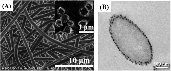
In our previous study,18 we optimized the electrospinning conditions to fabricate uniform POM/PLLA nanofibrous mats. Under the same optimum experimental parameters, nanofibers of random orientation were generated with a mean diameter of 860 ± 56 nm (Fig. 1A). With the fast evaporation of the solvent hexafluoroisopropanal (HIPF), vapor-induced phase separation between the solvent and the POM/PLLA blends occurs on the surface of the nanofibers, which leads to numerous nanopores on the surface of the as-spun nanofibers. Fig. 1B shows the TEM images of POM/PLLA nanofibers; black dots can be seen on the surface of the fibers and are considered as POM-rich regions formed during the vapor-induced phase separation, since POM is more readily stained by RuO4 than PLLA. Moreover, the as-spun nanofibers were solid and had no internal pores, which is also confirmed by Fig. 1A and B.3.2 Aminolysis of electrospun POM/PLLA NFMs
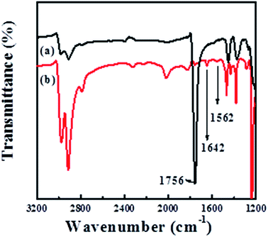
The amino group has been found to be one of the effective chelating functional groups for the adsorption of metal ions from aqueous solution and acts as an anchor for the immobilization of metal NPs. For example, Ren et al.25 prepared amino-functionalized graphene and used it as a support for the deposition of Pd NPs. Baghani26 et al. investigated the amino-functionalized magnetic nanoparticles as efficient adsorbents for metal ions. Therefore, we make use of the reaction between the ester groups (–COO–) of PLLA and the amino groups (–NH2) of 1,6-hexanediamine to introduce the –NH2 into POM/PLLA NFMs in the case that one amino group reacts with –COO– group to form a covalent bond, –CONH–, while the other amino group is unreacted; hydroxyl-terminated chains will also be yielded on the polyester surface during this process.27 Fig. 2 displays the FTIR spectra of POM/PLLA NFMs and aminolyzed POM/PLLA NFMs. In the spectrum of POM/PLLA NFMs, the peak at![[small nu, Greek, macron]](https://www.rsc.org/images/entities/i_char_e0ce.gif) = 1756 cm−1 is characteristic of the carbonyl groups of PLLA, but after aminolysis with 1,6-hexanediamine, the peak associated with the carboxyl group became weak and new peaks located at
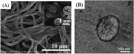
= 1756 cm−1 is characteristic of the carbonyl groups of PLLA, but after aminolysis with 1,6-hexanediamine, the peak associated with the carboxyl group became weak and new peaks located at ![[small nu, Greek, macron]](https://www.rsc.org/images/entities/i_char_e0ce.gif) = 1642 and 1562 cm−1, attributed to the –CONH– and N–H characteristic stretching bands of the amide group, respectively, are observed, indicating that –NH2 groups are successfully introduced to the POM/PLLA fibrous membranes. It is worth noting that aminolysis, in principle, is an alkaline-catalyzed degradation of PLLA macromolecules,26 as reported in our previous works.21–23 POM and PLLA formed a co-continuous structure in the internal fiber, and thus the alkaline erosion of PLLA by 1,6-hexanediamine simultaneously takes place and leads to an internal porous structure of POM/PLLA fibers. That means, the aminolysis process would provide the fibers not only with the functional groups capable of coordinating/chelating with metal ions, but also the internal nanochannels that result from the 1,6-hexanediamine alkaline erosion process. This was confirmed from both SEM and TEM images, as shown in Fig. 3A and B. The SEM image of the cross section of fiber indicates a clear image that the alkaline erosion results in an interconnected porous POM/PLLA nanofiber. The TEM image shows clear white channels with a size of several tens of nanometers and these channels were originally PLLA before the aminolysis process. Compared with the pristine nanofibers before aminolysis (Fig. 1A), the size of the aminolyzed POM/PLLA nanofibers increased in the mean fiber diameter (925 ± 37 nm), which can be ascribed to the 1,6-hexanediamine/2-propanol aminolysis process that led to the swelling of the fibers.
= 1642 and 1562 cm−1, attributed to the –CONH– and N–H characteristic stretching bands of the amide group, respectively, are observed, indicating that –NH2 groups are successfully introduced to the POM/PLLA fibrous membranes. It is worth noting that aminolysis, in principle, is an alkaline-catalyzed degradation of PLLA macromolecules,26 as reported in our previous works.21–23 POM and PLLA formed a co-continuous structure in the internal fiber, and thus the alkaline erosion of PLLA by 1,6-hexanediamine simultaneously takes place and leads to an internal porous structure of POM/PLLA fibers. That means, the aminolysis process would provide the fibers not only with the functional groups capable of coordinating/chelating with metal ions, but also the internal nanochannels that result from the 1,6-hexanediamine alkaline erosion process. This was confirmed from both SEM and TEM images, as shown in Fig. 3A and B. The SEM image of the cross section of fiber indicates a clear image that the alkaline erosion results in an interconnected porous POM/PLLA nanofiber. The TEM image shows clear white channels with a size of several tens of nanometers and these channels were originally PLLA before the aminolysis process. Compared with the pristine nanofibers before aminolysis (Fig. 1A), the size of the aminolyzed POM/PLLA nanofibers increased in the mean fiber diameter (925 ± 37 nm), which can be ascribed to the 1,6-hexanediamine/2-propanol aminolysis process that led to the swelling of the fibers.
Aminolysis of POM/PLLA NFMs was further confirmed by X-ray photoelectron spectroscopy (XPS) measurements. Fig. 4A shows the XPS survey profiles of the POM/PLLA NFMs and aminolyzed POM/PLLA NFM samples. For POM/PLLA NFMs, only C 1s and O 1s peaks are observed, whereas a new peak for N 1s appears in the XPS spectrum of the aminolyzed POM/PLLA nanofibers. In addition, the N 1s XPS spectrum of the aminolyzed POM/PLLA NFMs (Fig. 4B) displays a peak at binding energies of approximately 399.6 eV, which can be assigned to amide atoms.27 Therefore, the FTIR spectra together with the XPS spectra demonstrate that POM/PLLA NFMs have been successfully modified by 1,6-hexanediamine through the aminolysis reaction.
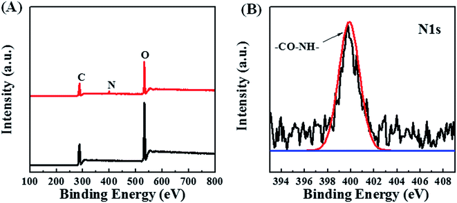 | ||
| Fig. 4 XPS survey spectra of aminolyzed POM/PLLA NFMs (A), and N 1s spectra of aminolyzed POM/PLLA NFMs (B). | ||
3.3 Ag NP-immobilized POM/PLLA NFMs
A typical SnCl2/PdCl2 method was applied to introduce palladium seeds on the NFM surface to get the surface-activated POM/PLLA NFMs. The Ag NPs were then grown on the surface of nanofibers by electroless plating or deposition to get Ag NP-immobilized NFMs (POM/PLLA-Ag NFMs). Fig. 5A shows a typical SEM image of POM/PLLA-Ag NFMs. It is clear that the composite NFMs still retain a uniform fibrous structure with a porous surface, similar to the nanofibers without Ag NPs (Fig. 3A). Many nanoscale particles could be observed on the surface of the nanofibers; these bright particles were Ag NPs because silver can scatter more electrons than polymer nanofibers. From the SEM images, it was concluded that the Ag NPs were randomly distributed on the nanofibers. Since the major advantage of electrospun nanofibers is their high porosity, which allows sufficient contact with the reactant molecules for efficient reactions, it is critical to check if the immobilization of the Ag NPs affects the porosity of the POM/PLLA nanofibers. Knowing the bulk densities of POM and PLLA polymers, along with the calculated apparent density of the nanofibers, we were able to estimate the porosities of POM/PLLA NFMs before and after Ag immobilization. The porosity of the pristine NP-free aminolyzed POM/PLLA NFMs is 53.4%, while after Ag NP loading, the porosities of the Ag NP-containing nanofibrous mats slightly decreased to 44.8%, but still higher than the porosity of pristine nanofibers (31.1%) before aminolysis. This porous structure would effectively facilitate liquid-fuel diffusion to the surface of the outer and inner catalysts and would thus maximize the reagent molecules available at the catalysts.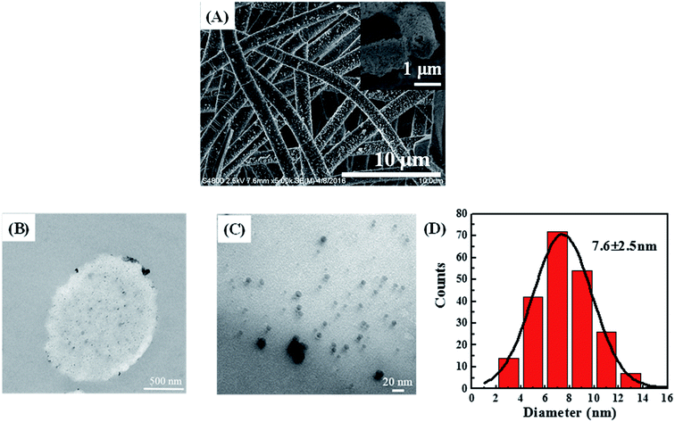 | ||
| Fig. 5 SEM images (A) of POM/PLLA-Ag NFMs (the inset is a cross-sectional SEM image). Cross-sectional TEM images (B) and (C) of POM/PLLA-Ag NFMs. Size distributions of the immobilized Ag NPs (D). | ||
The distribution of Ag NPs within the POM/PLLA NFMs was characterized by cross-sectional TEM imaging of the hybrid NFMs (Fig. 5B and C). Round-shaped patterns of the Ag NPs are clearly observed, indicating that the Ag NPs were successfully immobilized in the cross section of POM/PLLA NFMs. The mean diameter of the Ag NPs was estimated to be 7.6 ± 2.5 nm by measuring the diameter of 200 randomly selected particles (Fig. 5D).
To further confirm the presence of Ag NPs, X-ray diffraction (XRD) was carried out on POM/PLLA-Ag NFMs (Fig. 6A). Diffraction peaks centered at 2θ angles of 38.2°, 44.5°, 64.5° and 77.3° were observed, and could be assigned to (111), (200), (220) and (311) crystallographic planes of the cubic crystal structure of silver metal, respectively. The above results are consistent with the ASTM standard (JCPDS Card no. 04-0783) and confirmed that the Ag nanoparticles immobilized in the membranes exist in the zero valent state. The average size of the Ag nanoparticles was 7.2 nm, calculated from the XRD data according to the line width of the maximum intensity reflection peak Ag (111) by using the Scherrer equation [eqn (4)], in which D is the average particle size (in nm), κ is the Scherrer constant (0.89), λ is the X-ray wavelength (λ = 0.15406 nm), β is the width of the diffraction peak at half height (in radians), and θ is the Bragg diffraction angle.
 | (4) |
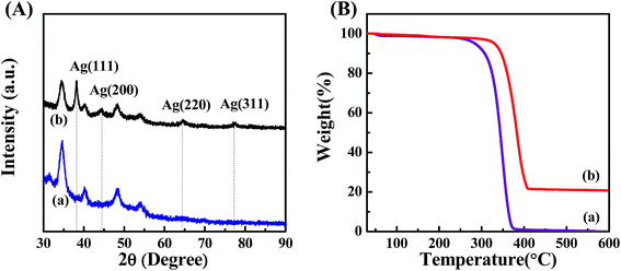 | ||
| Fig. 6 (A) XRD pattern of aminolyzed POM/PLLA NFMs before (a) and after (b) the Ag deposition. (B) TGA curves of aminolyzed POM/PLLA NFMs before (a) and after (b) the Ag deposition. | ||
TGA was used to characterize the loading capacity of Ag NPs, in the POM/PLLA-Ag NFMs (Fig. 6B). At a temperature above 600 °C, the polymer component of POM/PLLA NFMs burned out, and silver oxide residues were left. By comparison of the Ag NP-immobilized NFMs with the Ag-free membranes (Fig. 6B, curves a and b), the loading capacity of Ag NPs within the NFMs was estimated to be 20.7%.
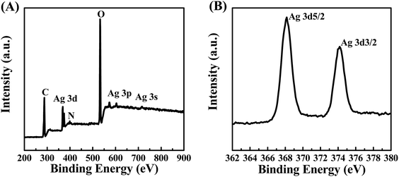
XPS was employed to further analyze the composition and surface states of the POM/PLLA NFMs immobilized with Ag NPs. The binding energies of Ag 3d at about 370 eV, Ag 3p at 571.3 eV and 601.7 eV, and Ag 3s at 715.1 eV are distinct in Fig. 7A and demonstrate the presence of the silver element.28 The Ag 3d core-level spectrum shown in Fig. 7B can be deduced from the two peak components at BEs of 368.1 eV and 374.1 eV for Ag 3d5/2 and Ag 3d3/2, respectively. Both peaks are attributed to the Ag0 species, thus confirming the presence of Ag, in good accordance with XRD results.
3.4 Catalytic activity of POM/PLLA-Ag NFMs
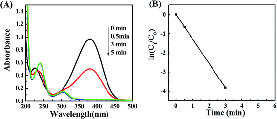
To investigate the catalytic activity of POM/PLLA-Ag NP NFMs, the reduction of 4-NA with NaBH4 in aqueous solutions was tested. The produced PPD as a reduction product of 4-NA is considered a useful and attractive intermediate in the preparation of polymers, hair dyes, and rubber products.29,30 The reduction was monitored by UV/vis measurements during a certain time interval. A blank experiment was carried out for the reduction of 4-NA with NaBH4 in the absence of POM/PLLA-Ag NFMs. There is almost no change of the characteristic absorbance of 4-NA at 378 nm even for a large excess of NaBH4. (Fig. S2†). However, when the reaction was performed in the presence of POM/PLLA-Ag NFMs the absorbance peak at 378 nm showed a progressive decrease, a shifting of the absorbance peak at 223 nm, and the appearance of a new absorption peak at 303 nm (Fig. 8A), due to the formation of PPD.31,32 This result indicates that the POM/PLLA-Ag NP NFMs accelerated the reduction of 4-NA into PPD in the presence of NaBH4. Notably, a complete reduction of 4-NA using our prepared POM/PLLA-Ag NFMs occurred within 3 minutes of starting the reaction. Catalytic activities are mainly determined by two key parameters, such as the availability of active surface area and the catalyst active sites on the surface for the electron transfer, which remove the kinetic barrier.33 The superior catalytic properties of our POM/PLLA-Ag NFMs could be attributed to the high surface activity of the silver NPs and the high surface area of the NFMs.The reduction rates of this reaction can be considered to be independent of the concentration of NaBH4 since this reagent was used in large excess with respect to 4-NA. Therefore, this chemical reduction follows first-order kinetics. Fig. 8B shows the plot of ln(Ct/C0) versus reaction time, where Ct is the concentration of 4-NA at reaction time t and C0 is the initial concentration of 4-NA. The results indicate that ln(Ct/C0) decreases linearly with reaction time; we estimated that the first-order rate constant (k) of the reaction was 21.25 × 10⁻³ s−1. We compared the catalytic capacities of POM/PLLA-Ag NFMs in this work with the data in other literature (Table 1). PEGPU-Au34 and P(NiPA-co-AAc) microgels35 have a rate constant k of 1.4 × 10⁻³ s−1 and 16.60 × 10⁻³ s−1, respectively. Our POM/PLLA-Ag NFMs exhibit a significantly higher catalytic activity for the reduction reactions than the Ag-based catalysts mentioned above. What's more, the rate constant k of POM/PLLA-Ag NFMs is also higher than those of the reported silver-nanospheres (Ag-NSs) even for a similar size of 7 nm.36 The excellent catalytic activity of POM/PLLA-Ag NFMs could be attributed to the highly dispersed small-sized Ag NPs with an easy accessibility of the active sites benefited by the porous structure of fibers. Therefore, 4-NA and BH4− were easily absorbed on the surface of Ag NPs of POM/PLLA-Ag NFMs, where the Ag-NPs trigger the reduction of the 4-NA solution by relaying electrons from the BH4− donor to Ag NPs, and then conveying the electrons to the acceptor 4-NA molecules, resulting in a rapid occurrence and completion of the reduction reaction.37,38
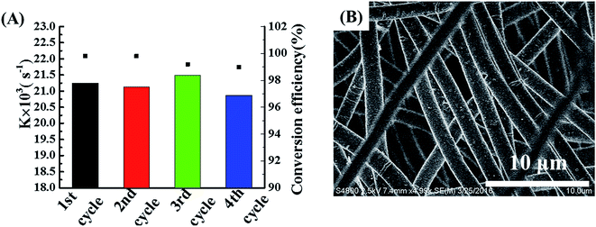
The reusability and recyclability are crucial issues for a catalyst to be used for practical applications. The formed freestanding POM/PLLA-Ag NFMs with good mechanical durability are essential for them to be recycled for multiple catalytic uses. After each reaction cycle, the membrane was washed with water and blotted by a filter paper before it was reused for the next cycle of catalytic reaction. The catalytic performances of the POM/PLLA-Ag NFMs used 4 different times were compared by plotting the first-order rate constant and 4-NA conversion as a function of reaction time (Fig. 9A). It can be seen that more than 99% 4-NA is able to be transformed to PPD after 4 reaction cycles and each cycle keeps similar k values, confirming the excellent reusability of the POM/PLLA-Ag NFMs. The morphology of the POM/PLLA-Ag NFMs were checked by SEM (Fig. 9B) and the result shows that the porous nanofibrous structure of the POM/PLLA-Ag NFMs are very stable, even after undergoing multiple catalytic reaction cycles.
Furthermore, the dynamic catalytic activity was evaluated. The mixture of 4-NA and the NaBH4 aqueous solution was pumped to the catalytic disc immobilized at a constant flow rate (0.4 mL min−1) without solution recycling (single-pass mode). The video file in the ESI† demonstrates the continuous reduction of 4-NA into PPD in single-pass mode (Video S1†). As shown in Fig. 10, the continuous conversion efficiency keeps above 90% even after 4 hours of running time. This means that the catalytic POM/PLLA-Ag NFMs are able to reduce 96 mL of 4-NA at a concentration 0.75 mM (i.e. 103 mg 4-NA) before the conversion rate is lower than 90%.
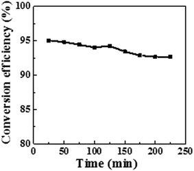 | ||
| Fig. 10 Conversion efficiency as a function of reaction time in the presence of the POM/PLLA-Ag NFMs as the catalysts for continuous reduction. | ||
4 Conclusions
In summary, we have developed a facile approach to prepare porous POM/PLLA-Ag NFMs. The immobilization of the Ag NPs with a mean diameter of 7.6 ± 2.5 nm within the POM/PLLA nanofibers does not impact the porous fibrous structure of the membranes. The catalytic reaction to transform 4-NA into PPD demonstrates that the Ag NPs immobilized within the NFMs are able to catalyze the 4-NA reducing reaction with an efficiency approaching 99.7% within 5 min at 25 °C. Furthermore, the POM/PLLA-Ag NFMs can be easily handled and reused at least 4 times with an approximately similar catalytic performance and the continuous conversion rate of 4-NA keeps above 90% even after 4 hours of running time. These findings provide new thoughts or avenues for fabricating highly efficient nanofiber-based cost-effective catalysts for various catalytic applications.Conflict of interest
The authors declare no competing financial interest.Acknowledgements
The authors acknowledge financial support from the Natural Science Foundation of China (Grant No. 51203134, 21374027, 51173036) and Zhejiang Provincial Natural Science Foundation of China (Grant No. LY15E030014).References
- S. S. Shankar, L. Rizzello, R. Cingolani, R. Rinaldi and P. P. Pompa, ACS Nano, 2009, 3, 893–900 CrossRef CAS PubMed.
- Z. L. Zhang and W. Y. Zhu, J. Alloys Compd., 2015, 649, 687–693 CrossRef CAS.
- X. Yang, S. S. Fu, G. J. Ren, F. Chai and F. Y. Qu, Eur. J. Inorg. Chem., 2015, 2015, 5411–5418 CrossRef CAS.
- Y. Tian, Y. Liu, W. P. Wang, X. Zhang and W. Peng, J. Nanopart. Res., 2015, 17, 1–9 CrossRef CAS.
- P. K. Sonkar and V. Ganesan, J. Solid State Electrochem., 2015, 19, 2107–2115 CrossRef CAS.
- D. Tomacheski, M. Pittol, V. F. Ribeiro and R. M. Santana, J. Appl. Polym. Sci., 2016, 133, 43956–43961 CrossRef.
- H. Cai, K. Li, M. Shen, S. Wen, Y. Luo and C. Peng, J. Mater. Chem., 2012, 22, 15110–15120 RSC.
- J. Chen, Y. Sun, Q. Chen, L. Wang, S. Wang and Y. Tang, Nanoscale, 2016, 8, 13568–13573 RSC.
- R. Guo, Y. Yao, G. Cheng, S. H. Wang, Y. Li and M. Shen, RSC Adv., 2012, 2, 99–102 RSC.
- H. Liu, Y. Xu, S. Wen, J. Zhu, L. Zheng and M. Shen, Polym. Chem., 2013, 4, 1788–1795 RSC.
- A. S. Momeni, J. Hazard. Mater., 2012, 201–202, 125–131 Search PubMed.
- V. Gunasekar and V. Ponnusami, J. Sol-Gel Sci. Technol., 2015, 74, 84–93 CrossRef CAS.
- M. H. Rashid and T. K. Mandal, J. Phys. Chem. C, 2007, 111, 16750–16760 CAS.
- Z. D. Zhou, X. W. Peng, L. X. Zhong, L. Wu, X. F. Cao and R. C. Sun, Carbohydr. Polym., 2016, 136, 322–328 CrossRef CAS PubMed.
- J. Y. Cheon, Y. O. Kang and W. H. Park, Fibers Polym., 2015, 16, 840–849 CrossRef CAS.
- H. R. Pant and D. R. Pandeya, J. Hazard. Mater., 2011, 189, 465–471 CrossRef CAS PubMed.
- W. J. Jin, H. J. Jeon, J. H. Kim and J. H. Youk, Synth. Met., 2007, 157, 454–459 CrossRef CAS.
- T. Cohen-Kami, K. J. Jeong and J. H. Tsui, Nano Lett., 2012, 12(10), 5403–5406 CrossRef PubMed.
- B. Carlber, L. L. Ye and J. Liu, Small, 2011, 7(21), 3057–3066 CrossRef PubMed.
- J. Wang, H. B. Yao and D. He, ACS Appl. Mater. Interfaces, 2012, 4(4), 1963–1971 CAS.
- J. S. Qiu, C. Y. Xing, X. J. Cao, H. T. Wang, L. Wang, L. P. Zhao and Y. J. Li, Macromolecules, 2013, 46, 5806–5814 CrossRef CAS.
- L. J. Ye, J. S. Qiu, T. Wu, X. C. Shi and Y. J. Li, RSC Adv., 2014, 4, 43351–43356 RSC.
- J. P. Guan, L. J. Ye and Y. J. Li, RSC Adv., 2016, 6, 33781–33788 RSC.
- J. J. Feng, M. Sun, J. B. Li, X. Liu and S. S. Jiang, Anal. Chim. Acta, 2011, 701, 174–180 CrossRef CAS PubMed.
- F. F. Ren, K. Zhang, D. Bin, B. B. Yang, H. W. Wang, P. Yang, Z. H. Fei and Y. K. Du, ChemCatChem, 2015, 618, 61–69 Search PubMed.
- A. N. Baghani, A. H. Mahvi, M. Gholami, N. Rastkari and M. Delihoon, J. Environ. Health Sci. Eng., 2016, 14, 11–22 CrossRef PubMed.
- J. F. Bunnett and G. T. Davis, J. Am. Chem. Soc., 1960, 82, 665–674 CrossRef CAS.
- T. Diemant, K. M. Schüttler and R. J. Behm, ChemPhysChem, 2015, 16, 2903–2907 CrossRef.
- H. S. Lee and Y. W. Lin, Ann. Occup. Hyg., 2009, 53, 289–296 CrossRef CAS PubMed.
- Y. Ikarashi and M. A. Kaniwa, J. Health Sci., 2000, 46, 467–473 CrossRef CAS.
- X. Huang, X. P. Liao and B. Shi, Green Chem., 2011, 13, 2801–2805 RSC.
- Q. Zhou, G. Z. Qian, Y. Li, G. Zhao, Y. W. Chao and J. W. Zheng, Thin Solid Films, 2008, 516, 953–956 CrossRef CAS.
- Y. Yang, Y. Ren, C. J. Sun and S. J. Hao, Green Chem., 2014, 16, 2273–2280 RSC.
- V. Ramtenkia, V. D. Anumonb, M. V. Badigerb and B. L. Prasada, Colloids Surf., A, 2012, 414, 296–301 CrossRef.
- Z. H. Farooqi, A. ljaz, R. Begum, K. Naseem, M. Usman, M. Ajmal and U. Saeed, Polym. Compos., 2016, 201–202, 125–129 Search PubMed.
- B. Vellaichamy and P. Periakaruppan, RSC Adv., 2015, 5, 105917–105924 RSC.
- J. Li, C. Y. Liu and Y. Liu, J. Mater. Chem., 2012, 22, 8426–8430 RSC.
- S. Kundu and M. Jayachandran, RSC Adv., 2013, 3, 16486–16498 RSC.
Footnote |
| † Electronic supplementary information (ESI) available: The experimental set-up for the investigation of continuous catalytic hydrogenation of 4-NA using POM/PLLA-Ag NFMs (Fig. S1); UV-visible spectra for the successive chemical reduction of 4-NA with NaBH4 without POM/PLLA-Ag NFMs (Fig. S2); video of the continuous reduction of 4-NA into PPD in single-pass mode (Video S1). See DOI: 10.1039/c6ra28167b |
| This journal is © The Royal Society of Chemistry 2017 |

