 Open Access Article
Creative Commons Attribution 3.0 Unported Licence
Triboelectric nanogenerator based on 317L stainless steel and ethyl cellulose for biomedical applications
Mengmeng Wanga,
Wei Li*ab,
Chen Youab,
Qi Wanga,
Xianshun Zenga and
Minfang Chen *ab
*ab
aSchool of Materials Science and Engineering, Tianjin University of Technology, Tianjin 300384, China. E-mail: mfchentj@126.com; weilitjut@126.com
bKey Laboratory of Display Materials and Photoelectric Device (Ministry of Education), Tianjin University of Technology, Tianjin 300384, China
First published on 20th January 2017
Abstract
For the application of implanted medical devices, a sustainable energy supply is crucial to avoid the traditional battery that is of high risk and can lead to the need for second surgery. The development of triboelectric nanogenerators (TENGs) provides a new approach to supply green energy. Here, we demonstrate a biomedical TENG based on tribo-electrification and electrostatic induction between biocompatible medical 317L stainless steel (317L SS) plate and ethyl cellulose (EC) film. The surfaces of both 317L SS and EC were designed using lithography technology and inductively coupled plasma (ICP) etching, respectively. The mechanism and power output of the TENG as well as the effective sliding friction on the tribo-interface were investigated. It was found that with an increase of designed pattern density on the surface of 317L SS by using a designed lithography mask and EC by increasing the ICP etching power, the power output of the TENG was greatly increased. At the optimum condition, the open-circuit voltage and short-circuit current of TENG can reach 245 V and 50 μA. The performance of the TENG in biological medicine was also studied. On increasing the time of the TENG immersed in simulated body fluid for a month, its performance was not changed obviously. These results reveal that our biocompatible TENG has great potential applications in biomedical science.
1. Introduction
Mechanical energy harvesting using nanogenerators has attracted considerable research attention owing to the technological potential to realize a self-powered system, which is a cost-effective method to get a sustainable power source. Several relevant technologies have been developed based on piezoelectric,1–6 thermoelectric,7–9 and triboelectric effects (contact electrification).10–18 In particular, the triboelectric nanogenerator (TENG) using triboelectric effects has attracted great attention. Two processes can improve the output power of a TENG. One is generating more triboelectric charges. To maximize the generation of triboelectric charges, the modification of surface morphology and the choice of materials with different ability to attract electrons are required. The other process is a periodic separation of the oppositely charged surfaces with a change of the induced potential between the electrodes, which can be improved by the choice of materials. For the application of implanted medical devices, sustainable power sources are crucial to avoid the traditional battery's high cost and high risk of second surgery.Materials with good biocompatibility and high elasticity can be used in the preparation of TENGs.19 Mg-PLLA TENG and Mg-Kapton TENG were developed in our previous studies.20 Mg is an excellent biomaterial, which can be implanted in the body. However, the poor plasticity and back stretch of Mg limits it as a metal plate of a TENG. Al has excellent plasticity and good stretch, but it is harmful to the body. While stainless steel (iron is the main component) and titanium alloy are widely used as medical metal materials, crystalline structure determines that the elasticity and machinability of iron are better than those of titanium. In addition, studies have shown that when medical stainless steel is implanted in the body for a long time, local or systemic toxicity reaction cannot occur and the released Fe2+ ions are beneficial to the body,21 such as in the growth of new tissue and promoting wound healing.22 Obviously, medical stainless steel as an ideal biologically compatible frictional material can be used as a TENG's electronic plate material. Medical 317L stainless steel (317L SS) has the advantages of biocompatibility and good plasticity as well as good stretch. Previous studies have indicated that the materials we choose are far apart in the sequence table of friction, being beneficial to improve the electrical output signal of TENGs.23 Ethyl cellulose (EC) is a biocompatible material, far apart from the location of Fe (317L SS), and has high positive charge ability in the process of friction,23 which can be used as a plate of a generator. The simply produced silver paste electrode with relatively high conductivity has advantages in the biomedical field with the inhibition of some pathogenic microorganisms.
To offer a simple and cost-effective approach for driving small devices used in the biomedical field, we develop a simple, cost-effective TENG, mainly consisting of two biocompatible materials: EC and medical 317L SS. The surfaces of both 317L SS and EC were designed using lithography technology and inductively coupled plasma (ICP) etching. The mechanism, surface density, and power output of the TENG were investigated. It was found that with an increase of the surface density for 317L SS and the ICP etching power for EC, the power output of the TENG was greatly increased. At the optimum condition, 18 paralleled commercial LEDs can be driven by our TENG. Through the roughness tests of the tribo-interface, it was also found that the power output of the TENG was increased with an increase of surface roughness as well as an increase of the appropriate surface density. The implantable electronic devices composed of biomedical materials are expected to achieve their independent, no maintenance and sustainable work in the application of clinical medicine.
2. Experimental
2.1. Fabrication of the films
317L SS film: a flexible 317L SS film (50 μm in thickness, 20 mm wide by 30 mm long) was used as the top plate of the TENG, whose structural patterns were designed using lithography technology (the lithography technology machine used was a SUSS MA6, Germany). Three different pattern densities were designed on the surfaces of 317L SS film.EC film: EC powder with a weight of 5 g was dissolved in a Petri dish of 100 mm in diameter into a dichloromethane![[thin space (1/6-em)]](https://www.rsc.org/images/entities/char_2009.gif) :
:![[thin space (1/6-em)]](https://www.rsc.org/images/entities/char_2009.gif) ethanol (3
ethanol (3![[thin space (1/6-em)]](https://www.rsc.org/images/entities/char_2009.gif) :
:![[thin space (1/6-em)]](https://www.rsc.org/images/entities/char_2009.gif) 1) mixture by using magnetic stirring at 600 rpm for 30 min. Then, the EC film was made from the solution using an automatic film coater until dichloromethane and ethanol volatilized completely. Finally, the thickness of the obtained EC film was about 37 μm, and 20 mm wide by 30 mm long. The surface of EC was designed using ICP etching (the ICP etching machine used was an ME-6A, China) with different etching powers. When the power is 275 W, the largest density of etching patterns is obtained.
1) mixture by using magnetic stirring at 600 rpm for 30 min. Then, the EC film was made from the solution using an automatic film coater until dichloromethane and ethanol volatilized completely. Finally, the thickness of the obtained EC film was about 37 μm, and 20 mm wide by 30 mm long. The surface of EC was designed using ICP etching (the ICP etching machine used was an ME-6A, China) with different etching powers. When the power is 275 W, the largest density of etching patterns is obtained.
2.2. Fabrication of the triboelectric nanogenerator
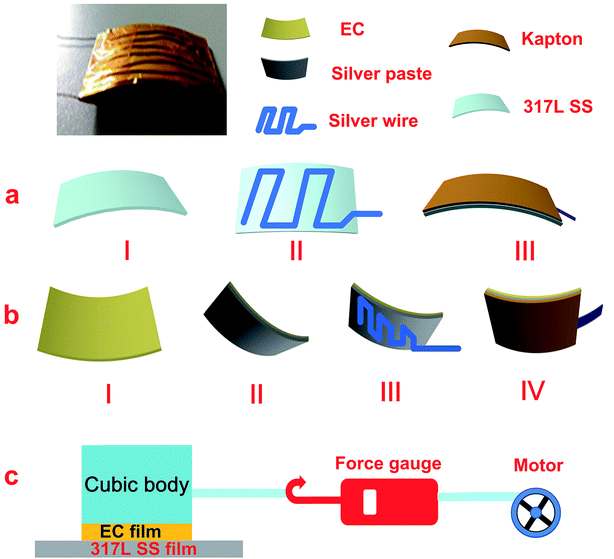
The structural design and fabrication process of an arch-shaped biocompatible polymer-based TENG are shown in Fig. 1. The TENG is made of a 317L SS-based film as the top plate and an EC-based film as the bottom plate by their face-to-face attachment. The top part starts from a piece of 317L SS film with one surface being designed using lithography technology to increase the surface micron roughness (Fig. 1a(I)); then, a silver line which is good for body was used as the guide line (Fig. 1a(II)). The folding silver line was glued on a Kapton tape and then they were coated on the electrode (Fig. 1a(III)). The bottom part starts from a piece of EC film with one surface being fabricated via ICP etching to increase the roughness to about one hundred nanometers (Fig. 1b(I)) and the other surface being coated with a layer of silver paste film. To increase the Ag film conductivity, silver paste with the EC substrate was heated at 120 °C and −0.1 MPa for 30 min in vacuum. Then the arch-shaped substrate was formed toward the Ag side owing to the different thermal expansion coefficients (Fig. 1b(II)). Finally, to increase the contact area of the electrode with the external Ag line (Fig. 1b(III)), the folding Ag line was glued on the Kapton tape and then they were coated on the electrode (Fig. 1b(IV)). Our design of TENG (size: 2 cm × 3 cm) uses biocompatible materials with fewer process steps, which is beneficial for large-scale production in the biomedical field.2.3. Electrical measurement of triboelectric nanogenerator
A vibration system, including a linear motor and tension dynamometer, was assembled to apply a friction dynamometer. The open-circuit voltage and short-circuit current of this TENG were measured using Stanford Research Systems equipment, including TEKRONIX TBS1000 and SR570 low noise current amplifiers.2.4. The test of tribo-interface film's sliding friction
The experimental procedure was as follows: the EC film (20 mm wide by 30 mm long) was affixed to the bottom surface of a cubic block (weight is 40 g, side length is 2 cm). Then the EC film with the cubic block was contacted with the 317L SS film. One side of the cubic block was connected with a force gauge whose other side was connected with a motor (10 rpm), as shown in Fig. 1c. The measured value of the force gauge is the sliding friction force between the two films. The dynamic friction factor was calculated by the formula: μ = f/N (f is tensile force, N is gravity, μ is dynamic friction factor).3. Results and discussion
3.1. Working principle of the TENG
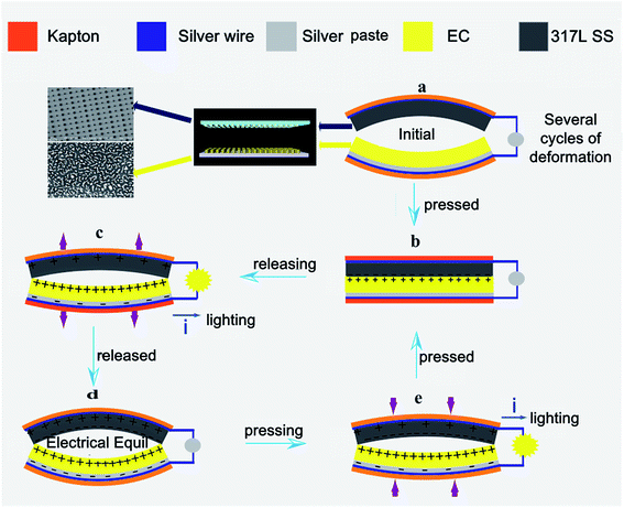
The operating principle of the TENG is based on tribo-electrification and electrostatic induction,24,25 which are related to the generation of large numbers of positive and negative charges during rubbing between two films.26–30 Fig. 2 shows the process of the electronic generation and transformation when EC and 317L SS films come into contact at the interface. At the original state before deformation takes place, there is no charge generated on the triboelectric films, thus no electric potential (Fig. 2a). As external forces are applied, the two triboelectric films are brought into contact with relative sliding and generating equal and opposite triboelectric charges. Electrons transfer from EC to 317L SS due to the stronger ability of 317L SS to gain electrons, leaving positive charges on the surface of EC (Fig. 2b). Owing to the nature of the insulator, the triboelectric charges will be preserved on the surfaces.27,28 Once the nanogenerator starts to be released, both films have a tendency to recover their original shapes due to the restoring force from deformation. Then, the separation between films brings about an electric potential difference which drives electrons to flow from the top electrode (317L SS) to the bottom electrode (EC) and produce an instantaneous current (Fig. 2c). During the releasing process, the electric potential difference keeps increasing until reaching a maximum value when the films fully revert to the original state, indicated in Fig. 2d. Once the nanogenerator is pressed again, the electric potential difference starts decreasing with the reduction of the interlayer distance, which drives electrons to flow in the opposite direction. As a consequence, this process achieves an instantaneous reversed current (Fig. 2e). When the two films are in full contact again, all of the inducted charges are neutralized and the nanogenerator will go back to the equilibrium state (Fig. 2b). This is a complete cycle of power generation.3.2. The effect of pattern density of EC on the performance of the TENG's output
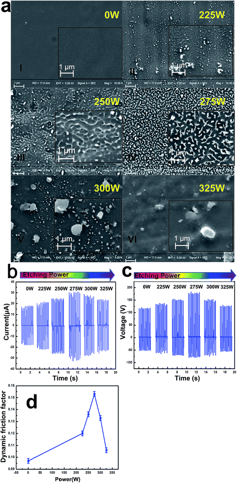
Generally, the electric output performance and efficiency can be improved by two physical processes: increasing the immobile charge generation and improving the free electron transfer. The materials of the frictional layers of the TENG are critical to obtain immobile charges. Considering the material biocompatibility, biological material 317L SS and EC as frictional layers were chosen. The surfaces of both 317L SS and EC were designed using lithography technology and ICP etching, respectively. Fig. 3 shows the electric output performance of EC-317L SS TENG with different EC etching patterns (317L SS film density is 1 × 104 mm−2). The different etching patterns of EC were obtained under different etching powers. Here, six groups of data were chosen. As shown in Fig. 3a, with an increase of etching power from 0 to 275 W, trillions of micro-patterns were produced and pattern density increased gradually. However, when the etching power continued increasing, fewer micro-patterns were observed and the pattern density decreased. This is because the EC film was limited by its thermal stability and the surface structure of EC film was destroyed by the higher etching power. Thus, an etching power of 275 W is the optimum. The EC pattern density was thus obtained. The corresponding short-circuit current and open-circuit voltage of TENGs with different pattern densities are shown in Fig. 3b and c. With the increase of etching power from 0 to 275 W, the short-circuit current and open-circuit voltage increased from 16 to 31.5 μA and 120 to 176 V, respectively, while with the increase of etching power from 275 to 325 W, both of them decreased. The short-circuit current and open-circuit voltage of the TENG could reach 31.5 μA and 176 V when the etching power was 275 W. This result was consistent with the largest pattern density at 275 W.Generally, the greater the friction effect between the rubbing contacts at the interface, the higher the output performance of the TENG. To further prove the friction effect between the two films' tribo-interface with an increase of etching power, an investigation of the tribo-interface film dynamic friction factor was performed.
Fig. 3d shows the frictional factor with different etching powers. As shown in Fig. 3d, the dynamic friction factor between the tribo-interface increased from 0.097 to 0.154 with an increase of the etching power from 0 to 275 W and then decreased to 0.15 with a continuing increase of the power to 325 W. This was because after ICP etching, the surface of the EC film has trillions of toughness micro-slender cylinders. The cylinders can produce more restoring force when subjected to external force. The greater the restoring force, the greater the force of friction. However, when the power was higher than the thermal stability of EC, the restoring force decreased with the damaged film and fewer micro-cylinders. Thus, this can be an explanation of the higher power output of the TENG with a higher surface density.20,31,32 Based on the above analysis, increasing the micro-patterns on the film surface can improve the output performance of the TENG. The EC film shows the best etching effect when the power is 275 W. The etched EC film with more micro-patterns has more effective friction with the 317L SS film, and the dynamic friction factor of the EC film was increased. Thus, more electronics generated on the surfaces of EC resulting in enhancing the output performance of TENG.
3.3. The effect of lithography technology pattern density of 317L SS on the performance of the TENG's output
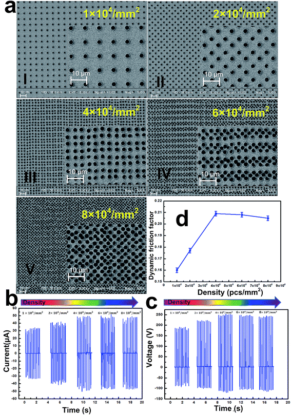
To improve the output power of the TENG, micro-patterns on surfaces of 317L SS were made using lithography. As shown in Fig. 4a, five different pattern densities of stainless steel, 1 × 104 mm−2, 2 × 104 mm−2, 4 × 104 mm−2, 6 × 104 mm−2 and 8 × 104 mm−2, were made. The designed lithography pattern was circular, and the diameter was 3 μm. The short-circuit current and open-circuit voltage are shown in Fig. 4b and c. With an increase of pattern density, both of them increased gradually in the early stage. When the density was 4 × 104 mm−2, the output performance of the TENG was a maximum: the short-current from 35 μA reached 50 μA, and the open-voltage from 188 V grew to 245 V. However, when the pattern density increased to 8 × 104 mm−2, the changes of both values remained stable. This result might be because when the pattern size is very small, sliding friction is not always proportional to lithography pattern density. When the pattern density was over a certain value, the effective contact at the interface decreased as a result of the 317L SS film and EC film possessing different size patterns. Although the lithography area increased, the area of effective friction did not increase. Shown in Fig. 4d is the sliding friction of 317L SS film with different lithography pattern densities. With an increase of pattern density, the effect of dynamic friction factor increases gradually in the early stage. When the density is 4 × 104 mm−2, the effect of dynamic friction factor reached the maximum value, which was consistent with above analysis of the effect of pattern density on the output power of the TENG.These results indicate that the surface micro-patterns increase the sliding friction force of the film. Thus, it can be an explanation of the higher power output of the TENG with a higher surface density.
3.4. The application of 317L SS–EC TENG
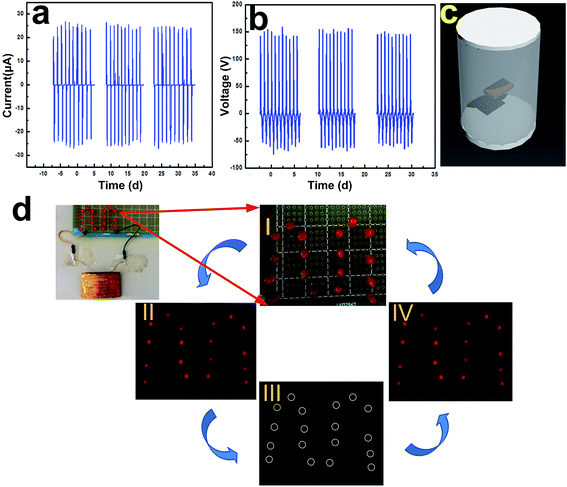
To study the biomedical performance of the 317L SS–EC TENG, tests of the TENG immersed into simulated body fluids for different times were performed. The TENG's short-circuit current and open-circuit voltage are shown in Fig. 5a and b, respectively. With increasing the storage time from 0 day to 15 days until 30 days, the short-circuit current and the open-circuit voltage were 25 μA, 25 μA and 24.5 μA, and 152 V, 152 V and 150 V, respectively, which were not obviously changed. Although these values were lower compared with the maximum output values (245 V and 50 μA) owing to the whole TENG being directly immersed in the simulated body fluid without any protecting layer, these results still confirmed that the TENG has a good stability after immersion in the simulated body fluid and can be used to drive many micro-medical devices.To further explain the working principle of the TENG, it was used as a direct power source to power LEDs without any rectifier unit or energy storage unit. Fig. 5d(I) and (III) shows two processes (corresponding to Fig. 2a and d, respectively): two triboelectric films before contact, and with contact for a few seconds during one cycle. Due to the fact that charges could not be generated and transform completely during these two processes, the LEDs could not be powered. Fig. 5d(II) and (IV) shows snapshots of LEDs driven by the instantaneous output of the device. In these two processes, eighteen LEDs were lit instantaneously owing to charge flow. These results reveal that the instantaneous output current generated by our TENG could be used to power those biomedical electronic devices which work with small current. The real-time current signals are observed such that the current peak of the pressing process has a bigger magnitude but lasts a shorter time than for the releasing process. This should be caused by the fact that compared with the resilience of the arch-shaped 317L SS–EC film that leads to release, the external force applied to the pressing process instantaneously corresponds to a shorter process and thus a higher but narrower current signal. This illustration clearly demonstrates that this TENG has the ability to be a direct power source and then continuously drive small electronic devices.
4. Conclusions
We demonstrated a biomedical TENG based on tribo-electrification and electrostatic induction between biocompatible 317L SS and EC films. The surface pattern densities of both 317L SS and EC were designed using lithography technology and ICP etching, respectively. With an increase of the surface pattern density, the power output of the TENG was greatly increased, which was consistent with the increase of effective sliding friction. At the optimum conditions, an obtained density of 4 × 104 mm−2 of 317L SS and etching power of 275 W for EC, the power output of the TENG reached a maximum, with the short-circuit current and the open-circuit voltage of the TENG reaching 50 μA and 245 V, respectively, which can drive about 18 paralleled commercial LEDs. The performance of the TENG in biological medicine was also studied. After the TENG was immersed in simulated body fluid for a month, both short-circuit current and open-circuit voltage were about 24.5 μA and 150 V, which were not changed obviously. Thus, our biocompatible TENG has great potential applications in biomedical fields.Acknowledgements
The authors acknowledge the financial support for this work from the National Nature Science Foundation of China (no. 51501129, 51371126), Tianjin “131” Innovative Talents (the third level in 2015), Science and Technology Supporting Program in Tianjin (no. 14ZCZDGX00007), Tianjin Key Subject for Materials Physics and Chemistry, and Key Laboratory of Display Materials & Photoelectric Devices.Notes and references
- F. Wang, C. M. Jiang, C. L. Tang, S. Bi, Q. H. Wang, D. F. Du and J. H. Song, Nano Energy, 2016, 21, 209–216 CrossRef CAS.
- K. Y. Lee, M. K. Gupta and S. W. Kim, Nano Energy, 2015, 14, 139–160 CrossRef CAS.
- Z. L. Wang, R. S. Yang, J. Zhou, Y. Qin, C. Xu, Y. F. Hu and S. Xu, Mater. Sci. Eng., 2010, 70, 320–329 Search PubMed.
- C. Zhang and Z. L. Wang, Nano Today, 2016, 11, 521–536 CrossRef CAS.
- F. R. Fan, W. Tang and Z. L. Wang, Adv. Mater., 2016, 28, 4283–4305 CrossRef CAS PubMed.
- S. H. Wang, Z. L. Wang and Y. Yang, Adv. Mater., 2016, 28, 2881–2887 CrossRef CAS PubMed.
- X. Wang, Z. L. Wang and Y. Yang, Nano Energy, 2016, 26, 164–171 CrossRef CAS.
- Y. Yang, W. X. Guo, K. C. Pradel, G. Zhu, Y. S. Zhou, Y. Zhang, Y. F. Hu, L. Lin and Z. L. Wang, Nano Lett., 2012, 12, 2833–2838 CrossRef CAS PubMed.
- Y. Yang, Z. H. Lin, T. Hou, F. Zhang and Z. L. Wang, Nano Res., 2012, 5, 888–895 CrossRef CAS.
- Z. L. Li, J. Chen, J. J. Zhou, L. Zheng, K. C. Pradel, X. Fan, H. Y. Guo, Z. Wen, M. H. Yeh, C. W. Yu and Z. L. Wang, Nano Energy, 2016, 22, 548–557 CrossRef CAS.
- Y. J. Su, G. Z. Xie, F. B. Xie, T. Xie, Q. P. Zhang, H. L. Zhang, H. F. Du, X. S. Du and Y. D. Jiang, Chem. Phys. Lett., 2016, 653, 96–100 CrossRef CAS.
- H. L. Zhang, Y. Yang, T. C. Hou, Y. J. Su, C. G. Hu and Z. L. Wang, Nano Energy, 2013, 2, 1019–1024 CrossRef CAS.
- H. W. Chu, H. Jang, Y. J. Lee, Y. C. Chae and J. H. Ahn, Nano Energy, 2016, 27, 298–305 CrossRef CAS.
- T. H. Chang, Y. W. Peng, C. H. Chen, T. W. Chang, J. M. Wu, J. C. Hwang, J. Y. Gan and Z. H. Lin, Nano Energy, 2016, 21, 238–246 CrossRef CAS.
- T. Quan, Y. C. Wu and Y. Yang, Nano Res., 2015, 8, 3272–3280 CrossRef CAS.
- S. H. Wang, X. J. Mu, X. Wang, A. Y. Gu, Z. L. Wang and Y. Yang, ACS Nano, 2015, 9, 9554–9563 CrossRef CAS PubMed.
- T. Huang, C. Wang, H. Yu, H. Z. Wang, Q. H. Zhang and M. F. Zhu, Nano Energy, 2015, 14, 226–235 CrossRef CAS.
- A. F. Yu, M. Song, Y. Zhang, Y. Zhang, L. B. Chen, J. Y. Zhai and Z. L. Wang, Nano Res., 2015, 8, 765–773 CrossRef CAS.
- J. Sun, W. Li, G. X. Liu, W. J. Li and M. F. Chen, J. Phys. Chem., 2015, 119, 9061–9068 CAS.
- W. Li, J. Sun and M. F. Chen, Nano Energy, 2014, 3, 95–101 CrossRef CAS.
- M. Peuster, C. Hesse, T. Schloo, C. Fink, P. Beerbaum and C. von Schnakenburg, Biomaterials, 2006, 27, 4955–4962 CrossRef CAS PubMed.
- P. P. Mueller, T. May, A. Perz, H. Hauser and M. Peuster, Biomaterials, 2006, 27, 2193–2200 CrossRef CAS PubMed.
- A. F. Diaz and R. M. Felix-Navarro, J. Electrost., 2004, 62, 277–290 CrossRef CAS.
- L. Lin, Y. N. Xie, S. M. Niu, S. H. Wang, P. K. Yang and Z. L. Wang, ACS Nano, 2015, 9, 922–930 CrossRef CAS PubMed.
- Z. H. Lin, G. Cheng, S. Lee, K. C. Pradel and Z. L. Wang, Adv. Mater., 2014, 26, 4690–4696 CrossRef CAS PubMed.
- G. Zhu, Z. H. Lin, Q. S. Jing, P. Bai, C. F. Pan, Y. Yang, Y. S. Zhou and Z. L. Wang, Nano Lett., 2013, 13, 847–853 CrossRef CAS PubMed.
- G. Zhu, C. F. Pan, W. X. Guo, C. Y. Chen, Y. S. Zhou, R. M. Yu and Z. L. Wang, Nano Lett., 2012, 12, 4960–4965 CrossRef CAS PubMed.
- Y. N. Xie, S. H. Wang, L. Lin, Q. S. Jing, Z. H. Lin, S. M. Niu, Z. Y. Wu and Z. L. Wang, ACS Nano, 2013, 8, 7119–7125 CrossRef PubMed.
- S. H. Wang, L. Lin and Z. L. Wang, Nano Energy, 2015, 11, 436–462 CrossRef CAS.
- F. R. Fan, Z. Q. Tian and Z. L. Wang, Nano Energy, 2012, 1, 328–334 CrossRef CAS.
- F. R. Fan, L. Lin, G. Zhu, W. Z. Wu, R. Zhang and Z. L. Wang, Nano Lett., 2012, 6, 3109–3114 CrossRef PubMed.
- S. Wang, L. Lin, Y. Xie, Q. S. Jing, S. M. Niu and Z. L. Wang, Nano Lett., 2013, 5, 2226–2233 CrossRef PubMed.
| This journal is © The Royal Society of Chemistry 2017 |

