 Open Access Article
Tube in tube ZnO/ZnCo2O4 nanostructure synthesized by facile single capillary electrospinning with enhanced ethanol gas-sensing properties
Khaled Tawfik Alaliac,
Jingyuan Liu *a,
Qi Liua,
Rumin Lia,
Zhanshuang Lia,
Peili Liub,
Kassem Aljebawic and
Jun Wang
 *ab
*ab
aKey Laboratory of Superlight Material and Surface Technology, Ministry of Education, Harbin Engineering University, Harbin 150001, PR China. E-mail: zhqw1888@sohu.com
bInstitute of Advanced Marine Materials, Harbin Engineering University, Harbin 150001, PR China
cDepartment of Materials Engineering Science, Faculty of Mechanical Engineering, University of Aleppo, Aleppo City, Syrian Arab Republic
First published on 14th February 2017
Abstract
ZnO/ZnCo2O4 tube in tube nanostructures were successfully fabricated by single capillary electrospinning technology and calcination treatment. The tube in tube nanostructure was achieved via adjustment of the heating ratio during the calcination process. The composition and nanostructure of ZnO/ZnCo2O4 tube in tube were characterized by X-ray diffraction (XRD), scanning electron microscopy (SEM), transmission electron microscopy (TEM), high resolution transmission microscopy (HRTEM), Brunauer–Emmett–Teller (BET), and X-ray photoelectron spectroscopy (XPS). Excellent gas sensing performance of the structure was observed, with high response (58) of as-prepared material toward 100 ppm ethanol vapor at an optimal temperature of 150 °C. Rapid response time (5.6 s) and recovery time (4.8 s) were recorded at this optimal temperature. Noticeable response (13) was also observed of 100 ppm ethanol vapor at 75 °C. The tube in tube nanostructure, n–p heterojunction, and oxygen vacancies are potential reasons for the excellent gas sensing performance. The sensing mechanism of the as-prepared ZnO/ZnCo2O4 n–p heterostructure toward ethanol vapor was discussed.
1. Introduction
Metal oxides with various compositions and morphologies are applied in a variety of fields in daily life, such as gas sensors,1–3 supercapacitors,4 lithium–oxygen batteries,5 and energy storage.6 Gas sensing materials based on nanocomposite metal oxides have attracted attention because of their abilities to capture and adsorb different types of toxic, harmful molecules, and explosive gases dependent on their physical and chemical properties.3 Volatile organic compounds (VOCs) have been identified as environmentally hazardous gases.7 Zinc oxide is a basic gas sensor material with dual semiconducting, piezoelectric properties, and sensitivity toward flammable or toxic gases.8 ZnO is an n-type semiconductor, has a wurtzite-structured II–VI compound, wide band-gap energy (3.37 eV), high isoelectric point (∼9.5), high mobility of charges carrier,9 and large exciton binding energy of 60 mV.1 However, the gas sensing properties of pristine ZnO require a high working temperature, have poor sensitivity to truces of gas vapor, and the response–recovery times are long.10 Many strategies have been used in attempts to develop the ZnO gas sensing performance with various morphologies and compositions. A short literature review of ZnO and its composites as gas sensor materials is presented in Table 1. Table 1 summarizes the facilities and improvements in gas sensing performance of ZnO by synthesis in different compositions and morphologies, the developments in gas sensing performance of ZnO, and comparison of pervious works with the current work is also included. Metal oxides with spinel structure (AB2O4) have been extensively studied, and appear to have very good gas sensing sensitivity to various VOCs,2,10,11 and excellent electrochemical performance for energy storage applications.6 There have been wide discussions on ZnCo2O4 describing enhanced gas sensing performance.2,10 ZnCo2O4 has a spinel structure, with divalent Zn ions occupying tetrahedral locations in the cubic spinel structure and trivalent Co ions occupying octahedral locations in the crystal structure,4 and ZnCo2O4 is a p-type semiconductor with band-gap energy 2.6 eV.1| Materials structure | Technology | Analyte | Cons. (ppm) | Res. (Ra/Rg) | Opt. Temp (°C) | Res. time (s) | Rec. time (s) | Ref. |
|---|---|---|---|---|---|---|---|---|
| ZnO/CNTs hollow sphere | Simple/efficient ultrasonic based method | Ethanol | 320 | 57.3 | 300 | 22 | 50 | 17 |
| Methanol | 320 | 46.1 | 250 | 35 | 75 | |||
| ZnO/ZnCo2O4 hollow sphere | One-step hydrothermal | Acetone | 100 | 7.5 | 275 | 4 | 35 | 10 |
| Methanol | 100 | 4.4 | 275 | 12 | 31 | |||
| ZnO hollow nanofibers | Electrospinning | Ethanol | 1000 | 51 | 270 | — | — | 18 |
| SnO2–ZnO hetero nanofiber | Electrospinning | Acetone | 100 | 80 | 300 | 19 | 9 | 19 |
| ZnCo2O4 nano/micro sphere | One-step solvothermal process | Ethanol | 100 | 19.3 | 175 | 5.5 | 14.3 | 2 |
| Er doped ZnO nanofibers | Electrospinning/hydrothermal | Ethanol | 200 | 37.3 | 240 | 12 | 3 | 20 |
| In2O3 doped ZnO nanotubes | Electrospinning/hydrothermal | Ethanol | 100 | 81.7 | 275 | 2–6 | 56–63 | 12 |
| ZnO nanotubes | Electrospinning | Acetone | 100 | 2.5 | 500 | 5 | 10 | 14 |
| SnO2–ZnO hetero nanofiber | Electrospinning | Ethanol | 100 | 78 | 300 | 25 | 9 | 21 |
| ZnFe2O4 nano particles | Hydrothermal | Acetone | 200 | 39.5 | 200 | — | — | 22 |
| ZnO nanofibers | Electrospinning | Ammonia | 100 | 20 | 270 | — | — | 9 |
| ZnO/ZnAl2O4 lamellar structure | Co-precipitation method/hydrothermal | Ethanol | 500 | 88 | 240 | 1 | 20 | 11 |
| ZnO/ZnCo2O4 tube in tube nanostructures | Electrospinning | Ethanol | 100 | 58 | 150 | 5.6 | 4.8 | This work |
| Acetone | 100 | 38 | 150 | 6.4 | 8.2 | |||
| Ammonia | 100 | 21 | 150 | 9.3 | 11.7 | |||
| Methanol | 100 | 25 | 175 | 6.7 | 9.5 |
The optimal conditions for typical gas sensing materials are high sensitivity at low temperature with rapid response–recovery times.12 Many factors influence performance of gas sensing materials, such as structure, morphology, specific surface area,3 junctions between the crystals (depend on the semiconductor types, n–p type), and oxygen storage capacity.1 Composite metal oxides in hollow mesoporous nano-heterostructure have been suggested as promising materials for high performance gas sensor materials.13 The tubular structure is considered to be a special structure, hollow and one-dimensional.6 Materials with tubular morphologies are used in various applications, with most reported tubular materials having relatively simple architecture.14,15 Design and synthesis of complex tubular structure is rarely considered, although multi-shelled tubular structures appear to show excellent improvements in catalysis and lithium storage applications when compared with simple single tubular structures.6 The heating ratio plays a key role in formation of the complex structures,5 in that the shape can turn from solid fiber, hollow fiber, rod in tube, to tube in tube by adjusting the heating ratio during the calcination process.4,6
Various methods for synthesis of metal oxide in nanostructure are shown in Table 1. Of these methods, electrospinning technology was chosen for the experimental work herein, because of the capability to produce one-dimensional materials in nano scale in various shapes, at low cost, with an effective and versatile method.12 The principle of electrospinning technology can be explained as follows: an electrospinning solution is a polymer solution with metal ions ejected from a needle having a positive charge. The solution at the needle tip of the syringe forms a cone shape called the Taylor cone. Repulsion between the charges in the Taylor cone produces nanocomposite fibers, with those fibers deposited on the collector having negative charge. The collected nanofibers are processed in a programmable furnace to obtain the final structure of metal oxides.16
Herein, we report synthesis of nanocomposite ZnO/ZnCo2O4 with tube in tube nanostructure using single capillary electrospinning technology combined with a heat treatment process. Thermal treatment with medium heating ratio was applied to achieve the desired morphology of the as-prepared composite fibers. Excellent gas sensing performance of ZnO/ZnCo2O4 was observed compared with different types of gas sensing materials based on ZnO. The gas test results showed that the as-prepared material exhibited excellent response to ethanol vapor with rapid response–recovery times at the optimal temperature 150 °C. The heterostructure and the unique tube in tube structure are the likely reasons for the developments in gas sensing properties.
A remarkable response at 75 °C is clearly detected, categorizing the as-reported material with tube in tube nanostructure between the promising materials in the gas sensor field.
2. Experimental section
2.1 Reagents
In the experimental work the following reagents were used: polyvinylpyrrolidone (PVP, Mw = 1![[thin space (1/6-em)]](https://www.rsc.org/images/entities/char_2009.gif) 300
300![[thin space (1/6-em)]](https://www.rsc.org/images/entities/char_2009.gif) 000), purchased from Sigma-Aldrich, was used as the electrospun facility of metal salts. Zinc nitrate hexahydrate [Zn(NO3)2·6H2O], and cobalt nitrate hexahydrate [Co(NO3)2·6H2O] were purchased from Tianjin Guanfu Fine Chemical Research Institute. Ethanol absolute (100%) and N,N-dimethylformamide (DMF) were purchased from Tianjin Fuyu Fine Chemical Co. Ltd. The chemical reagents used in the experimental works were of analytical grade and used as received without any further purification.
000), purchased from Sigma-Aldrich, was used as the electrospun facility of metal salts. Zinc nitrate hexahydrate [Zn(NO3)2·6H2O], and cobalt nitrate hexahydrate [Co(NO3)2·6H2O] were purchased from Tianjin Guanfu Fine Chemical Research Institute. Ethanol absolute (100%) and N,N-dimethylformamide (DMF) were purchased from Tianjin Fuyu Fine Chemical Co. Ltd. The chemical reagents used in the experimental works were of analytical grade and used as received without any further purification.
2.2 Prepare the electrospun solution
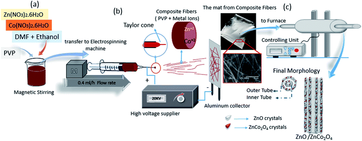
In a typical procedure, to synthesize ZnO/ZnCo2O4 composite nanomaterials, an immiscible solution was formed by mixing ethanol/DMF/metal salts/PVP reagents. In the first step, 0.8 g zinc nitrate was dissolved in mixed 10 ml ethanol absolute and DMF (1![[thin space (1/6-em)]](https://www.rsc.org/images/entities/char_2009.gif) :
:![[thin space (1/6-em)]](https://www.rsc.org/images/entities/char_2009.gif) 1 v/v) followed by magnetic stirring for 30 min. Then, 0.6 g cobalt nitrate was added to the solution with continued stirring in room temperature for 1 hour to obtain a pink solution. In the second step, 1.5 g PVP was slowly added to the previous solution, followed by magnetic stirring for 3 hours in 60 °C to adjust the percentage of water inside the electrospun solution.1 All steps are detailed in Fig. 1(a).
1 v/v) followed by magnetic stirring for 30 min. Then, 0.6 g cobalt nitrate was added to the solution with continued stirring in room temperature for 1 hour to obtain a pink solution. In the second step, 1.5 g PVP was slowly added to the previous solution, followed by magnetic stirring for 3 hours in 60 °C to adjust the percentage of water inside the electrospun solution.1 All steps are detailed in Fig. 1(a).
2.3 Electrospinning process
The electrospinning process is presented in Fig. 1(b), where the as-prepared polymer–metal salts solution were taken up by plastic syringe (1 ml). Electrospinning parameters were chosen from the details of previous experiments, which are suitable to produce fine composite metal oxide nanofibers via single-capillary electrospinning machine. A high voltage of 20 kV was applied between the needle of the syringe and the collector. The distance between the collector and the needle was determined to be about 20 cm. The flow rate was adjusted at 0.4 ml h−1 to produce composite nanofibers consisting of polymer matrix and metal ions. The mats from the composite nanofibers were removed from the collector's surface and placed in a ceramic boat ready for calcination.2.4 Calcination process
The as-prepared composite nanofibers were dried in an autoclave at 60 °C for 10 hours to facilitate removal from the collector surface and enhance evaporation of the chemical solvents. A programmable furnace was used for calcination. To form the tube in tube structure, a heat treatment program with medium heating ratio (Δt) was applied. The mats were calcined for 100 minutes at 450 °C with a heating ratio of 3 °C min−1 in air atmosphere. The calcination process and the potential morphology of ZnO/ZnCo2O4 tube in tube nanostructures are shown in Fig. 1(c). The heating ratio plays a key role in the final shape of the nanofibers, where the structure is directly influenced by the change of heating ratio.5,6 The formation of tube in tube structure can be divided into two steps during the calcination process: in the first step a rod in tube structure will form, where a rigid layer forms on the outer surface of the composite fibers (metal ions/PVP) because of exposure to a large temperature gradient. On heating, owing to the loss of organic components, the inner gel-like viscoelastic core is intensively shrunk. The rigid layer is believed to act as a framework against shrinkage of the outer layer. In this step, it can be seen that two forces from opposite directions act at the same time on the PVP/metal oxide layer between the rigid layer in the surface and the inner core. One is the contraction force, induced by decomposition of the organic component, which promotes shrinkage of the PVP/metal oxide core. The second force is the adhesive force derived from the rigid layer in the surface, which prevents its inward contraction.5 With a sufficiently high temperature and an appropriate heating rate, the PVP/metal oxide layer can be split into a shell (outer tube) and inner core. In the second step, with a high heating ratio and small quantity of PVP/metal oxide in the inner core, the same process will occur to convert it to inner tube. In this case the contraction force is not sufficient to resist the adhesive force and the inner core is pulled to the outer layer to generate the inner tube. The interaction between contraction force and adhesion force, in addition to the influence of the kinetic diffusion of metal cations are the main previous observations.6 Finally, the tube in tube nanostructure is generated after complete removal of all the organic components.52.5 Characterization
Crystallinity of the as-synthesized material was characterized by X-ray powder diffraction (XRD, Rigaku TTR-III) with high intensity. Cu Kα radiation (λ = 0.15406 nm) was operated at 40 kV and 150 mA. The morphology and microstructure of the as-prepared nanomaterials were determined by scan electron microscopy (SEM, JOEL JSM – 6480A), which was operated at an accelerating voltage of 20 kV. Transmission electron microscopy (TEM) and high resolution transmission electron microscopy (HRTEM) images were recorded on a transmission electron microscope (FEITEM, Tecnai G220S-Twin) at accelerating voltages of 120 and 200 kV, respectively. The specific surface area and mesoporous structure of ZnO/ZnCo2O4 tube in tube nanostructure were determined by a single point Brunauer–Emmett–Teller (BET) equation using a micrometrics ASAP 2010 M instrument at liquid nitrogen temperature. Nitrogen adsorption–desorption isotherm analysis was carried out to calculate the pore size distribution using the Barrett–Joyner–Halenda (BJH) model. The surface chemical analysis was recorded by X-ray photoelectron spectroscopy (XPS, Thermo ESCALAB 250Xi).2.6 Fabrication of gas sensors
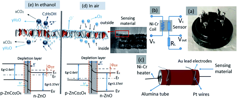
The sensors from as-synthesized gas sensing material were prepared by dispersing an appropriate amount of ZnO/ZnCo2O4 tube in tube nanostructure in absolute ethanol in agate mortar. The solution was shortly sonicated to form a homogenous paste. As-prepared paste was coated onto an alumina tube's outer surface using a special brush. The alumina tube was 1.2 mm in outer diameter, 0.8 mm inner diameter and 4 mm length. The alumina tubes with cover from sensing material were dried at room temperature for 1 day, and in autoclave for 3 hours at 150 °C, to improve stability and ensure evaporation of ethanol and reproducibility of the gas sensing material.10 The next step was to insert electronic elements into the sensors, where a pair of gold electrodes was connected to Pt (platinum) wires. After that a Ni–Cr alloy coil, was fixed inside the alumina tube to control the operating temperature of sensor, as illustrated in Fig. 9(c). The measurements of as-prepared sensors were evaluated using a RQ-2 gas sensing characterization system. Gas sensing experiments were completed using a commercial NMDOG Multifunctional Precision Sensor Analysis Tester (Changsha Dingcheng Scientific Instrument Co, Ltd, Hunan, China). A photograph image of the as-prepared gas sensors is presented in Fig. 9(a).2.7 Principle of gas sensor testing and measurements
The principle of gas sensor testing depends on measuring the change in the circuit resistance between the fresh air atmosphere and the test gas atmosphere.23 In a typical process, a heating voltage (Vh) is supplied by the Ni–Cr alloy coil to control the operating temperature of sensors, the circuit voltage (Vc) is provided via the load resistor (RL) and sensor, which are connected in series system. The signal voltage (Vout) through the load was detected, which changes according to the types and concentrations of the testing gases.24 A schematic diagram of the test circuit is presented in Fig. 9(b). The gas sensing properties in test gas atmosphere of as-prepared sensors were measured by placing them into a closed bottle (10![[thin space (1/6-em)]](https://www.rsc.org/images/entities/char_2009.gif) 000 ml), which contained a trace of test gas vapor after recording of response in air atmosphere. The test gas vapor was injected into the closed bottle using a micro-syringe. The response (R) is defined as ratio of resistance in air atmosphere (Ra) to resistance in test gas atmosphere (Rg), (R = Ra/Rg).25 The response and recovery times are calculated as the period of time that the resistance of sensor changes to 90% of the entire resistance during exposure to test gas and retrieval from the test gas environment, respectively.19,24
000 ml), which contained a trace of test gas vapor after recording of response in air atmosphere. The test gas vapor was injected into the closed bottle using a micro-syringe. The response (R) is defined as ratio of resistance in air atmosphere (Ra) to resistance in test gas atmosphere (Rg), (R = Ra/Rg).25 The response and recovery times are calculated as the period of time that the resistance of sensor changes to 90% of the entire resistance during exposure to test gas and retrieval from the test gas environment, respectively.19,24
3. Results and discussion
3.1 Structural and morphological characteristics
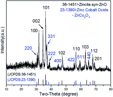
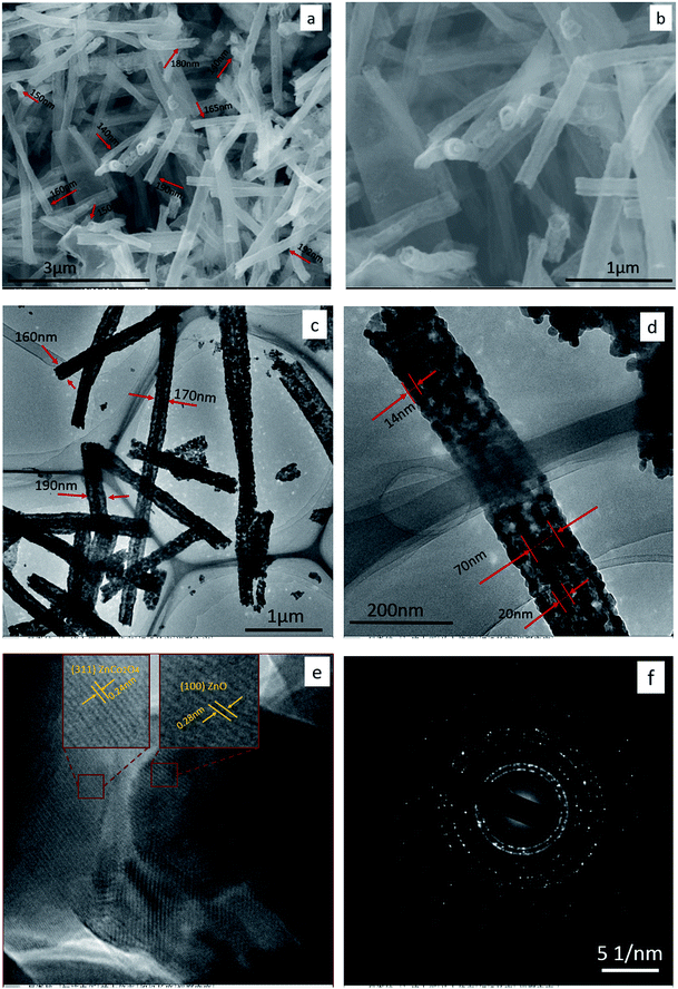
The crystal structure of as-synthesized material was identified by XRD analysis, is shown in Fig. 2. The diffraction peaks 100, 002, 101, 102, 110, 103, 112, and 201 are clearly indexed to the hexagonal wurtzite ZnO crystals, consistent with values in the standard card (JCPDS card no. 36-1451 zincite. syn). The existence of ZnCo2O4 crystals in the structure was demonstrated by the appearance of peaks 220, 331, 222, 400, 422, 511, and 440, which are in good agreement with the standard card of spinel cubic ZnCo2O4 (no. 23-1390 zinc cobalt oxide). The XRD results indicate that the Zn–Co precursors have transformed into ZnO and ZnCo2O4 crystals completely after the calcination process.2,4,10,18 The sharp and strong peaks indicate that the crystallized sample is well ordered. No peaks derived from any other impurities were detected, which confirmed the high purity of the as-prepared material.The initial morphologies of as-prepared ZnO/ZnCo2O4 tube in tube nanostructure were demonstrated by scan electron microscopy (SEM), transmission electron microscopy (TEM), and high resolution transmission electron microscopy (HRTEM), as shown in Fig. 3. Fig. 3(a) and (b) show SEM images of ZnO/ZnCo2O4 tube in tube nanostructure with low and high magnification, respectively. A complex one-dimensional tubular nanostructure consisting of two tubes united in axis is clearly observed, with the outer tube's diameter in the range 150–200 nm. A smooth surface was detected on the as-prepared tube in tube nanostructure. Typical TEM images of ZnO/ZnCo2O4 tube in tube nanostructure with low and high magnification are presented in Fig. 3(c) and (d), respectively. The unique hollow morphology with double shell is clearly confirmed, with outer tube diameter ranging from 150 to 200 nm and thickness of wall about 14 nm, whereas the inner tube diameter is about 70 nm with thickness of wall about 20 nm. High resolution transmission electron microscopy (HRTEM) image is exhibited in Fig. 3(e), with the polycrystalline structure of ZnO/ZnCo2O4 tube in tube nanostructure clearly observed. The lattice fringes are clearly shown with spacing fringes of 0.28 nm and 0.24 nm, which match well with the crystal planes (100) and (311) of wurtzite ZnO and spinel cubic ZnCo2O4 crystals, respectively. The corresponding selected area electron diffraction (SAED) pattern is shown in Fig. 3(f). The SAED pattern confirmed the polycrystalline structure of ZnO/ZnCo2O4 tube in tube nanostructure. In addition, the diffraction rings are compatible with wurtzite ZnO and spinel cubic ZnCo2O4 crystals.
(The diameters and the dimensions were measured using Image J software, with diameters calculated as the average of 50 tubes.)
To confirm the porosity of structure and distribution of pore-size in ZnO/ZnCo2O4 tube in tube nanostructure, N2 adsorption–desorption curves and pore-size distribution curve were constructed. Large specific surface area was observed of the as-prepared tube in tube nanostructure. Fig. 4 shows the adsorption–desorption curves of ZnO/ZnCo2O4 tube in tube nanostructure, with the specific surface area evaluated at about 96.404 m2 g−1. The isothermal curve can be categorized as IV-type with hysteresis loop, which indexes to mesoporous structure of ZnO/ZnCo2O4 tube in tube.2 Pore-size distribution based on the BJH method was calculated, as presented in the inset of Fig. 4. Very fine pores of radius about 19.15 Å are clearly observed in the structure of as-prepared material, with pore volume of 0.162 cm3 g−1. The BET observations are in good agreement with the SEM and TEM results, confirming the mesoporous structure of ZnO/ZnCo2O4 tube in tube with large specific surface area. All the as-reported characteristics are very desirable in gas sensing materials.
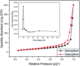 | ||
| Fig. 4 N2 adsorption–desorption isothermal curves of ZnO/ZnCo2O4 tube in tube nanostructure. Inset, pore-size distribution curve of as-prepared material. | ||
The chemical status and surface elemental composition of the as-obtained material nanostructure ZnO/ZnCo2O4 tube in tube were investigated by XPS analyses. To complement the XRD results, XPS spectra of as-prepared material were constructed (Fig. 5). The survey spectrum of ZnO/ZnCo2O4 tube in tube nanostructure is shown in Fig. 5(a), which confirms the existence of Zn 2p, Co 2p, and O 1s chemical states in the surface of the as-obtained material. Fig. 5(b) shows the high resolution spectrum of the Zn 2p state, with two strong peaks located at 1044.2 and 1021.2 eV clearly observed, attributed to the Zn 2p1/2 and Zn 2p3/2 orbits of Zn 2p, respectively. As a result, the presence of Zn(II) oxidation state was confirmed.2 The high resolution spectrum of Co 2p is exhibited in Fig. 5(c), with existence of the Co(III) oxidation state of Co 2p in the surface's sample demonstrated by detection of two peaks of binding energy values at 794.3 and 779.2 eV, which correspond to the Co 2p1/2 and Co 2p3/2 spin–orbits, respectively.26 The high resolution spectrum of oxygen (O 1s) is displayed in Fig. 5(d). From Fig. 5(d) it can be observed that the O 1s peaks are asymmetric, and can be dissolved into three peaks that indicate the presence of several chemical states located at different binding energies. Peaks at binding energies of 532.5, 530.8, and 529.3 eV were detected in the O 1s spectrum, attributed to chemisorbed oxygen species (Oc) at the surface of as-obtained nanomaterial, oxygen vacancies (Ov) in the structure of ZnO/ZnCo2O4, and the lowest binding energy corresponds to oxidized metal ions (lattice oxygen (Ol)),15 respectively. Large presence of Ov is very important in gas sensing materials, as this provides more active sites on the surface of gas sensors to react with oxygen molecules. A large amount of Oc at the surface of sensing materials has a critical influence, in that many surface chemisorbed oxygen species can participate in oxidation reactions on the surface of sensing materials.24 Based on the above observation, it is concluded that the as-synthesized nanomaterial is composed of Zn, Co, and O elements, and that they exist on the surface of ZnO/ZnCo2O4 tube in tube nanostructure in Zn 2p, Co 2p, and O 1s chemical states, respectively.
 | ||
| Fig. 5 XPS spectra of ZnO/ZnCo2O4 tube in tube nanostructure: (a) survey spectrum, (b) Zn 2p spectrum, (c) Co 2p spectrum, and (d) O 1s spectrum. | ||
3.2 The gas sensing performances
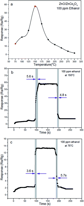
To explore the potential application of ZnO/ZnCo2O4 tube in tube nanostructure, sensors from as-synthesized material were fabricated to determine their gas sensing performance toward various types of VOCs.The main important parameter of gas sensing materials is the operating temperature, which has great influence on the sensing performance.3,27 The response of ZnO/ZnCo2O4 tube in tube nanostructure sensors to various types of VOC gases were investigated in a range of temperature from 75 °C to 300 °C. Fig. 6(a) shows gas response to operating temperature of as-prepared sensors to 100 ppm ethanol. The initial response was increased with operating temperature, until the highest response was reached at 150 °C in the experimental conditions. Such increase in response with temperature mainly results from enhanced oxidation reaction between the gas molecules and sensing materials. The hollow-tubular structure, composite structure, and n–p heterostructure facilitate an increase of adsorbed oxygen on the surface of the material and the gas molecules overcome the activation energy barrier of the depletion layer.1,27 After achieving the highest response value, a gradual decline in response is observed. This decrease in response at high temperature might be caused by a decrease in active sites,3 escape of test gas molecules before their reaction, and self-oxidation of gas molecules.1 Therefore, the optimal temperature for the ZnO/ZnCo2O4 tube in tube nanostructure was determined as 150 °C, with a response of 58 has recorded toward 100 ppm ethanol at operating temperature (150 °C) of as-tested sensors (Fig. 6(b)). Research has concentrated on decreasing the working temperature of gas sensor, and it is worth noting that a response of 13 was detected using the as-tested sensor at 75 °C, because of the large specific surface area and heterostructure. The single cycle response and recovery behavior of the as-tested sensor at 75 °C is presented in Fig. 6(c).
The response and recovery characterizes basic parameters for excellent gas sensors. When the gas sensors are exposed to gas molecules, it is necessary to have rapid response and recovery behavior toward trace gas vapors in practical applications. Response and recovery times of ZnO/ZnCo2O4 tube in tube nanostructure of 100 ppm ethanol at 150 °C and 75 °C are highlighted in Fig. 6(b) and (c), respectively. Fast response and recovery times of the as-prepared sensor to 100 ppm ethanol at optimal temperature were observed, the response and recovery times at optimal temperature are 5.6 s and 4.8 s, respectively. At 75 °C test temperature, the response and recovery times are 3.6 s and 5.7 s, respectively. In conclusion, the adsorption and desorption processes have been quickly completed on the surface of the gas sensing material.17 Large specific surface of as-synthesized tube in tube nanostructure, providing a sufficient number of active sites, can facilitate fast response and recovery characteristics.3
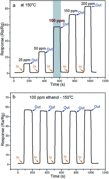
An advantage of gas sensor materials is to have a linear function between the response and test gas concentration.17 A dynamic response of the ZnO/ZnCo2O4 tube in tube nanostructure under gas concentrations in the range 25 ppm to 200 ppm ethanol at optimal temperature is shown in Fig. 7(a). The response of ZnO/ZnCo2O4 tube in tube nanostructure can be enhanced with increasing gas concentration. In the meantime, the as-prepared material exhibited excellent gas sensing behavior to a wide range of ethanol concentrations. A remarkable response of 12 at the optimal temperature of 25 ppm ethanol was observed. These results enhance the influences of the heterostructure ZnO/ZnCo2O4 and the complex-tubular structure on the gas sensing properties.28
Reproducibility and stability are also very important characteristics of gas sensors, and are required from gas sensors for long life service-term and the ability to respond successfully to test gases without a visible decrease in sensor response.27 Fig. 7(b) presents five reversible response cycles of the ZnO/ZnCo2O4 tube in tube nanostructure of 100 ppm ethanol at 150 °C. The observation from Fig. 7(b) enhances the outstanding stability of the as-prepared gas sensor and the reversion of the adsorption–desorption processes of ethanol on the ZnO/ZnCo2O4 tube in tube nanostructure.
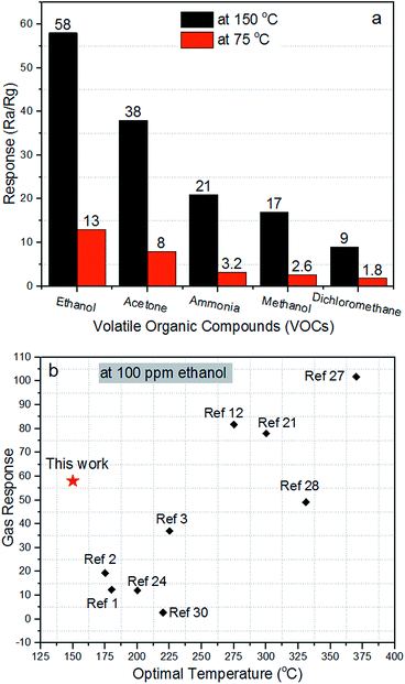
Selectivity is a critical parameter of gas sensors for their potential applications. The gas sensing properties of ZnO/ZnCo2O4 tube in tube nanostructure toward ethanol (CH2CH3OH), acetone (CH3COCH3), ammonia (NH3), methanol (CH4), and dichloromethane (DCM, CH2Cl2) were examined. Fig. 8(a) reveals the response of ZnO/ZnCo2O4 tube in tube nanostructure of 100 ppm concentration toward various types of VOCs (ethanol, acetone, ammonia, methanol, and dichloromethane) at 150 °C and 75 °C. The as-prepared material presents greatly improved response toward ethanol than other test gases at the optimal temperature and at 75 °C. The responses were 58, 38, 21, 17 and 9 at the optimal temperature of ethanol, acetone, ammonia, methanol and dichloromethane, respectively. And it is noteworthy that at 75 °C the responses were 13, 8, 3.2, 2.6 and 1.8 for ethanol, acetone, ammonia, methanol, and dichloromethane, respectively. These observations highlight the excellent selectivity toward ethanol over the other gases at 150 °C and 75 °C. The n–p heterojunction has a critical effect on the selectivity of gas sensing materials.19
A comparison between the gas sensing properties of ZnO/ZnCo2O4 tube in tube nanostructure and that described in the literature toward 100 ppm ethanol is shown in Fig. 8(b). The comparison shows that the ZnO/ZnCo2O4 tube in tube nanostructure exhibited a higher gas sensing response and a lower operating temperature toward 100 ethanol than those reported in the literature, confirming the as-explained properties of ZnO/ZnCo2O4 tube in tube nanostructure and its suitability for detecting ethanol in low operating temperature and high sensitivity.
4. Gas sensing mechanism
It is well-known that the gas sensing performance of semiconductor metal oxides is basically influenced by the electrical conductivity,24 and the capacity for adsorbing–desorbing oxygen ions of the gas sensing materials.28 The gas sensing mechanism of metal oxide sensors depends on the change in the resistance (or conductivity) of sensors during the exposure of test gas molecules and their reaction on the surface of gas sensing materials.2 In the first case, when the gas sensors are exposed to the ambient air, the oxygen molecules (named free state O2) are diffused and adsorbed onto the surface of the gas sensing materials, with the result that they become oxygen ions (O−) by capture of electrons from the conduction band (CB) of the sensing materials to form adsorbed oxygen species. This causes a decrease in the electron concentration on the surface of gas sensing materials, and, as a consequence, a depletion layer is generated on the surface of sensing materials. Hence, the resistance of sensing materials will increase.1 However, when the sensors are in ambient ethanol at the optimal temperature, the ethanol molecules will react with the adsorbed oxygen ions on the surface of sensing materials. This reaction leads to release of the trapped free electrons back into the conduction band of the sensor materials, and therefore a decrease is observed in the resistance of sensing materials. This operation will be repeated each time the sensors are exposed to a new environment.15In this work, two types of semiconductor crystals exist inside the heterostructure of ZnO/ZnCo2O4 tube in tube nanostructure. As previously reported, ZnO is a n-type semiconductor with a band gap at around 3.37 eV, thus the charge is carried by the electrons.21 Whereas ZnCo2O4 is a typical p-type semiconductor oxide with band gap at about 2.6 eV, and for p-type semiconductors the free holes carry the charges.2 From the previous information, it is concluded that the as-prepared ZnO/ZnCo2O4 tube in tube nanostructure has an n–p heterostructure, and because the ZnO is the main component in the structure, the typical results of n-type semiconductor behavior are observed.1,10 Fig. 9(a) presents a photograph image of the as-prepared sensor from ZnO/ZnCo2O4 tube in tube nanostructure. Fig. 9(b) shows the test circuit of gas sensors, which consists of a Ni–Cr coil, a load resistor, and a sensor. The elements of the sensor are presented in Fig. 9(c), which are a ceramic tube, two Au electrodes fixed on the sides, and two rolls of Pt wires.
In the process, the heating voltage (Vh) provided by the Ni–Cr coil controls the testing temperature of sensor, and the sensor and the load resistor (RL) supply the circuit voltage (Vc). The signal voltage (Vout) across the load resistor changes according to the resistance in the sensor's circuit during exposure of the sensor to different environments. The gas sensing mechanism of ZnO/ZnCo2O4 tube in tube nanostructure in ambient air and ambient ethanol, and the change in the energy band gap structure in each ambient are illustrated in Fig. 9(d) and (e), respectively. When the as-prepared gas sensors are exposed to ambient air, the free oxygen molecules will be adsorbed onto sensing material of the gas sensor, then they will capture electrons from the conductive band of sensing materials. As result, the oxygen molecules will decompose to an ionic state, where oxygen molecules can exist in different ionic states (O2− at low temperature, and O− and O2− at high temperature15). In this situation, the concentration of the electrons in the surface layer of the ZnO crystals is low, whereas the concentration of the holes in the surface layer of ZnCo2O4 crystals is very high. Because of the differences between the concentrations of the electrons and holes (charge carriers), a thick depletion layer is formed on the ZnO side, and a high barrier is generated between the different crystals, which cause an increase in the resistance of gas sensing materials (Fig. 9(d)). As Φeff is the effective junction barrier height, Ec is the lower level of the effective junction of the conduction band gap, Ev is the upper level of valence band, and Ef is the Fermi level.3 In the ambient ethanol, when the sensing materials come into contact with the ethanol molecules, the electrons trapped in ionized oxygen species are released back to the conductive band, and a decrease of the concentration of holes in ZnCo2O4 and an increase in electrons concentration in the conductive band of ZnO are detected. The thickness of the depletion layer is thinner than in the ambient air. In consequence, the height of the junction barrier between the n–p interfaces will be decreased, resulting in a decrease in resistance of the sensors. Thereby, a rise in conductivity will be obtained. The entire reaction process and the changes in the energy band are illustrated in Fig. 9(e). The reaction process of ethanol molecules on the surface of ZnO crystals and ZnCo2O4 crystals can be described according to eqn (1) and (2), respectively:1,2
| C2H5OH + 6O2− → 2CO2 + 3H2O + 12e− | (1) |
| C2H5OH + 6O2− + 12h+ → 2CO2 + 3H2O | (2) |
It is worth noting that in the as-prepared materials there are more types of the junctions between the phases, where the n–p junction exists between the ZnO and ZnCo2O4 phases, between the ZnO phases there are n–n junctions, and p–p junctions exist between the ZnCo2O4 phases.29 The existence of p–p and n–n junctions enhances the selectivity of gas sensing materials toward certain test gases, because they have opposite pathway directions. The n–p and p–n junctions have the same pathway direction, which will improve the sensitivity of gas sensors. In fact, all the types of junctions influence the gas sensing performance and this should be taken into consideration during design and synthesis of gas sensing materials.1 Finally, it is concluded that many factors affect the gas sensing properties of ZnO/ZnCo2O4 tube in tube nanostructure. The structure characteristics are important in that the tubular-mesoporous structure provides a large specific surface area (BET results), comprising a huge number of active sites at which oxygen can react with gas molecules30 thus increasing the capacity of gas sensing materials to adsorb oxygen ions on the surface.3 The response and recovery times are affected by the decomposition rate and the decomposition temperature of the adsorbed molecules on the surface of gas sensing materials.1 The type of the junction between the phases plays an important role in the selectivity and response of gas sensing materials.29 The gas sensing materials must be chosen with a high density of charge carriers, where the charge carriers (oxygen vacancies) work as electrically and chemically active sites on the surface of semiconductor materials.3 A high capacity for hydrogen storage assists the surface adsorption and diffusion of H2 inside the crystal interstitial sites. And the crystal architecture has a very sensitive effect on the response of gas sensing materials, which influences the number of oxygen vacancies on the surface. Recently spinel crystals have been intensively studied because of their electrochemical and chemisorbent properties.2,4,6 In summary, the reaction between the ethanol molecules and the oxygen vacancies in the depleted layer is enhanced by the mesoporous heterojunction structure of the as-prepared material ZnO/ZnCo2O4 tube in tube nanostructure. Potential reasons for the improvement in the gas sensing properties of ZnO/ZnCo2O4 are offered in the above mechanisms.
5. Conclusions
In this work, ZnO/ZnCo2O4 tube in tube nanostructure was fabricated using single capillary electrospinning technology. The structure and the morphology of the as-prepared tubular material were characterized by XRD, XPS, SEM, TEM, and BET analysis. A complex tubular structure with double shell was confirmed with the diameter of the external tube in the range 150–200 nm and the interior tube about 70 nm. The gas sensing performance of the as-prepared material was investigated and discussed. An excellent response (58) of ZnO/ZnCo2O4 tube in tube nanostructure toward 100 ppm ethanol at the optimal temperature of 150 °C was clearly observed. Rapid response and recovery times of the as-prepared gas sensing material at optimal temperature with high selectivity of ethanol among different types of VOCs were detected. Remarkable gas sensing properties of ZnO/ZnCo2O4 tube in tube nanostructure at 75 °C with response of 13, response time of 3.6 s, and recovery time of 5.7 s were shown. The outstanding gas sensing performance of ZnO/ZnCo2O4 tube in tube nanostructure could be explained by the unique tubular structure, the nanocomposite material, and the mesoporous hollow structure, which enhanced the number of oxygen vacancies in the depleted layer, as well as the reaction between the gas sensing materials and the gas molecules. From these results, it appears that composite ZnO/ZnCo2O4 tube in tube nanostructure has promise in the gas sensing field, although it is also suggested that this material is tested in other fields, such as catalysis and electrochemical fields.Acknowledgements
This work was supported by Fundamental Research Funds of the Central University (HEUCFZ), Natural Science Foundation of Heilongjiang Province (B201404), the Major Project of Science and Technology of Heilongjiang Province (GA14A101), National Natural Science Foundation of China (NSFC 51402065), and International Science & Technology Cooperation Program of China (2015DFR50050).Notes and references
- K. T. Alali, T. Liu, J. Liu, Q. Liu, Z. Li, H. Zhang, K. Aljebawi and J. Wang, RSC Adv., 2016, 6, 101626–101637 RSC.
- T. Liu, J. Liu, Q. Liu, D. Song, H. Zhang, H. Zhang and J. Wang, Nanoscale, 2015, 7, 19714–19721 RSC.
- J. Liu, M. Dai, T. Wang, P. Sun, X. Liang, G. Lu, K. Shimanoe and N. Yamazoe, ACS Appl. Mater. Interfaces, 2016, 8, 6669–6677 CAS.
- G. Zhou, J. Zhu, Y. Chen, L. Mei, X. Duan, G. Zhang, L. Chen, T. Wang and B. Lu, Electrochim. Acta, 2014, 123, 450–455 CrossRef CAS.
- K. R. Yoon, G. Y. Lee, J. W. Jung, N. H. Kim, S. O. Kim and I. D. Kim, Nano Lett., 2016, 16, 2076–2083 CrossRef CAS PubMed.
- S. peng, L. Li, Y. Hu, M. Srinivasan, F. Cheng, J. Chen and S. Ramakrishna, ACS Nano, 2015, 9, 1945–1954 CrossRef CAS PubMed.
- T. Wetchakuna, T. Samerjai, N. Tamaekonga, C. Liewhirana, C. Siriwonga, V. Kruefua, A. Wisitsoraatb, A. Tuantranontb and S. Phanichphant, Sens. Actuators, B, 2011, 160, 580–591 CrossRef.
- S. Wei, Y. Yu and M. Zhou, Mater. Lett., 2010, 64, 2284–2286 CrossRef CAS.
- T. Senthil and S. Anandhan, J. Colloid Interface Sci., 2014, 432, 285–296 CrossRef CAS PubMed.
- X. Zhou, W. Feng, C. Wang, X. Hu, X. Li, P. Sun, K. Shimanoe, N. Yamazoe and G. Lu, J. Mater. Chem. A, 2014, 2, 17683–17690 CAS.
- M.-Y. Guan, D.-M. Xu, Y.-F. Song and Y. Guo, Sens. Actuators, B, 2013, 188, 1148–1154 CrossRef CAS.
- B. Huang, C. Zhao, M. Zhang, Z. Zhang, E. Xie, J. Zhou and W. Han, Appl. Surf. Sci., 2015, 349, 615–621 CrossRef CAS.
- H. J. Park, J. Kim, N. J. Choi, H. Song and D. S. Lee, ACS Appl. Mater. Interfaces, 2016, 8, 3233–3240 CAS.
- X. Yu, F. Song, B. Zhai, C. Zheng and Y. Wang, Phys. E, 2013, 52, 92–96 CrossRef CAS.
- W. Li, S. Ma, Y. Li, G. Yang, Y. Mao, J. Luo, D. Gengzang, X. Xu and S. Yan, Sens. Actuators, B, 2015, 211, 392–402 CrossRef CAS.
- S. S. Mali, H. Kim, W. Y. Jang, H. S. Park, P. S. Patil and C. K. Hong, ACS Sustainable Chem. Eng., 2013, 1, 1207–1213 CrossRef CAS.
- M. Farbod, M. H. Joula and M. Vaezi, Mater. Chem. Phys., 2016, 176, 12–23 CrossRef CAS.
- Z. Zhang, X. Li, C. Wang, L. Wei, Y. Liu and C. Shao, J. Phys. Chem. C, 2009, 113, 19397–19403 CAS.
- S. H. Yan, S. Y. Ma, X. L. Xu, W. Q. Li, J. Luo, W. X. Jin, T. T. Wang, X. H. Jiang, Y. Lu and H. S. Song, Mater. Lett., 2015, 159, 447–450 CrossRef CAS.
- Y. Sun, Z. Zhao, P. Li, G. Li, Y. Chen, W. Zhang and J. Hu, Appl. Surf. Sci., 2015, 356, 73–80 CrossRef CAS.
- S. H. Yan, S. Y. Ma, W. Q. Li, X. L. Xu, L. Cheng, H. S. Song and X. Y. Liang, Sens. Actuators, B, 2015, 221, 88–95 CrossRef CAS.
- J. Zhang, J.-M. Song, H.-L. Niu, C.-J. Mao, S.-Y. Zhang and Y.-H. Shen, Sens. Actuators, B, 2015, 221, 55–62 CrossRef CAS.
- N. F. Hamedani, A. R. Mahjoub, A. A. khodadadi and Y. Mortazavi, Sens. Actuators, B, 2012, 169, 67–73 CrossRef CAS.
- C. Wang, X. Cui, J. Liu, X. Zhou, X. Cheng, P. Sun, X. Hu, X. Li, J. Zheng and G. Lu, ACS Sens., 2016, 1, 131–136 CrossRef CAS.
- A. Katoch, Z. Ul Abideen, H. W. Kim and S. S. Kim, ACS Appl. Mater. Interfaces, 2016, 8, 2486–2494 CAS.
- F. Wang, X. Wang, D. Liu, J. Zhen, J. Li, Y. Wang and H. Zhang, ACS Appl. Mater. Interfaces, 2014, 6, 22216–22223 CAS.
- J. Ding, J. Zhu, P. Yao, J. Li, H. Bi and X. Wang, Ind. Eng. Chem. Res., 2015, 54, 8947–8953 CrossRef CAS.
- Y. Liu, P. Yang, J. Li, K. Matras-Postolek, Y. Yue and B. Huang, RSC Adv., 2015, 5, 98500–98507 RSC.
- Y. Liu, X. Sun, B. Li and Y. Lei, J. Mater. Chem. A, 2014, 2, 11651 CAS.
- W. Zeng, W. Chen, Z. Li, H. Zhang and T. Li, Mater. Res., 2015, 65, 157–162 CAS.
| This journal is © The Royal Society of Chemistry 2017 |

