 Open Access Article
Water desalination using nano screw pumps with a considerable processing rate
LiYa Wang,
HengAn Wu and
FengChao Wang *
*
CAS Key Laboratory of Mechanical Behavior and Design of Materials, Department of Modern Mechanics, CAS Center for Excellence in Nanoscience, University of Science and Technology of China, Hefei, Anhui 230027, China. E-mail: wangfc@ustc.edu.cn; Tel: +86-551-6360-1238
First published on 7th April 2017
Abstract
The ability of a nano screw pump (NSP) to reject salt ions while conducting fast water flow makes it an ideal candidate as a desalination device. In this work, the desalinating performances of NSPs due to the influence of screw radius, screw pitch, and the number of the screw pitch were investigated using molecular dynamics (MD) simulations. Our results demonstrate that, on the one hand, a narrow screw pitch blocks the passage of hydrated ions, as extra energy is needed for dehydration. On the other hand, a considerable water flux can be obtained by increasing the screw diameter without losing the capability for salt rejection. The mechanisms of water transport through NSPs can be explained by the synergistic effect of confinement resistance and pitch-dependent water transport modes, while the latter factor plays a more dominant role. Water flux is further improved by decreasing the screw pitch number, which can not only decrease the confinement resistance but also facilitate a faster water transport mode. The excellent desalination properties validate NSP as a promising nanofluidic device for water desalination, purification and separation. This work can also provide useful guidelines for the design of other desalinating nanodevices.
1. Introduction
Nowadays, water desalination has proved to be one of the most promising approaches to deal with the growing shortage of fresh water.1–5 Salt rejection and water permeability are two equally important factors that dominate the desalinating behavior.6–9 Among various desalination techniques, reverse osmosis (RO) is most commonly used due to its low energy input compared with other methods like thermal desalination.10–12 In the RO desalination process, salty water is forced to pass through a semipermeable membrane that allows the passage of water but blocks ions. As the most crucial component, the membrane properties determine the performance of water desalination.13–17 For the conventional RO membranes, such as polymers and zeolites, studies suggest that their relatively low water permeability may pose a challenge for desalination applications.8,13,18 Recently, graphene-based materials have emerged as potential candidates with excellent desalination characteristics.19–24 Through deliberately creating water pathways, the monolayer or multilayer nanoporous graphene and stacked graphene oxide layer membrane exhibit extraordinary desalination capability.25,26 The ultrathin multilayer nanoporous graphene membrane possesses extremely high water permeation, which is several orders of magnitude higher than the existing RO membranes.8,9At the nanoscale, carbon nanotube (CNT) is frequently utilized as nanochannel due to its unique properties.27–32 Studies revealed that water flow through CNTs is considerably higher than expectations derived from continuum hydrodynamic theory, which would provide an ideal basis for desalination if high salt rejection could also be achieved.30,33 To date, two kinds of strategies have been adopted to prevent the passage of salt ions. One is creating confined space by decreasing the CNT radius. It has been demonstrated that for CNTs greater in diameter than 1.0 nm, there is unlikely to be a sizable barrier to limit the permeability of salt ions.6 Additionally, chemical modifications allow the salt ions to be rejected through the electrostatic repulsion.34 Functionalized CNTs exhibit improved capability of salt rejection with chemical groups decorated on the edge or interior surface.28,29 However, notable drawback of the aforementioned techniques lies in that it has to trade off against the rapid water flow.7 The inevitable compromise between water flux and salt rejection greatly reduces the availability of CNTs for water desalination. Consequently, a series of CNT-based nanodevices have been developed to solve this tricky problem.35,36
In our previous work, a nano screw pump (NSP) was designed with a helical nanowire embedded inside an outer nanochannel.37 Helical nanowires with different morphologies have been synthesized in experiments to function solely or work as a component of complex nanodevices.38–43 Encapsulation of nanowires inside silicon oxide sheath, graphene scrolls and CNTs has also been reported and proved feasible in experiments.44–46 The nanowire rotation can be realized by magnetic, optical, electrical and chemical means.38–41,47–52 Nevertheless, we have to indicate here that some specific details of the experimental feasibility need further cautious investigations. Future endeavors are required with regard to assembling the helical nanowires inside nanochannels and driving its steady rotation. Our previous work demonstrated that the unique asymmetry of helical nanowire makes it perfect candidate for unidirectional water pumping.37 Three water transport modes were observed: cluster-by-cluster, pseudo-continuous, and linear-continuous. Particularly, the discontinuous water transport in pseudo-continuous mode dramatically lowers its water flux, as it is energetically unfavorable for water molecules to crack from the whole chain file before escaping from NSP.37 Herein, we have further investigated its potential in water desalination performance. With narrow screw pitch, sodium chloride (NaCl) can be effectively filtered from water based on the steric effect. It has been verified that the mechanisms of water transport through NSP can be explained from the perspective of confinement resistance and pitch-dependent water transport modes. Two strategies have been proposed to acquire superior water flux. The first suggestion is to increase the NSP diameter as long as the screw pitch is narrow enough to block the ions passage. The second possible way is to decrease the screw pitch number. By eliminating extra confinement, the water pumping velocity is significantly increased. Moreover, this operation also relieves the water molecules from the unfavorable pseudo-continuous transport mode and enhances the water permeation indirectly. Through comprehensive evaluations of both salt rejection and water permeability, NSPs with tunable screw pitch are validated to be excellent candidates for water desalination. This work may provide inspirations for the design of other desalinating nanodevices.
2. Simulation model and method
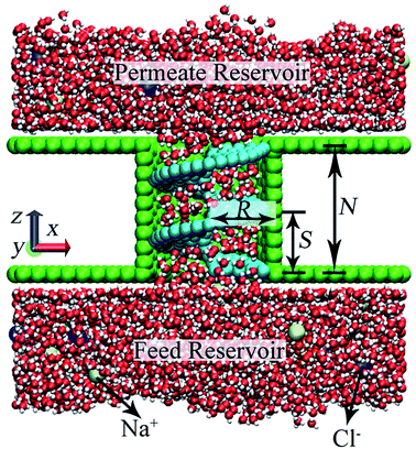
A NSP modeled following our previous methodology is used for water desalination in this work. As for the helical nanowire selection in practical desalinating performances, normal helical wires and helical nanowires with rectangular cross section will be more preferable from the perspective of creating confined space using narrow screw pitch.37 Helical nanowire modeled using minimal number of atoms is still utilized in MD simulations in the convenience of computational resource. To test the desalination capability of NSP, a representative salt solution of NaCl was selected. A net concentration of 0.2 M NaCl solution was yielded with 18 Na+ and 18 Cl− randomly placed in the reservoir with 4816 water molecules. The NaCl solution, which was placed at the feed reservoir initially, is transported to the permeate reservoir by virtue of the rotation of helical blade. A snapshot is shown in Fig. 1 when nearly half of the water molecules on the feed side permeated through the NSP. Desalination performance of NSP was investigated across a wide range of configurational parameters, including the screw radius (R), the screw pitch (S), and the number of screw pitch (N).Water was modeled using the TIP4P/2005 potential,53 while interactions for all other atomic species were modeled using Lennard-Jones (LJ) and coulombic terms. Parameters for graphene, CNT and salt ions were adopted from a previous paper.8 The potential parameters for the rigid helical blade atoms were ε = 0.0859 kcal mol−1 and σ = 3.997 Å. Lorentz–Berthelot mixing rule was used for cross interactions.54 The long-range electrostatic interaction was computed using particle–particle particle–mesh (PPPM) technique.55
Molecular dynamics (MD) simulations were carried out using the LAMMPS package56 to predict the NSPs' desalination performance. Simulations were performed in the constant-volume and constant-temperature (NVT) ensemble at 300 K using a Nose–Hoover thermostat. The equations of motion were integrated using a velocity-Verlet scheme with a time step of 1.0 fs. Periodic boundary conditions were employed in the x and y directions. The non-periodic boundary condition in the z direction characterized our MD system a dead-end filtration system. In order to investigate the steady-state properties of the NSP system, the amount of water that enters the permeate reservoir must be significantly larger than that inside the NSP. Moreover, considering the finite feed reservoir, reasonable statistical interval must be selected to guarantee physical response of water and salt ions. That is to say, a criterion for data collection is needed to estimate salt rejection and water flux rate. In our work, every MD run was marked to end when 4000, over 80% of the water molecules permeated through the NSP. With this setup, on the one hand, it allows the desalinating performance in every case to be fully developed and water molecules are restricted within the range of linear transport. On the other hand, in view of the large screw diameter span, huge water flux rate gap is inevitable. Under this circumstance, it is almost impossible to compare the salt rejection among NSPs with different radii by defining a uniform time standard. In contrast, our data collection criterion has solved this problem and salt rejection comparison can be acquired. Visual molecular dynamics (VMD) was utilized for the visualization of desalination performance inside NSPs.57
3. Results and discussion
3.1 Ions transport
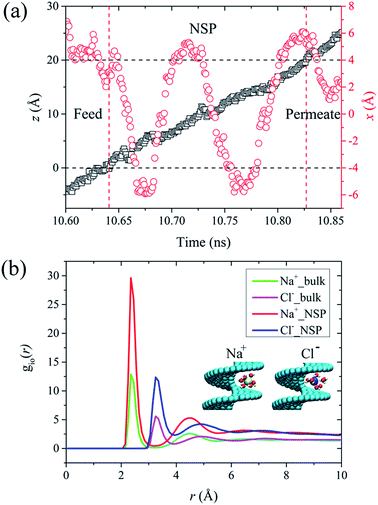
In this section, we take the NSP with radius of 1.09 nm and screw pitch of 1.0 nm to provide a brief overview of ions transport. First of all, the concept of salt rejection was defined. Simulations revealed that the transport of Na+ and Cl− was not exactly simultaneous. However, the ultimate ion permeation is almost the same due to local charge conservation. Hence, the number of salt ions here refers to the average number of Na+ and Cl− ions.9 The salt rejection is defined as the ratio of the remaining ions at the end of the simulation and the initial number of salt ions in the feed reservoir. A higher salt rejection corresponds to a better desalination capability. For a NSP with perfect purification, only water molecules can permeate while salt passage is entirely impeded. The rotating frequency for the blade was set as 0.1256 ps−1. The seemingly dramatically high angular velocity is the characteristic of MD simulations, which allows us to obtain more precise data for water flux and salt rejection in a finite simulation time.35,58The travelling trajectory of a single Na+ is plotted in Fig. 2(a) to intuitively demonstrate the transport details of salt ions. It could be observed that the Na+ moved disorderly in the feed reservoir before entering the NSP, reflected by a series of random walks in the x direction (perpendicular to the channel axis). Once entering the NSP, it started to exhibit nearly symmetric reciprocation motion in the x direction by virtue of the centrifugal force. Corresponding to N = 2, the reciprocation motion of the ion lasted for two cycles in the x direction. Meanwhile, the ion was shifted upwards continuously in the z direction (along the channel axis) in a linear fashion. Compared with the rotating CNT system,35,58 the introducing blade inside CNT overcame the problem of uneven liquid distribution and significantly improved the rotation validity, thus increased the liquid flux. It is noteworthy that the maximum displacement for Na+ in x direction is around 0.6 nm, which is smaller than the screw radius. Thus, we deduced that it might be roomy enough for Na+ to form intact hydration configuration between the helical blades inside the R = 1.09 nm NSP. In order to verify this conjecture, we plotted the ion-oxygen radial distribution functions (RDFs) for two kinds of ions inside NSP and bulk solution in Fig. 2(b). For a certain type of ion, although the profile shape varied, the first maximum and minimum located at the same position. This consistency indicates that the coordination shell sizes of the two kinds of ions are the same under different circumstances. As for the number of water molecules in the hydration shell, simulations revealed that the coordination number (Nc) of Na+ and Cl− inside NSP is the same as that in the bulk solution, which is 5.8 and 7.2, respectively and agrees well with the results given in literatures.59–62 Generally, the coordination number is calculated by the numeric integration of the RDF profiles:
The snapshots of the first hydration shell around the ions inside NSP are demonstrated in the insets of Fig. 2(b). The nearly bulk water structure in R = 1.09 nm and S = 1.0 nm NSP provided more chances for Na+ and Cl− ions between helical blade to be surrounded by ambient water molecules and formed intact hydration configuration. It has been reported that when pore or gap size is smaller than the diameter of hydrated ions, the passage of hydrated ions would be completely blocked, as extra energy is needed to hydrate.15 Under the circumstances, salt rejection based on space confinement is achieved. When the pore or gap size is large enough for the hydrated ions to pass through with less or even no water molecules stripped off, less resistance is exerted on ions permeation and salt rejection capability is undermined.15 In order to confirm the evolution of hydration structure, a sequence of MD simulations has been carried out in the next section to investigate the pitch-dependent behavior of hydrated ions.
3.2 Salt rejection
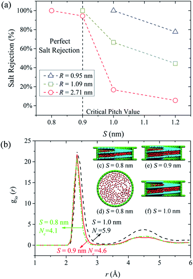
When pristine CNTs are used for water desalination, the diameters need to be small enough to impede the ions passage. It has been reported that a CNT with diameter close to 1.0 nm is already large enough for an ion such as Na+ to enter with complete hydration shell.7 Extremely low water flux is an inevitable result of small diameter, which greatly reduces the desalination efficiency. In this work, we discovered that perfect water desalination can be realized by simply decreasing the screw pitch. The lower water flux resulting from small screw pitch can be compensated by large NSP diameter. More crucially, through tunable screw pitch, limitations on the NSP diameters are not necessary any more. As long as the screw pitch is properly selected to guarantee full salt rejection, the NSP diameter can be as large as possible, and the larger the diameter, the higher water permeation is. The ability of NSP to reject salt ions while conducting fast water flow makes it an ideal candidate as a desalination device.In Fig. 3(a), we demonstrated the salt rejection as a function of screw pitch when the screw radius was 0.95 nm, 1.09 nm and 2.71 nm. A radius as large as 2.71 nm was specially selected here to examine the desalination performance of large NSPs. Salt rejection in three cases exhibited remarkable increase with the decreasing screw pitch. More specifically, 100% salt rejection was obtained when the screw pitch was 0.8 nm, 0.9 nm and 1.0 nm in R = 2.71 nm, 1.09 nm and 0.95 nm NSPs, respectively. For the R = 2.71 nm NSP, through checking the MD snapshots we noticed that water molecules inside the helical blade formed single-layer structures in the S = 0.8 nm. The side and top views of single water layer were illustrated in Fig. 3(c) and (d). In the formation of intact hydration shell, the salt ion is surrounded by water molecules from all around. Assuming that one ion stays inside the S = 0.8 nm helical blade, the single water layer structure will inevitably restrict the number of surrounding water molecules. That is to say, if salt ions want to pass through the NSP under this circumstance, extra energy is needed for dehydration, which subjects the ions passage to large energy barrier and salt rejection depending solely on physical size exclusion mechanisms is realized. For the slightly larger screw pitch (S = 0.9 nm), the highly-ordered double-layer water structure shown in Fig. 3(e) allowed the hydration ion to keep more water molecules around during the transport process, which slightly lowered the energy barrier for hydration ions permeation. Consequently, one salt ion made it through the NSP successfully during the MD simulations, but the salt rejection was still up to 94.4%. When the screw pitch was increased to 1.2 nm, ordered water structure totally vanished inside NSP and water molecules distribution approached that of bulk water. For S = 1.0 nm NSP, the water molecules exhibited a transition state between two-layer water structure and bulk water. The roomy space in the aforementioned two cases allowed the salt ions to pass through easily, and extremely low salt rejection was caused. To verify different extent of ion dehydration, a single Na+ was placed artificially inside salt-rejected NSPs and ion-oxygen RDFs were calculated in Fig. 3(b). Results show that Nc of Na+ are 4.1, 4.6 and 5.9 when S = 0.8 nm, 0.9 nm and 1.0 nm, respectively. As expected, Nc is similar to that in bulk solution when S = 1.0 nm. In spite of minor difference in Nc, study revealed that interaction energy between the ions and its surrounding water molecules changes markedly,59 which is large enough to determine different salt response. Similar trends were observed for the other two NSPs with smaller diameters. Our analysis highlights a critical regime when S is no larger than 0.9 nm, in which the ordered water structures reduced the possibility of forming complete hydrated ions between the narrow screw pitch and almost perfect salt rejection could be realized. Once exceeding this screw pitch value, salt rejection would decrease significantly. Thus, a critical screw pitch of 0.9 nm can be derived here. It should be noted that for the smallest (R = 0.95 nm) NSP, 100% salt rejection could be obtained when the screw pitch was 1.0 nm. Even for S = 1.2 nm NSP, the salt rejection could still reach 80%. This is because other than small screw pitch, small screw radius also serves as a factor that governs the confined space. As emphasis of this work lies in the influence of screw pitch on desalination capability of NSP, only two NSPs with larger radius are considered in the following discussions.
3.3 Water permeation mechanism
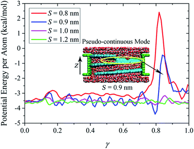
In the measurement of efficiency for a desalination device, other than salt rejection, water permeation is another key element that has to be considered. Here in our work, the first strategy proposed for water flux enhancement is to increase the NSP diameter as long as the screw pitch is narrow enough to block the ions passage. It is anticipated that the water flux will exhibit remarkable increase with the diameter increase. However, as the existence of screw pitch poses extra influence on water transport, the quantitative evolution of water flux with NSP diameter is not within the scope of this study. For NSP with a certain screw radius, water flux drops dramatically with the decrease of screw pitch. Taking the R = 1.09 nm NSP for example, water flux rate can reach over 300 per nanosecond when the screw pitch is over the critical value. But in the S = 0.9 nm NSP when 100% salt rejection is satisfied, the water flux rate falls to only 39 per nanosecond. The contrast is even more remarkable for larger NSP. The water flux rate for the R = 2.71 nm NSP is 2856, 215 and 133 per nanosecond, when the screw pitch is 1.0 nm, 0.9 nm and 0.8 nm, respectively. Water flux is traded off substantially in order to create confined space to hinder the ions passage. To better understand the mechanism of water permeation, we selected the largest NSP model and plotted the potential energy per atom in water molecules along the transport direction in Fig. 4. Normalization is performed on the NSP length to eliminate the influence of different screw pitch. A factor γ is defined as the ratio of position coordinate in z direction and NSP length.According to the potential line, there exists an energy barrier when water enters the NSP. With the increase of screw pitch, the magnitude and extent of the entrance energy barrier decrease, implying that large screw pitch lowers the confinement resistance. Similar trend is observed for water potential energy inside NSP. The large fluctuations inside S = 0.9 nm NSP is proved to be closely related to the highly ordered double-layer water structures, as shown in the inset. Compared with the regular entrance energy barrier, remarkable difference exists among exit energy barriers. For two NSPs with larger screw pitch (S = 1.0 nm and 1.2 nm), an energy barrier with almost the same size as entrance one locates at the exit. However, when the screw pitch is decreased to the extent when ordered water layer structure dominates, extremely high energy barriers show up at the exit. The different morphology of exit energy barriers inspires us to further investigate the underlying mechanism. Through checking the transport process inside NSP with narrow screw pitch, we observe that when water molecules are transported to the last pitch, instead of adsorbing on the hydrophobic blade surface, it is more energetically favorable to be thrown into the upper reservoir directly. As a result, a low water density region is formed in the top pitch, as included in the yellow circle in the inset. For the sake of simplicity, this low water density region is referred to as discontinuous layer in the following discussions. Corresponding to the position of discontinuous layer, extremely high exit energy barrier shows up. Thus, we can conclude that the water transport mode contributes to the striking difference among exit energy barriers. Compared to confinement resistance, pitch-dependent water transport mode plays more dominating role in water permeation.
It has been verified in our previous work that three water transport modes were observed depending on the NSP configuration parameters and blade wettability: cluster-by-cluster, pseudo-continuous, and linear-continuous.37 Here, for NSP with large screw pitch in which bulk water dominates, the last mode works and water flux increases linearly with the rotating speed. However, for the small screw pitch ones, the corresponding water transport mode is pseudo-continuous, as shown in the inset of Fig. 4. The continuous structured water layers can be preserved inside the NSP. When water molecules are transported to the last pitch and no longer confined, they have to break from the water layers in order to escape from the NSP. Due to the energetically costly cracking from water layers, the water flux rate was declined inevitably.
To demonstrate the aforementioned two different water transport modes, water density and velocity profiles inside S = 0.8 nm and S = 1.0 nm NSPs are illustrated in Fig. 5. In the pseudo-continuous transport mode, once water molecules transported to the last pitch are broken from continuous water layers, it is more energetically favorable for water molecules to be thrown into the upper reservoir directly, rather than adsorbing on the hydrophobic blades. The centrifugal force from blade rotation even aggravates this trend. As a result, a discontinuous layer within the range of upper pitch is observed in Fig. 5(a). As for the velocity profiles in Fig. 5(b), water velocity corresponding to the position of discontinuous layer is much higher, which also proves the direct water permeation into the water reservoir instead of adsorbing on the blade surface. While for water molecules confined inside the blade, large resistance due to confinement greatly decreased water velocity and the water molecules flowed at constant velocity. In this sense, the smaller constant velocity before the maximum truly characterizes the water motion inside NSP, as the subsequent water motion does not contribute to determining water flux rate at all. Phenomena are totally different in S = 1.0 nm NSP. The whole density distribution of water molecules is almost homogeneous except a slight decrease at the exit end, but the continuous water flow can still be maintained and no discontinuous layer is observed. Also, the constant velocity of water molecules inside NSP is much higher. Comparing the constant water velocity inside the NSP, it is found that the velocity in the linear-continuous mode is almost ten times higher than that in pseudo-continuous mode, which is a direct reflection of confinement resistance. To summarize, two factors play crucial roles in determining water permeation through NSP: resistance from confinement and pitch-dependent water transport modes.
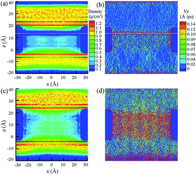 | ||
| Fig. 5 Density and velocity profiles of water flow inside (a and b) S = 0.8 nm and (c and d) S = 1.0 nm NSPs. The white line in (a and b) indicates the position of maximum water velocity. | ||
3.4 Superior water permeation by eliminating invalid confinement
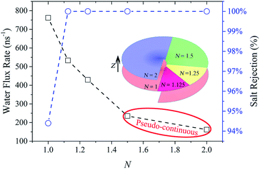
Up to now, complete salt rejection can be realized by decreasing the screw pitch to a certain value which is no larger than the critical screw pitch. However, small screw pitch also creates significant steric hindrance to the passage of water which can be expected to reduce the water flux. How to effectively improve water permeation is still worth further research. After understanding the mechanism of water permeation though NSP, we further improve the water flux by decreasing the number of screw pitch. With this strategy, it not only enhances the water velocity by reducing confinement resistance, but also facilitates a faster water transport mode.MD simulations were carried out using R = 2.71 nm & S = 0.8 nm NSP. In Fig. 6, the evolution of water flux rate and salt rejection with the screw pitch number is illustrated. For simplicity, the blade corresponding to one complete screw pitch is defined as one unit of blade here. The color variation in the inset is adopted to characterize the increase of extra blade units compared with the prior N. Actually, the blade for each N includes the extra blade units and all the below ones along the negative z direction. Thus, when N = 1, 1.125, 1.25, 1.5 and 2, the NSP possesses 1, 9/8, 5/4, 3/2 and 2 units of blade, respectively, as shown in the inset of Fig. 6. First of all, it could be observed that 100% salt rejection was reached and then maintained once N exceeded 1.125. But the water flux rate significantly decreased with the increase of N. In other words, by reducing the number of screw pitch, water flux was raised remarkably. Particularly, when N decreased from 2 to 1.125, water flux rate was increased with an improvement of 229%. When N = 1, in spite of an extremely high water flux rate of 762 per nanosecond, one salt ion passed through the NSP, resulting in 94.4% salt rejection. This was because if ions want to make its way through the N = 1 NSP, it only has to cross a gap with a width of 0.8 nm. As the radius of hydration Na+ and Cl− ion is 0.358 nm and 0.331 nm, respectively, it is possible for salt ions to pass the gap with the hydration shell intact.64 However, the high salt rejection also manifests the existence of high energy barrier. Thus, when extra confinement between adjacent blade units is imposed in other NSPs with N larger than 1, the salt permeation is totally impeded.
From the perspective of reducing confinement resistance for water flow, a concept of ‘effective confinement’ is proposed here. It refers to the least restriction utilized to fully prevent the ions passage. Once full salt rejection is realized, the extra confinement only serves as resistance that weakens the water permeation as 100% salt rejection cannot be further improved. The term ‘effective confinement’ is relative to the extra confinement, which we define as ‘invalid confinement’ in the following discussions. For example, the confined 45° sector area in N = 1.125 NSP is enough to block all salt ions form crossing. Thus, the confinement can be roughly regarded as effective here. 100% salt rejection continues to hold as long as N is no less than this critical value. The extra resistance due to invalid confinement in N = 1.25, 1.5 and 2 NSPs results in dramatically low water flux and thus inefficient water desalination. Superior water permeation can be obtained by eliminating the invalid confinement. This technique can also provide useful guidelines for the design of other confinement-based water desalination devices.
Considering the linearly decreased confinement resistance, it is theoretically reasonable to expect that the water flux rate decrease linearly with N. However, the rapidly declined water flux rate implies that confinement resistance alone is sufficient to explain the influence of N on water permeation, and therefore another factor must be at play. We find that it is the water transport modes that caused this deviation. It is worth noting that the pseudo-continuous water transport mode only exists when N = 1.5 and 2. The absence of this certain water transport mode in NSPs with smaller N improves the water permeation indirectly. Fig. 7(a) and (b) shows the evolution of water velocity and water density with N along the channel axis. Note that normalization is also performed on the screw length here. The key results can be summarized as follows:
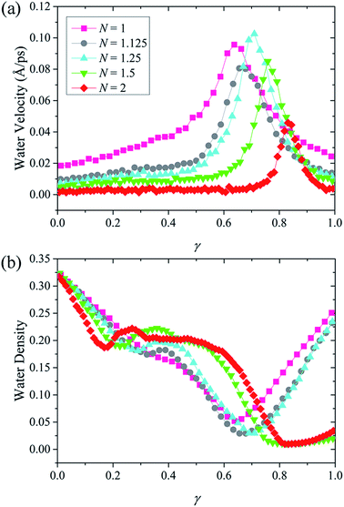 | ||
| Fig. 7 (a) Velocity and (b) density of water molecules inside NSPs with different N along the transport direction. | ||
(1) Less resistance is exerted on water flow with the decrease of N, and the water velocity is increased accordingly. It should be noted that the large volume of hydrated ion makes it response to resistance more sensitively than water molecules. When N is increased to 1.125 and 1.25, it has been verified that the extra confinement between adjacent units of blade is enough to hinder the ions passage. While for water molecules, the effect of confinement resistance is less prominent under these circumstances and the acceleration motion can still be maintained.
(2) For N = 1.5 and 2, stable single-layer water structure occupied the confined space between blade units. Other than the lower water velocity from confinement resistance, the unique pseudo-continuous transport mode even aggravates the low water flux rate.
(3) For other three cases with smaller N, water molecules speed up continuously while crossing the NSP. Saving the trouble of cracking from stable water layers, the water transport is greatly improved. As a result, a relatively high water flux rate can be acquired in spite of discontinuity.
Consistent with the velocity distribution in Fig. 5, when water molecules are transported to the last pitch and escape confinement, a maximum velocity is reached. In fact, it is the velocity before maximum that determines water flux rate. The water velocity in Fig. 7(a) can be interpreted from two aspects. On the one hand, the variation of velocity magnitude before maximum represents the extent of confinement resistance. On the other hand, the constant or accelerating velocity morphology corresponds to different water transport modes. More evidence about different water transport modes can be found from the water density lines in Fig. 7(b). When N = 1.5 and 2, low water density occupied a wide range at the exit, which indicates a thick discontinuous layer and corresponds to the pseudo-continuous water transport mode. However, for the other three NSPs with smaller N, a tiny range of low water density is observed, which implies that the discontinuity is weakened. In this case, a faster transport mode is developed and water molecules are accelerated through NSP.
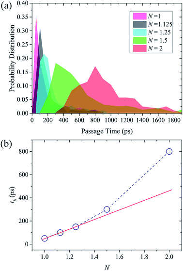
At last, the average time for a water molecule to permeate across the NSP is calculated to further demonstrate the nature of water flow through NSP. A passage time (t) is defined here as the time spent in the NSP, from crossing the lower graphene on the feed side to leaving the graphene on the permeate reservoir. According to the probability distribution of water passage time in Fig. 8(a), only one peak is observed in all cases. When N is no larger than 1.25, the passage time concentrated in a very narrow time range, meaning that the water molecules are rapidly transported across the NSP and water behavior tends to be regular. When N is increased to 1.5 and 2, the ordered water motion is greatly undermined and passage time is prolonged to a wide time range. As illustrated in Fig. 8(b), passage time with the highest probability (th) increases linearly with N when N is no larger than 1.25, but significantly increased when N is 1.5 and 2. The nonlinear raise of passage time in the latter case can be attributed to the water molecules' energetically unfavorable cracking from stable water layer in the pseudo-continuous transport mode. To summary, confinement resistance and the pitch-dependent transport mode jointly determine the water permeation, but the influence of transport mode is more prominent especially for NSP with narrow screw pitch.
4. Conclusions
It is demonstrated that NSP with tunable screw pitch can provide an effective means of water desalination. For NSP, confinement is created by decreasing screw pitch instead of screw diameter. As a result, perfect salt rejection can still be maintained with the increase of screw diameter. The larger the diameter, the more rapid water flux is obtained. Pitch-dependent water transport modes play more crucial roles than confinement resistance in determining water permeation through NSP. The concept of effective confinement is proposed to characterize the optimal confinement which can not only hinder the ion passage but exert least hindrance for water transport. Based to above mechanism, water permeation is further improved without compromising the ion rejection by decreasing the screw pitch number. With this strategy, on one hand, extra resistance exerted on the water flow by invalid confinement is removed and water velocity is significantly increased; on the other hand, the water molecules can also get rid of the unfavorable pseudo-continuous water transport mode, which helps to improve the water permeation indirectly. The salt rejection capacity and superior water permeation has proved the NSP an excellent nanodevice for not only water desalination, but also more general liquid separation based on space confinement.Conflict of interest
The authors declare no competing financial interest.Acknowledgements
This work was supported by the National Natural Science Foundation of China (11572307, 11525211 and 11472263), the Strategic Priority Research Program of the Chinese Academy of Sciences (XDB22040402). The numerical calculations have been done on the supercomputing system in the Supercomputing Center of University of Science and Technology of China.References
- M. A. Shannon, P. W. Bohn, M. Elimelech, J. G. Georgiadis, B. J. Marinas and A. M. Mayes, Nature, 2008, 452, 301–310 CrossRef CAS PubMed.
- M. Elimelech and W. A. Phillip, Science, 2011, 333, 712–717 CrossRef CAS PubMed.
- R. F. Service, Science, 2006, 313, 1088–1090 CrossRef CAS PubMed.
- Y. Zhu, Y. Ruan, Y. Zhang, L. Lu and X. Lu, Mol. Simul., 2016, 42, 784–798 CrossRef CAS.
- A. D. Khawaji, I. K. Kutubkhanah and J.-M. Wie, Desalination, 2008, 221, 47–69 CrossRef CAS.
- B. Corry, J. Phys. Chem. B, 2008, 112, 1427–1434 CrossRef CAS PubMed.
- B. Corry, Energy Environ. Sci., 2011, 4, 751–759 CAS.
- D. Cohen-Tanugi and J. C. Grossman, Nano Lett., 2012, 12, 3602–3608 CrossRef CAS PubMed.
- D. Cohen-Tanugi, L.-C. Lin and J. C. Grossman, Nano Lett., 2016, 16, 1027–1033 CrossRef CAS PubMed.
- L. F. Greenlee, D. F. Lawler, B. D. Freeman, B. Marrot and P. Moulin, Water Res., 2009, 43, 2317–2348 CrossRef CAS PubMed.
- C. Fritzmann, J. Löwenberg, T. Wintgens and T. Melin, Desalination, 2007, 216, 1–76 CrossRef CAS.
- L. Malaeb and G. M. Ayoub, Desalination, 2011, 267, 1–8 CrossRef CAS.
- K. P. Lee, T. C. Arnot and D. Mattia, J. Membr. Sci., 2011, 370, 1–22 CrossRef CAS.
- T. Humplik, J. Lee, S. O'hern, B. Fellman, M. Baig, S. Hassan, M. Atieh, F. Rahman, T. Laoui and R. Karnik, Nanotechnology, 2011, 22, 292001 CrossRef CAS PubMed.
- J. Kou, X. Zhou, H. Lu, F. Wu and J. Fan, Nanoscale, 2014, 6, 1865–1870 RSC.
- M. M. Pendergast and E. M. Hoek, Energy Environ. Sci., 2011, 4, 1946–1971 CAS.
- J. Kou, J. Yao, L. Wu, X. Zhou, H. Lu, F. Wu and J. Fan, Phys. Chem. Chem. Phys., 2016, 18, 22210–22216 RSC.
- Z. Hu, Y. Chen and J. Jiang, J. Chem. Phys., 2011, 134, 134705 CrossRef PubMed.
- R. Nair, H. Wu, P. Jayaram, I. Grigorieva and A. Geim, Science, 2012, 335, 442–444 CrossRef CAS PubMed.
- P. Goh and A. Ismail, Desalination, 2015, 356, 115–128 CrossRef CAS.
- C. Sun, B. Wen and B. Bai, Sci. Bull., 2015, 60, 1807–1823 CrossRef CAS.
- R. Joshi, P. Carbone, F. C. Wang, V. G. Kravets, Y. Su, I. V. Grigorieva, H. A. Wu, A. K. Geim and R. R. Nair, Science, 2014, 343, 752–754 CrossRef CAS PubMed.
- M. Hu and B. Mi, Environ. Sci. Technol., 2013, 47, 3715–3723 CrossRef CAS PubMed.
- K. Huang, G. Liu, Y. Lou, Z. Dong, J. Shen and W. Jin, Angew. Chem., Int. Ed., 2014, 53, 6929–6932 CrossRef CAS PubMed.
- L. Huang, M. Zhang, C. Li and G. Shi, J. Phys. Chem. Lett., 2015, 6, 2806–2815 CrossRef CAS PubMed.
- F. Perreault, A. F. de Faria and M. Elimelech, Chem. Soc. Rev., 2015, 44, 5861–5896 RSC.
- H. Y. Yang, Z. J. Han, S. F. Yu, K. L. Pey, K. Ostrikov and R. Karnik, Nat. Commun., 2013, 4, 2220 Search PubMed.
- S. Kar, R. Bindal and P. Tewari, Nano Today, 2012, 7, 385–389 CrossRef CAS.
- R. Das, M. E. Ali, S. B. A. Hamid, S. Ramakrishna and Z. Z. Chowdhury, Desalination, 2014, 336, 97–109 CrossRef CAS.
- A. Kalra, S. Garde and G. Hummer, Proc. Natl. Acad. Sci. U. S. A., 2003, 100, 10175–10180 CrossRef CAS PubMed.
- X. Gong, J. Li, H. Lu, R. Wan, J. Li, J. Hu and H. Fang, Nat. Nanotechnol., 2007, 2, 709–712 CrossRef CAS PubMed.
- J. Li, X. Gong, H. Lu, D. Li, H. Fang and R. Zhou, Proc. Natl. Acad. Sci. U. S. A., 2007, 104, 3687–3692 CrossRef CAS PubMed.
- G. Hummer, J. C. Rasaiah and J. P. Noworyta, Nature, 2001, 414, 188–190 CrossRef CAS PubMed.
- P. S. Goh, A. F. Ismail and B. C. Ng, Desalination, 2013, 308, 2–14 CrossRef CAS.
- Q. Tu, Q. Yang, H. Wang and S. Li, Sci. Rep., 2016, 6, 26183 CrossRef CAS PubMed.
- A. T. Nasrabadi and M. Foroutan, Desalination, 2011, 277, 236–243 CrossRef CAS.
- L. Y. Wang, H. A. Wu and F. C. Wang, Sci. Rep., 2017, 7, 41717 CrossRef CAS PubMed.
- J. Li, S. Sattayasamitsathit, R. Dong, W. Gao, R. Tam, X. Feng, S. Ai and J. Wang, Nanoscale, 2014, 6, 9415–9420 RSC.
- S. Tottori, L. Zhang, F. Qiu, K. K. Krawczyk, A. Franco-Obregón and B. J. Nelson, Adv. Mater., 2012, 24, 811–816 CrossRef CAS PubMed.
- L. Liu, S.-H. Yoo, S. A. Lee and S. Park, Nano Lett., 2011, 11, 3979–3982 CrossRef CAS PubMed.
- A. Ghosh and P. Fischer, Nano Lett., 2009, 9, 2243–2245 CrossRef CAS PubMed.
- H. Gao, X. Zhang, M. Zhou, E. Zhang and Z. Zhang, Solid State Commun., 2006, 140, 455–458 CrossRef CAS.
- H.-F. Zhang, C.-M. Wang, E. C. Buck and L.-S. Wang, Nano Lett., 2003, 3, 577–580 CrossRef CAS.
- H.-F. Zhang, C.-M. Wang and L.-S. Wang, Nano Lett., 2002, 2, 941–944 CrossRef CAS.
- M. Y. Yan, F. C. Wang, C. H. Han, X. Y. Ma, X. Xu, Q. Y. An, L. Xu, C. J. Niu, Y. L. Zhao and X. C. Tian, J. Am. Chem. Soc., 2013, 135, 18176–18182 CrossRef CAS PubMed.
- S. Manzetti, Adv. Manuf., 2013, 1, 198–210 CrossRef.
- L. Zhang, J. J. Abbott, L. Dong, B. E. Kratochvil, D. Bell and B. J. Nelson, Appl. Phys. Lett., 2009, 94, 064107 CrossRef.
- P. Fischer and A. Ghosh, Nanoscale, 2011, 3, 557–563 RSC.
- T. R. Kelly, H. De Silva and R. A. Silva, Nature, 1999, 401, 150–152 CrossRef CAS PubMed.
- N. Koumura, R. W. Zijlstra, R. A. van Delden, N. Harada and B. L. Feringa, Nature, 1999, 401, 152–155 CrossRef CAS PubMed.
- P. Král and H. Sadeghpour, Phys. Rev. B: Condens. Matter Mater. Phys., 2002, 65, 161401 CrossRef.
- P. Král and T. Seideman, J. Chem. Phys., 2005, 123, 184702 CrossRef PubMed.
- J. L. Abascal and C. Vega, J. Chem. Phys., 2005, 123, 234505 CrossRef CAS PubMed.
- C. L. Kong, J. Chem. Phys., 1973, 59, 2464–2467 CrossRef CAS.
- R. W. Hockney and J. W. Eastwood, Computer simulation using particles, CRC Press, 1988 Search PubMed.
- S. Plimpton, J. Comput. Phys., 1995, 117, 1–19 CrossRef CAS.
- W. Humphrey, A. Dalke and K. Schulten, J. Mol. Graphics, 1996, 14, 33–38 CrossRef CAS PubMed.
- J. W. Feng, H. M. Ding, C. L. Ren and Y. Q. Ma, Nanoscale, 2014, 6, 13606–13612 RSC.
- Q. Shao, J. Zhou, L. Lu, X. Lu, Y. Zhu and S. Jiang, Nano Lett., 2009, 9, 989–994 CrossRef CAS PubMed.
- X. Gong, J. Li, K. Xu, J. Wang and H. Yang, J. Am. Chem. Soc., 2010, 132, 1873–1877 CrossRef CAS PubMed.
- J. Zhang, M. K. Borg, K. Ritos and J. M. Reese, Langmuir, 2016, 32, 1542–1549 CrossRef CAS PubMed.
- J. Zhang, M. K. Borg, K. Sefiane and J. M. Reese, Phys. Rev. E, 2015, 92, 052403 CrossRef PubMed.
- Q. Shao, L. Huang, J. Zhou, L. Lu, L. Zhang, X. Lu, S. Jiang, K. E. Gubbins and W. Shen, Phys. Chem. Chem. Phys., 2008, 10, 1896–1906 RSC.
- S. C. O'Hern, M. S. Boutilier, J.-C. Idrobo, Y. Song, J. Kong, T. Laoui, M. Atieh and R. Karnik, Nano Lett., 2014, 14, 1234–1241 CrossRef PubMed.
| This journal is © The Royal Society of Chemistry 2017 |

