DOI:
10.1039/C7RA00998D
(Paper)
RSC Adv., 2017,
7, 14302-14308
Surface strengthening of injection molded parts by applying a thermal insulation film
Received
23rd January 2017
, Accepted 24th February 2017
First published on 3rd March 2017
Abstract
The main objective of this study is to strengthen the surface of injection molded parts by building up the compressive residual stress at the surface of the product. For this, we introduced a mold system for manipulating the heat transfer between the mold and the molten polymer with use of a thermal insulation film. The injection molding process was simulated, and the residual stress was obtained numerically. Experimental analysis of residual stress was also carried out using the hole drilling method. In addition, the scratch resistance and mechanical characteristics of the products were evaluated. The results indicated that the compressive residual stress was built up by employing the film and led to significant enhancement of the scratch resistance and mechanical properties of the molded parts.
1. Introduction
Injection molded plastic parts have become increasingly important for a wide range of applications such as electronics, automotive, medical, energy, and biological areas.1–4 They have shown very high versatility and extensibility due to their low cost, easy processability, high precision, and good surface finish.5–7 In spite of these advantages, the polymeric parts have a relatively short service life in products arising from their poor thermal and mechanical properties.8–10 For instance, continuous surface rubbing leads to the loss of optical and tribological performance of plastic parts. Indeed, there is a strong need to improve scratch resistance and impact strength of plastics, and especially for display applications that demand high surface quality and durability. In the last two decades, much effort has been made to examine the scratch behavior of polymeric parts.11–17 In general, the behavior has been understood from two points of view: one is to figure out characteristics related to the surface properties and the other is to comprehend the underlying physics of the corresponding features.
Residual stress, an internal stress of injection molded parts in the absence of external stress, is one of the main problematic issues determining the quality of products. As a result of the existence of residual stress, viscoelastic deformation, warpage, shrinkage, and even cracking can be induced in products. The residual stress developed in the injection molded parts are generated by three kinds of stresses including packing stress, flow-induced stress, and thermally-induced stress. First, the high packing pressure applied during compression stage yields the packing stress, which affects the shrinkage of parts.18,19 Second, the flow-induced residual stress originates from shear and/or extensional flows during filling stage. It leads to anisotropy of physical properties due to the molecular orientations along the parallel and perpendicular directions to the flow. Last, the thermal residual stress stems from the nonuniform phase change and solidification during cooling stage.20 Magnitude of the thermal residual stress changes depending on molding conditions, in particular, the heat transfer across the mold.21 Since complex residual stresses are developed in the injection molded parts, it is a challenging task to look into them in a precise and systematic manner.
The scratch resistance of a polymeric part, which is one of the most important surface properties, is determined by not only intrinsic material properties but also processing conditions. In particular, controlling the operation conditions is an easy, practical way for maximizing the scratch resistance by adjusting the phase change of polymer during cooling. The history of temperature for polymeric parts acts as a key factor of determining mechanical characteristics of products, such as modulus, hardness, surface strength, and scratch resistance.
For producing tough and durable plastic parts, a facile, applicable method of adjusting the cooling rate of polymer in the mold cavity is needed. From this point of view, we introduce a mold system that can control the heat transfer between the mold and the molten polymer adopting thermal insulation film. The surface properties of injection molded parts are significantly enhanced by generating compressive residual stress rather than tensile residual stress at the surface of the parts.
2. Experimental
2.1. Film lamination
In order to control the thermal energy transport through the mold wall during injection molding, a heat insulation layer on the mold wall was proposed by using polyimide (PI) film with a 100 μ thickness. We employed a laminating process joining a few prefabricated sheets of material. The lamination was performed using a roll. The film was a one-sided adhesive PI tape (Kora Taconic Co., Heat-resistant Masking Tapes, 6325-02H2) with excellent thermal resistance, solvent resistance and adhesion strength. As listed in Table 1 (Korea Taconic Co.), the PI film possesses appropriate thermal properties for the heat insulation. Thickness of the film was determined considering several factors such as optimization of thermal insulation and cooling time, and durability of the film.
Table 1 Thermal properties of the PI film
| Thermal property |
Typical value |
Test condition |
Test method |
| Melting point |
None |
None |
ASTM E-794-85 |
| Thermal coefficient of linear expansion |
20 ppm per °C, (11 ppm per °F) |
−14 to 38 °C, (7 to 100 °F) |
ASTM D-696-91 |
| Coefficient of thermal conductivity, W m−1 K−1 (cal cm−1 sec−1 °C−1) |
0.12, (2.87 × 10⁻⁴) |
296 K, (23 °C) |
ASTM F-433-77 |
| Specific heat, J g−1 K−1 (cal g−1 °C−1) |
1.09 (0.261) |
|
Differential calorimetry |
| Shrinkage, % |
0.17 |
30 min at 150 °C |
IPC TM 650, method 2.2.4A ASTM D-5214-91 |
| 1.25 |
120 min at 400 °C |
2.2. Injection molding
Two different cores of mold were used in this research: one is the PI film laminated core, and the other is without the film lamination as a control. COC (cyclic olefin copolymer, TOPAS advanced polymers Co.) was employed for injection molding. It consisted of pellets with a diameter of around 1 mm. Prior to injection molding, the resin was completely dried using a dehumidifier (Purpose VHM5-LC, HANSE cop) at 70 °C for 5 hours in vacuum environment. The temperature of melting cylinder to nozzle in the injection molding machine was set from 305 °C to 330 °C in a successive fashion. The mold temperature distribution over the mold surface was controlled using the cooling line of mold. The mold was pre-warmed for 3 hours to secure enough time for thermal equilibrium.
2.3. Hole-drilling method
There are two types of measurement techniques for the residual stress, destructive method and non-destructive method.20 The former encompasses layer removal, hole drilling, and chemical probe methods, and the latter does photoelastic technique, X-ray technique, and holographic interferometry. Among these, the hole-drilling method is a more flexible and applicable technique than the others in that it is capable of determining the residual stress profiles with respect to depth at different positions in injection molded parts.22 In order to obtain a representative profile for residual stress in the thickness direction, the test was carried out at the center of samples. A strain gauge rosette was fixed on the surface of injection molded parts using cyanoacrylate adhesive. A drill was positioned at the center of the rosette using an optical microscope. Holes were drilled in depth increments of 0.1 mm with a radius of 0.94 mm. At each depth, about 3 min was given to stabilize the samples prior to the measurements. The residual stresses in the specimen were then calculated at each hole depth using the results of strain gauge. The residual stresses are expressed as below:| |
 | (1) |
where A = −a(1 − ν)/2E, B = −b/2E, σ is the maximum principal stress at the hole location. Here, ε1, ε2, and ε3 are the relieved strains measured from radially orientated strain gauges. For more details, ε1 and ε3 are the values along the two principal axes perpendicular to each other, and ε2 is the value at 45° to the two principal axes. E and ν are the modulus and Poisson's ratio of the injection molded part, respectively, and a and b are dimensionless calibration coefficients.
2.4. Scratch test
The scratch test was performed with the use of the universal macro & micro mechanical and tribological tester with a thermocamera, UMT-2M (Bruker-CETR). A diamond indenter was pressed onto the flat molded surface of each sample until a complete load-indentation depth curve was achieved. Tangential force, Fx and normal force, Fz were continuously measured during the scratch process. In the experiment, a cone-typed Rockwell Diamond indenter was employed with a velocity of 1 mm s−1.
2.5. Nanoindentation test
Nanoindentation experiments were performed using a high temperature ultra-nanoindentation tester (UltraNano, CSM). The Berkovich tip was used, and a quasi-static load function with a peak force of 500 μN was applied. At least 4 tests were repeated and averaged.
3. Numerical simulation
3.1. Injection molding analysis
We simulated numerically the whole processes of injection molding to figure out the effect of thermal insulation film on the residual stress of injection molded parts. The governing equations for filling the mold cavity are the continuity, the momentum and the energy equations as follows:1| |
 | (2) |
| |
 | (3) |
| |
 | (4) |
where ρ is the density, ṽ is the velocity vector, P is the pressure, ![[small tau, Greek, tilde]](https://www.rsc.org/images/entities/i_char_e0e5.gif) is the viscous stress tensor,
is the viscous stress tensor, ![[g with combining tilde]](https://www.rsc.org/images/entities/i_char_0067_0303.gif) is the gravity/body-force vector, Cp is the specific heat at constant pressure, β is the coefficient of thermal expansion, η is the so-called generalized Newtonian viscosity, and
is the gravity/body-force vector, Cp is the specific heat at constant pressure, β is the coefficient of thermal expansion, η is the so-called generalized Newtonian viscosity, and ![[q with combining tilde]](https://www.rsc.org/images/entities/i_char_0071_0303.gif) is the heat flux. Here,
is the heat flux. Here, ![[small gamma, Greek, dot above]](https://www.rsc.org/images/entities/i_char_e0a2.gif) is the shear rate,
is the shear rate,| |
 | (5) |
where (u, v) are the velocity component in the (x, y) directions. The flow front in the cavity is tracked using a fluid concentration equation, which can be expressed as| |
 | (6) |
where F is the fluid concentration. Since the polymer melt was regarded as a non-Newtonian viscous fluid in this study, the following modified Cross model was adopted for the fluid.| |
 | (7) |
where η is the viscosity, η0 is the zero shear rate viscosity, τ* is the shear stress at the transition between the Newtonian and the Power law behavior and n is the Power law index. η0 can be represented as a function of temperature using the Williams–Landel–Ferry (WLF) equation:| |
 | (8) |
where T*(P) = D2 + D3P. The material constants for eqn (7) and (8) and COC are listed in Table 2, which are obtained from Moldex3D.
Table 2 Material constants of the COC polymer
| N |
τ* (kPa) |
D1 (GPa) |
D2 (K) |
D3 (K Pa−1) |
A1 |
A2 |
| 0.428 |
36.632 |
9.46 × 10⁴ |
343.15 |
0 |
42.775 |
51.6 |
4. Results and discussion
Fig. 1(a) demonstrates how a compressive residual stress at the surface of a molded part resists an external force applied to the part. On the contrary, if there exists a tensile residual stress at the surface, it can cause crack or plastic deformation (e.g., scratch) as explained in Fig. 1(b). Generally, the tensile residual stress is built up in the injection molded parts. For hardening the surface of parts, forging a metal is one example where a compressive force is imposed to the surface of metallic products. Another example of hardening materials is the ion exchange method, which applies compressive stress to the surface of typically glass materials. The compressive stress is created by the so-called “stuffing” or “crowding” effect due to the replacement of small alkali ions with large ions. The molten polymer in the filling stage of injection molding experiences extremely fast solidification on the mold surface by thermal shock, which occurs due to a large temperature distinction between the mold surface and the molten polymer and a high thermal conductivity of metal mold. As a result, the skin layer is formed as soon as a molten polymer is injected in the mold cavity. In general, the friction and constraint of mold wall and the molecular orientation of polymers result in the generation of tensile stress in the skin layer. Fig. 2 shows the snapshots of the mold used and the film laminated on the mold core. In the current study, a light guide plate was designed and fabricated using injection molding. Since the plate is thin, it is critical to precisely control the heat transfer during filling and cooling steps of injection molding. Since the PI film used in this study has a very low thermal conductivity (i.e., 0.12 W m−1 K−1) at the mold wall compared with that of the mold metal, the film can highly contribute to the overall thermal conductivity at the mold wall. By adopting the insulation film, we can reduce the overall thermal conductivity at the wall efficiently and control the heat transfer between molten polymer and mold during processing in an active manner.
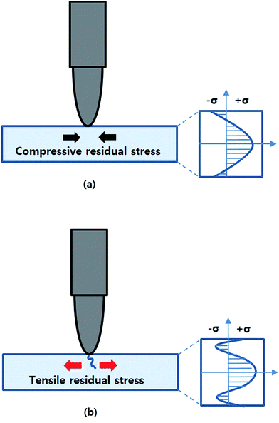 |
| | Fig. 1 Schematic diagrams of the scratch test for injection molded parts: (a) compressive residual stresses in the skin layer and (b) tensile residual stresses in the skin layer. | |
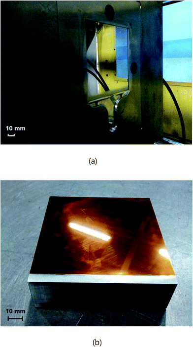 |
| | Fig. 2 (a) Image of the mold used in this study and (b) image of the film laminated on the mold core. | |
Fig. 3 presents the numerical results of residual stress distribution in the light guide plate prepared using typical injection molding, that is, without thermal insulation film. It is known that injection molded parts are likely to have tensile residual stresses in the product surface due to the frictional force on the mold wall, as shown in the figure. Fig. 3(a) and (b) show the residual stress distributions in x-direction (i.e., flow direction) and y-direction (i.e., transfer direction), respectively. It is found that tensile residual stresses of approximately 1 to 3 MPa are built up in the surface area except for the edge of part. Our previous studies suggest that the residual stress of molded products in the gapwise direction is developed as the distribution demonstrated in Fig. 1(b).23,24
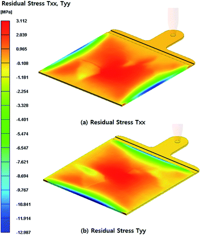 |
| | Fig. 3 Residual stress distributions in the light guide plate calculated without considering the thermal insulation film: (a) flow direction and (b) transverse direction. | |
Fig. 4 exhibits the numerical results of residual stress distribution in the wave in the light guide plate prepared using the thermal insulation film. Unlike the results of Fig. 3, the compressive residual stresses were found to exist in the product surface. This numerical result was verified by the hole drilling method. On the other hand, it is not easy to obtain reliable quantitative data of the gapwise residual stress profile for injection molded products. As aforementioned, the hole drilling method was adopted to secure the residual stress distribution with respect to thickness in this study. Fig. 5 shows experimental results of the residual stress profiles as a function of the hole depth. For the test, the minimum hole drilling step was 0.1 mm. When the specimen was injection-molded without the thermal insulation, the tensile residual stress was found in the skin and core regions of the part and the compressive residual stress was developed in the shear layer beneath the skin layer of the specimen. This result supports the numerical result showing the existence of the tensile residual stress in the product surface. However, when the thermal insulation film was adopted in the processing, the compressive residual stress was identified experimentally (Fig. 5(b)). This residual stress profile was similar to that presented in Fig. 1(a). The generated compressive stress in the surface region leads to a significant enhancement in the surface properties.
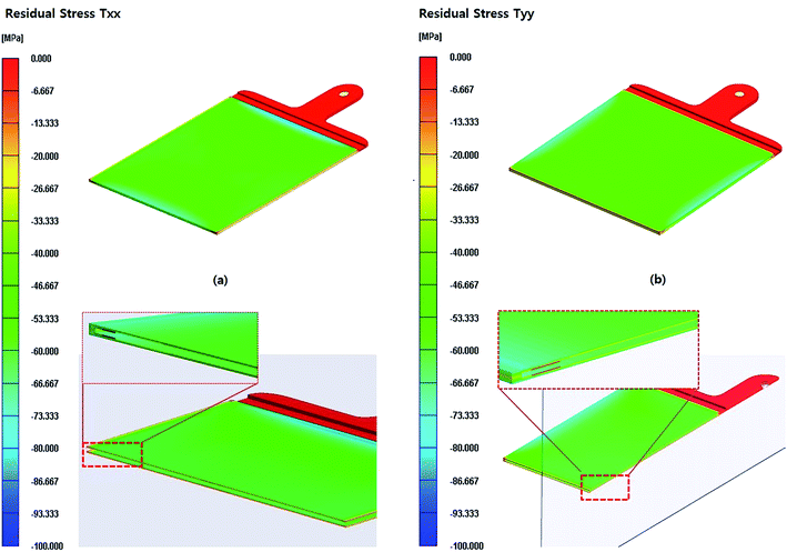 |
| | Fig. 4 Residual stress distributions in the light guide plate calculated considering the thermal insulation film: (a) flow direction and (b) transverse direction. | |
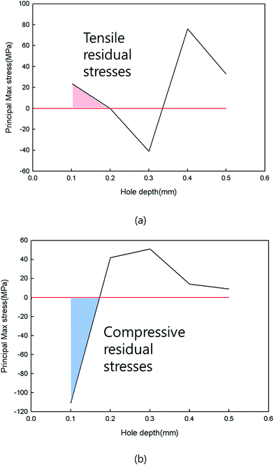 |
| | Fig. 5 Residual stress profiles in the gapwise direction of injection molded parts: (a) without the thermal insulation film and (b) with the thermal insulation films on the mold surface. | |
Scratch resistance can be determined from forces necessary to penetrate the surface of material with an indenter and to drag the indenter. Fig. 6(a) shows the image of the scratch damage and the variation of normal and tangential forces to applied to injection molded specimens with respect to the displacement. Both normal and tangential forces increased with an increase in the penetration depth. In comparison with the results of Fig. 6(b), the sample fabricated using the thermal insulation film showed relatively small damage area and large normal and tangential forces, which could be explained by the presence of compressive residual stress of the product. For instance, the normal forces for penetrating the sample surfaces prepared with and without the film were 23 N and 7.5 N, respectively.
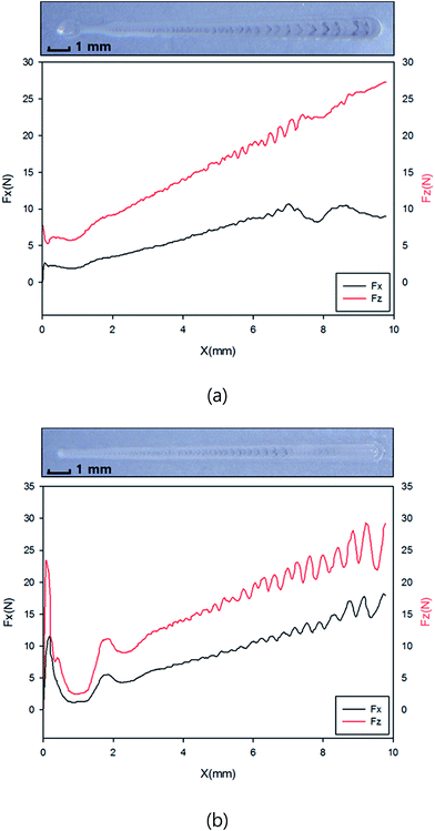 |
| | Fig. 6 Profilometer results of the scratch damage and the variation of normal and tangential forces as a function of the displacement: (a) without the thermal insulation film and (b) with the thermal insulation film on the mold surface. | |
Fig. 7 presents the force–displacement curves obtained from the nanoindentation tests. From Fig. 7(a), the average modulus and hardness of the sample produced without the thermal insulation film were found to be 5.5 GPa and 0.33 GPa, respectively. On the other hand, Fig. 7(b) revealed that the average modulus and hardness of the other sample were 6.6 GPa and 0.46 GPa, respectively. Similar to the result of the scratch test, the nanoindentation result showed the positive effect of the compressive residual stress in the injection molded parts. Overall, we foresee that this study could help develop a facile and effective method of controlling the cooling rate of molten polymer in the mold cavity and understand the underlying physics of the generation mechanism and resulting effect of the compressive residual stress.
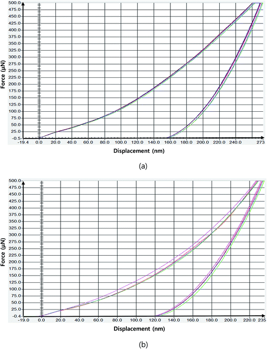 |
| | Fig. 7 Plot of the force against the displacement obtained from the nanoindentation tests: (a) without the thermal insulation film and (b) with the thermal insulation film on the mold surface. | |
5. Conclusions
This research illustrated that the surface of injection molded parts was significantly strengthened by the compressive residual stress in the surface region of the product. The residual stress distribution of polymeric products can be manipulated by controlling the heat transfer between molten polymer and mold during processing. The focus of this study was mainly on how to adjust the thermally induced residual stress in an active way rather than the flow induced residual stress in the molded parts. To provide in-depth understanding the formation mechanism and relevant physics of residual stress, we carried out numerical simulation regarding the injection molding process using the thermal insulation system. Experimental analysis of residual stress was conducted with use of the hole drilling method. In addition, the scratch resistance and nanoindentation tests were performed to look into the effect of the compressive residual stress generated with help of the thermal insulation film on the mold wall. The findings showed that the compressive residual stress caused significant improvement of scratch resistance and mechanical properties of molded parts, such as modulus and hardness. We anticipate that this facile and effective method of controlling the heat transfer by the thermal insulation film could be widely employed in the polymer processing areas in a bid to enhance the quality of polymeric products.
Acknowledgements
This work was supported by the Commercializations Promotion Agency for R&D Outcomes (COMPA) funded by the Ministry of Science, ICT and Future Panning (MISP). In addition, it was supported by the Industrial Strategic Technology Development Program funded by the Ministry of Trade, Industry and Energy (MI, Korea) [10052641].
References
- H. J. Oh and Y. S. Song, RSC Adv., 2015, 5, 99797–99805 RSC.
- M. R. Kamal, R. A. Lai-Fook and J. R. Hernandez-Aguilar, Polym. Eng. Sci., 2002, 42, 1098–1114 CAS.
- L. Yu, C. G. Koh, L. J. Lee, K. W. Koelling and M. J. Madou, Polym. Eng. Sci., 2002, 42, 871–888 CAS.
- A. I. Isayev, G. D. Shyu and C. T. Li, J. Polym. Sci., Part B: Polym. Phys., 2006, 44, 622–639 CrossRef CAS.
- C. Weng, W. B. Lee and S. To, Polym. Test., 2009, 28, 709–714 CrossRef CAS.
- H. L. Chen, S. C. Chen, W. H. Liao, R. D. Chien and Y. T. Lin, Int. Commun. Heat Mass Transfer, 2013, 41, 34–40 CrossRef.
- S. C. Nian, C. Y. Wu and M. S. Huang, Int. Commun. Heat Mass Transfer, 2015, 61, 102–110 CrossRef.
- D. Teixeira, M. Giovanela, L. B. Gonella and J. S. Crespo, Mater. Des., 2015, 85, 695–706 CrossRef CAS.
- C. Xiang, H. J. Sue, J. Chu and B. Coleman, J. Polym. Sci., Part B: Polym. Phys., 2001, 39, 47–59 CrossRef CAS.
- M. Wong, A. Moyse, F. Lee and H. J. Sue, J. Mater. Sci., 2004, 39, 3293–3308 CrossRef CAS.
- ASTM International, ASTM D7027-05, 2005.
- M. H. Blees, G. B. Winkelman, A. R. Balkenende and J. M. J. den Toonder, Thin Solid Films, 2000, 359, 1–13 CrossRef CAS.
- B. J. Briscoe, A. Delfino and E. Pelillo, Wear, 1999, 225–229, 319–328 CrossRef CAS.
- J. Chu, C. Xiang, H. J. Sue and R. D. Hollis, Polym. Eng. Sci., 2000, 40, 944–955 CAS.
- R. S. Hadala and R. D. K. Misraa, Mater. Sci. Eng., A, 2005, 398, 252–261 CrossRef.
- H. Jiang, G. T. Lim, J. N. Reddy, J. D. Whitcomb and H. J. Sue, J. Polym. Sci., Part B: Polym. Phys., 2007, 45, 1435–1447 CrossRef CAS.
- B. Ozcelik and I. Sonat, Mater. Des., 2009, 30, 367–375 CrossRef CAS.
- M. Wong, G. T. Lim, A. Moyse, J. N. Reddy and H. J. Sue, Wear, 2004, 256, 1214–1227 CrossRef CAS.
- J. A. Williams, Tribol. Int., 1999, 29, 675–694 CrossRef.
- A. Guevara-Morales and U. Figueroa-López, J. Mater. Sci., 2014, 49, 4399–4415 CrossRef CAS.
- K. K. Kabanemi, H. Vaillancourt, H. Wang and G. Salloum, Polym. Eng. Sci., 1998, 38, 21–37 CAS.
- S. Y. Pak, S. Y. Kim, S. H. Kim and J. R. Youn, Polym. Test., 2013, 32, 946–952 CrossRef CAS.
- H. J. Oh, D. J. Lee, C. G. Lee, K. Y. Jo, D. H. Lee, Y. S. Song and J. R. Youn, Composites, Part A, 2013, 53, 34–45 CrossRef CAS.
- H. J. Oh, Y. S. Song, S. H. Kim, S. Y. Kim and J. R. Youn, Polym. Eng. Sci., 2011, 51, 812–818 CAS.
|
| This journal is © The Royal Society of Chemistry 2017 |
Click here to see how this site uses Cookies. View our privacy policy here.  Open Access Article
 *b
*b


![[small tau, Greek, tilde]](https://www.rsc.org/images/entities/i_char_e0e5.gif) is the viscous stress tensor,
is the viscous stress tensor, ![[g with combining tilde]](https://www.rsc.org/images/entities/i_char_0067_0303.gif) is the gravity/body-force vector, Cp is the specific heat at constant pressure, β is the coefficient of thermal expansion, η is the so-called generalized Newtonian viscosity, and
is the gravity/body-force vector, Cp is the specific heat at constant pressure, β is the coefficient of thermal expansion, η is the so-called generalized Newtonian viscosity, and ![[q with combining tilde]](https://www.rsc.org/images/entities/i_char_0071_0303.gif) is the heat flux. Here,
is the heat flux. Here, ![[small gamma, Greek, dot above]](https://www.rsc.org/images/entities/i_char_e0a2.gif) is the shear rate,
is the shear rate,


