 Open Access Article
Creative Commons Attribution 3.0 Unported Licence
Retracted Article: Synthesis and application of monodisperse hydrophobic magnetite nanoparticles as an oil spill collector using an ionic liquid†
Ayman M. Atta *ab,
Abdelrhman O. Ezzata and
Ahmed I. Hashemc
aChemistry Department, College of Science, King Saud University, Riyadh 11451, Saudi Arabia. E-mail: aatta@ksu.edu.sa
bPetroleum Application Department, Egyptian Petroleum Research Institute, Nasr City 11727, Cairo, Egypt
cChemistry Department, Faculty of Science, Ain Shams University, Abasia, 11566 Cairo, Egypt
First published on 15th March 2017
Abstract
In this work, a new facile green method was proposed to prepare monodisperse magnetic nanoparticles at room temperature with controlled shape and size. In this respect, a new ionic liquid based on 1-allyl-3-methylimidazolium oleate (AMO) was prepared and applied as a capping and stabilizing agent for magnetite at low temperature. The chemical structure, morphology, particle size, crystal structure and monodispersity of magnetite capped with AMO were determined. The magnetic properties and porosity of the prepared magnetite nanomaterials were evaluated using different analytical techniques. The efficiency of the prepared magnetite nanomaterials as an oil spill collector confirmed their high selectivity and oil collection efficiency on the surface of seawater using a low concentration of nanomaterials in relation to the size of the crude oil spill.
1. Introduction
Petroleum crude oil spill disasters can occur during the production and transportation of crude oil and produce several environmental hazards, such as toxic organic water pollutants. Such disasters cost the world over billions of dollars due to the loss of valuable energy resources in the crude oil and the resources required to clean up the mess.1 The chemical treatment of oil spills has attracted great attention, among other mechanical methods and equipment to prevent the oil spill from spreading into a large area. There are different chemical methods that have been widely used to control oil spill pollution, involving the application of either natural or synthetic chemicals.2–5 The selection of chemicals to alleviate oil spill pollution is based on the dispersion, emulsification, demulsification, adsorption and collection mechanisms.6–8 Recently, the development of porous materials as oil spill adsorbents or collectors has attracted much attention because, in terms of initial cost, they are simple and easy to design for fast operation. Such materials are effective and can feasibly be reused, among other materials.9–13 It was also found that porous adsorbents possessing a balance of both superhydrophobicity and superoleophilicity are promising materials.10–16 More recently, the use of adsorbents with a combination of porosity and magnetic properties has been proposed as the most effective magnetic separation technique for applying nanocomposites for water treatment and oil spill collection.17–21 Hydrophobic magnetic nanomaterials have also been proposed to control water pollution from crude oil spills due to their excellent dispersion in crude oil and good response to an external magnetic field. Different methods have been used to prepare magnetic nanomaterials based on magnetite, such as co-precipitation, microemulsion, thermal decomposition, and hydrothermal synthesis.22–25 In all methods, the aim is to prepare highly dispersed magnetite without agglomeration by selecting the best capping agents, which help to increase the dispersion of magnetite, reduce the particle size and control the magnetic properties of the materials.Ionic liquids, ILs, have received a significant amount of interest for the production of magnetic nanomaterials with controlled shapes, dispersion and nanostructures.26–28 Moreover, ILs, as green chemicals, have been proposed to be alternative chemicals that can protect the environmental ecosystem from pollution, instead of other chemicals used to treat and clean-up oil spills.25 Magnetic nanomaterials, consisting of high-quality, monodisperse and crystalline magnetite with a narrow size distribution, have been prepared using high-temperature organic phase decomposition methods.29 More recently, ILs have been used to prepare high-quality, monodisperse inorganic nanomaterials at room temperature.30,31 It has also been reported that highly ordered ILs can be used to form nanometer-size clusters at room temperature.23,32 These ILs behave like a nanostructured liquid medium that has an intrinsic “nanostructure” that is produced by electrostatic, hydrogen bonding and van der Waals interactions.32 In this respect, magnetic nanoparticles can be anchored onto the ILs, which are based on 3-methylimidazolium, to combine the unique properties of both the magnetic nanomaterials and the ILs at elevated temperature.27–31 A literature survey indicated that uniform hydrophobic magnetic nanoparticles with excellent paramagnetic performance cannot be produced at low reaction temperature. In this work, a facile, green, one-step method was suggested to produce monodisperse hydrophobic magnetite nanoparticles capped with a new IL based on 1-allyl-3-imidazolium oleate at room temperature. The IL was used to efficiently tune the growth of the magnetite particles and prevent intraparticle aggregation. The application of the synthesized magnetic nanomaterials for collecting heavy petroleum crude oil from polluted water surfaces is another goal of the present work.
2. Experimental
2.1. Materials
All chemicals used in this work to prepare the hydrophobic ionic liquid and magnetite nanoparticles were purchased from Sigma-Aldrich Chemicals Co. and used without further purification. The reagents used to prepare the hydrophobic IL were 1-allyl-3-methylimidazolium chloride (AMC), potassium hydroxide (KOH), oleic acid (OA), methanol and ethanol. The reagents used to prepare the magnetite nanomaterials were based on ferric chloride hexahydrate (FeCl3·6H2O), potassium iodide (KI), and ammonium hydroxide (25%).Arabian heavy crude oil produced from the Ras Gara oil field, Ras Tannora, Saudi Arabia and seawater collected from the western Arabian Gulf at the Saudi coast were used to simulate an oil spill.
2.2. Preparation of magnetite capped with hydrophobic IL
AMC (3 g; 0.019 mol) dissolved in methanol (10 mL) was mixed with KOH (0.019 mol dissolved in 10 mL of methanol) under vigorous stirring to precipitate KCl. The solid precipitate was filtered off from the reaction mixture. OA (0.019 mol dissolved in 5 mL of methanol) was added to the reaction mixture under vigorous stirring at room temperature for 2 h. Methanol was removed from the reaction mixture at the end of the reaction time under reduced pressure to obtain a brownish yellow oil with a reaction yield of 99.5%. The obtained product was 1-allyl-3-methylimidazolium oleate, designated as AMO.FeCl3·6H2O (7.21 g dissolved in 50 mL of distilled water) was added to KI solution (3.3 g dissolved in 75 mL of distilled water) under stirring and nitrogen atmosphere for 1 h. The solid iodine precipitate was filtered off from the reaction mixture. The AMO (2 g dissolved in 100 mL of ethanol) was added to the reaction mixture filtrate at the same time as an ammonia solution (50 mL) during a period of 1 h. The black colloid reaction mixture was stirred for another 3 h under nitrogen atmosphere. The black precipitate was separated by ultracentrifugation of the solution at 12![[thin space (1/6-em)]](https://www.rsc.org/images/entities/char_2009.gif) 000 rpm, and washed with water and ethanol several times.
000 rpm, and washed with water and ethanol several times.
2.3. Characterization
All instruments used to characterize the prepared IL and magnetite nanoparticles are described in the ESI.†2.4. Application of magnetite AMO powder as a crude oil spill collector
Arabian heavy crude oil (1 mL) was spread over 250 mL of seawater. The magnetite powder was spread onto the surface of the oil and the oil was mixed with a glass rod to disperse the magnetite powder in the crude oil. Magnetite to oil ratios ranging from 1![[thin space (1/6-em)]](https://www.rsc.org/images/entities/char_2009.gif) :
:![[thin space (1/6-em)]](https://www.rsc.org/images/entities/char_2009.gif) 10 to 1
10 to 1![[thin space (1/6-em)]](https://www.rsc.org/images/entities/char_2009.gif) :
:![[thin space (1/6-em)]](https://www.rsc.org/images/entities/char_2009.gif) 50 were used to study the effect of the magnetite ratio on the oil spill collection efficiency. Slow stirring of the oil/powder mixture was continued for 1 minute. The dispersed crude oil spill was collected after 5 min using a permanent magnet of Nd–Fe–B (4300 Gauss). The remaining oil was extracted from the water surface using chloroform, which was then evaporated using a rotary evaporator under reduced pressure. The crude oil collection efficiency can be calculated as a percentage using the following equation: CE (%) = (volume of removed oil/volume of original spill) × 100.
50 were used to study the effect of the magnetite ratio on the oil spill collection efficiency. Slow stirring of the oil/powder mixture was continued for 1 minute. The dispersed crude oil spill was collected after 5 min using a permanent magnet of Nd–Fe–B (4300 Gauss). The remaining oil was extracted from the water surface using chloroform, which was then evaporated using a rotary evaporator under reduced pressure. The crude oil collection efficiency can be calculated as a percentage using the following equation: CE (%) = (volume of removed oil/volume of original spill) × 100.
The magnetite powders were reused after isolation by an external magnetic field after dilution of the crude oil/magnetite solution with chloroform.
3. Results and discussion
3.1. Characterization of AMO IL
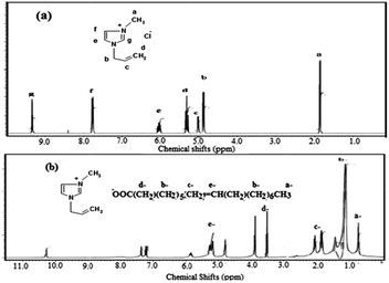
The present work aims to prepare a hydrophobic IL by replacing the chloride anion in AMC with an oleate group through reacting AMC with sodium hydroxide followed by reaction with oleic acid as represented in the Experimental section and Scheme 1.The chemical structure of the new ionic liquid, AMO, is elucidated from 1H NMR of AMC and AMO as represented in Fig. 1a and b. The protons of AMC are marked in Fig. 1a.32 The replacement of the chloride anion with an oleate anion is confirmed from the appearance of new peaks at chemical shifts of 0.7, 1.14, 2.5 and 5.2 ppm, which are attributed to CH3, (CH2)7, CH2COO and CH![[double bond, length as m-dash]](https://www.rsc.org/images/entities/char_e001.gif) CH of the oleate group, respectively. It was also found that the +N
CH of the oleate group, respectively. It was also found that the +N![[double bond, length as m-dash]](https://www.rsc.org/images/entities/char_e001.gif) CH protons were deshelled from 9.3 to 10.3 ppm due to the effect of the oleate carboxylate group.32
CH protons were deshelled from 9.3 to 10.3 ppm due to the effect of the oleate carboxylate group.32
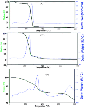
The thermal stability of AMO was confirmed using TGA and DTG analysis as represented in Fig. 2a–c. AMC loses approximately 7.3% of its weight after heating up to 100 °C. These data confirm that AMC is linked with water. The decomposition of AMO started at 240.3 °C and ended at around 317.4 °C with a weight loss of 84%, as shown in Fig. 2a. The fact that AMO didn't start to decompose until 255 °C, without any water loss, confirmed the low affinity of AMO for water due to the hydrophobicity of the oleate anion. The presence of long chain oleate hydrocarbons assisted the easy decomposition of AMO from 290 °C up to 650 °C without any remaining residue, due to the flexibility of the chains. These data indicate that the oleate group reduced the thermal stability of AMO in comparison to AMC.
The chain flexibility and thermal characteristics, such as crystallization and melting temperature, of AMC and AMO were determined from the DSC thermograms, as shown in the ESI (Fig. S1†). It was noticed that the replacement of the chloride anion in AMC with oleate converted AMC, which is solid at room temperature, to AMO, which is liquid at room temperature, due to the unsaturation of the OA group. The melting temperature, Tm, of an IL is an important indicator to confirm the purity of the IL. The data show only one transition from the highest position at the peak of the heating cycle at a Tm of 34 and 4 °C for AMC and AMO, respectively. The appearance of one Tm confirms the purity of both AMC and AMO as ILs. The existence of the crystallization temperature, Tc, of AMO at −54 °C and the absence of this peak in the DSC thermogram suggest that the presence of unsaturated OA increases the planarity of AMO due to the overlapping and interaction between the allyl group in the alkyl chain of the imidazolium ring and OA.33
3.2. Synthesis and characterization of magnetic nanoparticles capped with AMO
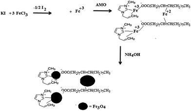
Magnetite nanoparticles (MNPs) have previously been prepared in the presence of different ILs based on N-alkyl imidazole using the co-precipitation method, but it was not possible to control their dispersity and aggregation, although their sizes and diameters could be modified.34–36 Moreover, monodisperse magnetite nanoparticles have only been prepared at high temperature through decomposition of organic precursors of iron salts.37–39 Alternatively, a microwave technique has been used as an alternative method to produce MNPs in the presence of an IL; monodisperse nanoparticles, with a particle size of 6 nm, were prepared from an organic precursor of an iron salt and 1,2-hexadecanediol in dibenzyl ether in the presence of oleic acid.40 The present work aimed to prepare superior MNPs using a new IL based on a co-precipitation method at low temperature as reported in the Experimental section. In our previous work, ferrous and ferric cations were produced from the oxidation reaction of ferric chloride with potassium iodide.21 The produced iron cations can be stabilized with the prepared AMO in an ethanol/water mixture as represented in Scheme 2.The iron cations can be stabilized by AMO through chelation with the oleate carboxylate anion and interaction with the unsaturated double bond and allyl bonds of oleate.41 The repulsion between the imidazolium cations of the prepared AMO and the iron cations facilitates the capping of the iron cations with the carboxylate anions of OA to control the dispersity, particle size and porosity. The proposed mechanism suggests that monodisperse Fe3O4 nanocrystals can be rapidly formed at low temperature, which can be observed using different characterization techniques.
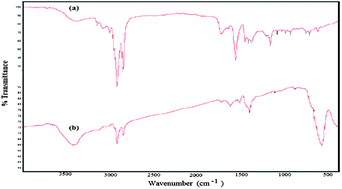
The formation of magnetite nanoparticles and the interaction between magnetite and AMO was confirmed using FTIR, as shown in Fig. 3a and b. The appearance of a strong and broad band at 579 cm−1, corresponding to the Fe–O vibration of the magnetic core, confirms the formation of magnetite without impurities of other iron oxides. The strong absorbance band at 3423 cm−1 is assigned to the formation of hydroxyl groups at the magnetite surface. The bands at 3049, 2980 and 2850 cm−1 were observed for both magnetite capped with AMO and AMO, resulting from the vibration of olefin and the paraffin CH stretching vibration of AMO. Moreover, the absorbance bands at wavenumbers of 1562 and 1458 cm−1 were assigned to the stretching vibration of the imidazole ring, which confirms that AMO is immobilized onto the surface of the magnetite. The lowering of the intensity of the band at 1729 cm−1, attributed to the vibration stretching of C![[double bond, length as m-dash]](https://www.rsc.org/images/entities/char_e001.gif) O of the oleate carboxylate anion, and increase in the intensity of the bands at 1630 cm−1 and 1549 cm−1, characteristic of asymmetric and symmetric COO– vibration, confirm the chelating bidentate interaction between oleic acid and Fe atoms on the surface of the particles when magnetite is capped with AMO (Fig. 3b). All these data show that the interaction of magnetite with the carboxylate anion of AMO protects the magnetite from oxidation to other iron oxides.42
O of the oleate carboxylate anion, and increase in the intensity of the bands at 1630 cm−1 and 1549 cm−1, characteristic of asymmetric and symmetric COO– vibration, confirm the chelating bidentate interaction between oleic acid and Fe atoms on the surface of the particles when magnetite is capped with AMO (Fig. 3b). All these data show that the interaction of magnetite with the carboxylate anion of AMO protects the magnetite from oxidation to other iron oxides.42
The purity of the magnetite nanoparticles capped with AMO without the formation of other iron oxides can be confirmed from XRD diffractograms, as shown in the ESI (Fig. S2†). It was found that six characteristic peaks appeared at 2-theta values of 30.5° (2 2 0), 35.9° (3 1 1), 43.5° (4 0 0), 53.9° (4 2 2), 57.3° (5 1 1) and 63.1° (440). These peaks show that the crystal structure of the Fe3O4 particles was not changed after modification with AMO, and matched well with the standard diffractions of Fe3O4 (JCPDS 89-4319). The appearance of the peaks as broad bands with a wide width and low intensity confirms the small particle size of the magnetite capped with AMO; the particle size calculated using Scherrer's equation from the (220), (311), and (400) planes was approximately 6.83 nm.
The content of magnetite incorporated with AMO can be determined from the TGA and DTG thermograms shown in Fig. 2c. The remaining residue after heating the solid at 750 °C in the presence of an oxygen atmosphere indicates that the contents of magnetite and AMO are 83 and 17 wt%, respectively. This result confirms that 17 wt% of AMO is sufficient to cap the magnetic nanoparticles.
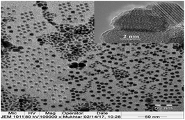
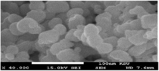
The surface morphology of the magnetite nanoparticles capped with AMO can be observed from the TEM and SEM micrographs shown in Fig. 4 and 5, respectively. The HR-TEM image shown in the inset of Fig. 4 shows that each individual Fe3O4 particle is single crystalline and ordered into atomic lattice fringes. The interfringe distances are measured to be 0.421 and 0.461 nm, which is close to the lattice spacing of the (021) planes (0.42 nm) and (020) planes (0.47 nm), respectively, in the cubic spinel Fe3O4 structure.40 It was also found that there was a soft shell surrounding the lattice with a radius of 2.3 nm. The SEM and TEM micrographs show the formation of monodisperse magnetic nanoparticles exhibiting a spherical geometry with a soft shell and a size of 8 ± 3 nm (Fig. 4 and 5).
The diameter and dispersity of the magnetite particles capped with AMO can be further evaluated in toluene using DLS measurements, as summarized in the ESI (Fig. S3†). The polydispersity index (PDI) and average particle diameters of magnetite are 0.005 and 9 nm. The increase in the particle diameter of magnetite by about 2 nm relative to the TEM measurements agrees with data reported for nanoparticles capped with chains of oleic acid.43 Moreover, the increase in magnetite particle diameter in toluene compared to that detected by TEM (Fig. 4) indicates the high absorption of toluene by the particles due to the presence of OA on the surface of the particles.
3.3. Oil collection efficiency
The most important parameters used to select magnetic materials for application as oil spill collectors are hydrophobicity with selectivity to collect oil without water, excellent magnetic properties, fast rate of oil absorption due to the porosity of the materials, cost and reusability. In this respect, the hydrophobicity, magnetic properties and porosity of the prepared magnetite were examined using contact angle, VSM and BET measurements as described in the Experimental section. The contact angle measurements of seawater on a compressed magnetite disk were performed as illustrated in the photos shown in Fig. 6a–c. The advancing and receding contact angles (Fig. 6a and b) were measured to characterize the wetting behaviour of the magnetite and to confirm the roughness of the magnetite particles. The difference between the advancing angle and the receding angle is called the hysteresis, which is used to confirm the roughness of solid surfaces. The apparent seawater advancing and receding contact angles and hysteresis for the magnetite disks are 152.1 ± 3.6°, 148.9 ± 5.6° and 3.2, confirming the low hysteresis and indicating the formation of uniform magnetite particle surfaces.44,45 The high contact angles of water indicate the hydrophobicity of the magnetite due to capping with the hydrophobic AMO ionic liquid. Moreover, when a drop of diesel oil is placed on a magnetite disk, the oil spreads quickly over the surface of the magnetite to form a thin film, indicating the low energy and superhydrophobicity of the magnetite surface. These data suggest that highly hydrophobic and superoleophilic magnetite nanoparticle surfaces can be produced economically through a co-precipitation method in the presence of a hydrophobic IL. | ||
| Fig. 6 Contact angles of a sessile drop: (a) advancing angle, (b) receding angle and (c) photo of the water droplet on a compressed magnetite disk. | ||
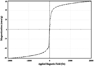
The magnetic properties of the magnetite capped with AMO, such as saturation magnetization (Ms), remnant magnetization (Mr) and coercivity (Hc), were determined from VSM magnetic hysteresis loops (Fig. 7). superoleophilicThe Ms, Mr and Hc values are 59.89 emu g−1, 0.12 emu g−1, and 4.38 G, respectively. These data confirm that the magnetite capped with AMO is superparamagnetic due to the increase in Ms and the decrease in Mr and Hc as compared with magnetite capped with surfactants or other ILs.20,28 Accordingly, the magnetite particles capped with AMO could be readily separated from solution using an external magnet due to their superparamagnetism and large saturation magnetization.
The porosity of the magnetite particles coated with AMO was identified from pore volume and specific surface area measurements and determined using the standard Brunauer–Emmett–Teller (BET) method.46,47 Nitrogen adsorption–desorption isotherms were measured for the magnetite particles and are shown in the ESI (Fig. S4†). The mesopore volume and specific surface area evaluated from the nitrogen adsorption isotherm are 0.4625 cm3 g−1 and 737.5 m2 g−1 at 0.04–0.2P/Po, respectively. These data confirm the porosity of the prepared magnetite when capped with AMO, which confirms that the iron cations seem to be in the (II) and (III) states in the AMO framework.
The previous data showed that the prepared magnetite particles capped with AMO have superhydrophobic, superparamagnetic and porous surfaces, and thus are suitable for application as an oil spill collector. In this respect, different magnetite to oil ratios (MORs) were used to collect oil from the surface of water as illustrated in the Experimental section. Viscous crude oil based on Arabic heavy crude oil was used. The magnetite was reused for 5 cycles after separation with an external magnet from crude oil diluted with diesel fuel. The oil spill collection efficiencies for different MORs are summarized in Table 1.
| Oil collection sample | CE% at different MORs | |||
|---|---|---|---|---|
1![[thin space (1/6-em)]](https://www.rsc.org/images/entities/char_2009.gif) : :![[thin space (1/6-em)]](https://www.rsc.org/images/entities/char_2009.gif) 10 10 |
1![[thin space (1/6-em)]](https://www.rsc.org/images/entities/char_2009.gif) : :![[thin space (1/6-em)]](https://www.rsc.org/images/entities/char_2009.gif) 20 20 |
1![[thin space (1/6-em)]](https://www.rsc.org/images/entities/char_2009.gif) : :![[thin space (1/6-em)]](https://www.rsc.org/images/entities/char_2009.gif) 25 25 |
1![[thin space (1/6-em)]](https://www.rsc.org/images/entities/char_2009.gif) : :![[thin space (1/6-em)]](https://www.rsc.org/images/entities/char_2009.gif) 50 50 |
|
| Cycle 1 | 100 | 98 | 95 | 90 |
| Cycle 2 | 100 | 96 | 93 | 88 |
| Cycle 3 | 98 | 95 | 92 | 86 |
| Cycle 4 | 96 | 93 | 90 | 80 |
| Cycle 5 | 96 | 93 | 90 | 80 |
The data show a high collection efficiency at a low magnetite content (MOR 1![[thin space (1/6-em)]](https://www.rsc.org/images/entities/char_2009.gif) :
:![[thin space (1/6-em)]](https://www.rsc.org/images/entities/char_2009.gif) 50) for the first time. Moreover, the prepared magnetite capped with AMO has a higher reuse efficiency than that reported in the literature.21 Magnetic polymer composites based on the curing of alkyd resin with toluene diisocyanate in the presence iron oxide have previously been used to remove oil for the cleaning-up of oil spills.48 In the best case, one part of the magnetic polymer composite could be used to remove more than eight parts of oil from water with an efficiency of 90%.48 Magnetic polymer composites based on styrene divinyl benzene have also been used to remove oil from the surface of water with a capacity of 3.3 g of oil per g of magnetic composite.49 It was also reported that the capping of magnetite with natural products based on cardanol–furfuraldehyde nanocomposites could be used to achieve the removal of 10 g of petroleum from water.50 Finally, we can conclude that the formation of porous and uniform magnetite nanoparticles without other iron oxide particles increased the magnetic properties of magnetite and improved its efficiency to remove more oil when capped with a hydrophobic IL.
50) for the first time. Moreover, the prepared magnetite capped with AMO has a higher reuse efficiency than that reported in the literature.21 Magnetic polymer composites based on the curing of alkyd resin with toluene diisocyanate in the presence iron oxide have previously been used to remove oil for the cleaning-up of oil spills.48 In the best case, one part of the magnetic polymer composite could be used to remove more than eight parts of oil from water with an efficiency of 90%.48 Magnetic polymer composites based on styrene divinyl benzene have also been used to remove oil from the surface of water with a capacity of 3.3 g of oil per g of magnetic composite.49 It was also reported that the capping of magnetite with natural products based on cardanol–furfuraldehyde nanocomposites could be used to achieve the removal of 10 g of petroleum from water.50 Finally, we can conclude that the formation of porous and uniform magnetite nanoparticles without other iron oxide particles increased the magnetic properties of magnetite and improved its efficiency to remove more oil when capped with a hydrophobic IL.
4. Conclusions
Superhydrophobic magnetite was prepared using hydrophobically modified 1-allyl-3-immidazolium oleate ionic liquid. The prepared magnetite nanoparticles showed monodispersity and superparamagnetic characteristics. Moreover, the produced magnetite has a mesoporous structure and achieved high oil collection efficiencies at low concentrations. These findings may provide a cheap available method to produce magnetite capped with AMO on an industrial scale to collect large areas of oil spills.Acknowledgements
The authors extend their appreciation to the Deanship of Scientific Research at King Saud University for funding this work through research group No. (RGP-235).Notes and references
- United States Coast Guard, On scene coordinator report deep water horizon oil spill, 2011, pp. 1–244 Search PubMed.
- T. R. Annunciado, T. H. D. Sydenstricker and S. C. Amico, Mar. Pollut. Bull., 2005, 50, 1340–1346 CrossRef CAS PubMed.
- A. Bayat, S. F. Aghamiri, A. Moheb and G. R. Vakili-Nezhaad, Chem. Eng. Technol., 2005, 28, 1525–1528 CrossRef CAS.
- M. Cheng, Y. Gao, X. Guo, Z. Shi, J. F. Chen and F. Shi, Langmuir, 2011, 27, 7371–7375 CrossRef CAS PubMed.
- A. M. Atta, R. A. M. El-Ghazawy, R. K. Farag and A. A. Abdel-Azim, React. Funct. Polym., 2006, 66, 931–943 CrossRef CAS.
- A. M. Al-Sabagh and A. M. Atta, J. Chem. Technol. Biotechnol., 1999, 74, 1075–1081 CrossRef CAS.
- A. M. Atta, W. Brostow, T. Datashvili, R. A. El-Ghazawy, H. E. Hagg Lobland, A. M. Hasanb and J. M. Perez, Polym. Int., 2013, 62, 116–126 CrossRef CAS.
- T. Arbatan, X. Fang and W. Shen, Chem. Eng. J., 2011, 166, 787–791 CrossRef CAS.
- A. M. Atta, W. Brostow, H. E. H. Lobland, A. M. Hasan and J. M. Perez, RSC Adv., 2013, 3, 25849–25857 RSC.
- X. Dong, J. Chen, Y. Ma, J. Wang, M. B. Chan-Park and X. Liu, Chem. Commun., 2012, 48, 10660–10662 RSC.
- H. Bi, X. Xie, K. Yin, Y. Zhou, S. Wan and L. He, Adv. Funct. Mater., 2012, 22, 4421–4425 CrossRef CAS.
- J. Wu, N. Wang, L. Wang, H. Dong, Y. Zhao and L. Jiang, ACS Appl. Mater. Interfaces, 2012, 4, 3207–3212 CAS.
- X. Gui, H. Li, K. Wang, J. Wei, Y. Jia and Z. Li, Acta Mater., 2011, 59, 4798–4804 CrossRef CAS.
- C. F. Wang and S. J. Lin, ACS Appl. Mater. Interfaces, 2013, 5, 8861–8864 CAS.
- Q. Zhu, Q. Pan and F. Liu, J. Phys. Chem. C, 2011, 115, 17464–17470 CAS.
- X. Gui, Z. Zeng, Z. Lin, Q. Gan, R. Xiang and Y. Zhu, ACS Appl. Mater. Interfaces, 2013, 5, 5845–5850 CAS.
- A. M. Atta and Z. F. Akl, Mater. Chem. Phys., 2015, 163, 253–261 CrossRef CAS.
- A. M. Atta, H. A. Al-Lohedan and S. A. Al-Hussain, Int. J. Mol. Sci., 2015, 16, 6911–6931 CrossRef CAS PubMed.
- Z. F. Akl, S. M. El-Saeed and A. M. Atta, J. Ind. Eng. Chem., 2016, 34, 105–116 CrossRef CAS.
- A. M. Atta, H. A. Al-Lohedan, A. O. Ezzat, Z. Eissa and A. B. Oumi, J. Polym. Res., 2016, 23, 69 CrossRef.
- M. S. Abdullah, H. A. Al-Lohedana and A. M. Atta, RSC Adv., 2016, 6, 59242–59249 RSC.
- C. Vollmer and C. Janiak, Coord. Chem. Rev., 2011, 255, 2039–2057 CrossRef CAS.
- S. Yin, Z. Luo, J. Xia and H. Li, J. Phys. Chem. Solids, 2010, 71, 1785–1788 CrossRef CAS.
- J. Wanga, M. Yaob, G. Xua, P. Cuia and J. Zhao, Mater. Chem. Phys., 2009, 113, 6–9 CrossRef.
- Y. Zhai, F. Liu, Q. Zhang and G. Gao, Colloids Surf., A, 2009, 332, 98–102 CrossRef CAS.
- L. Li, Y. Huang, G. Yan, F. Liu, Z. Huang and Z. Ma, Mater. Lett., 2009, 63, 8–10 CrossRef CAS.
- X. Zhenga, L. Hea, Y. Duana, X. Jianga, G. Xianga, W. Zhaoa and S. Zhangb, J. Chromatogr. A, 2014, 1358, 39–45 CrossRef PubMed.
- X. Liu, X. Lu, Y. Huang, C. Liu and S. Zhao, Talanta, 2014, 119, 341–347 CrossRef CAS PubMed.
- S. Sun and H. Zeng, J. Am. Chem. Soc., 2002, 124, 8204–8205 CrossRef CAS PubMed.
- P. Migowski and J. Dupont, Chem.–Eur. J., 2007, 13, 32–39 CrossRef CAS PubMed.
- A. Taubert and Z. Li, Dalton Trans., 2007, 7, 723–727 RSC.
- J. N. C. Lopes and A. A. Padua, J. Phys. Chem. B, 2006, 110, 3330–3335 CrossRef PubMed.
- G. H. Min, T. Yim, H. Y. Lee, D. H. Huh, E. Lee, J. Mun, S. M. Oh and Y. G. Kim, Bull. Korean Chem. Soc., 2006, 27, 847–852 CrossRef CAS.
- X. Zheng, S. Luo, L. Zhangb and J. P. Cheng, Green Chem., 2009, 11, 455–458 RSC.
- Q. Zhang, H. Su, J. Luo and Y. Wei, Green Chem., 2012, 14, 201–208 RSC.
- J. D. Scholten, B. C. Leal and J. Dupont, ACS Catal., 2012, 2, 184–200 CrossRef CAS.
- J. Rockenberger, E. C. Scher and P. A. Alivisatos, J. Am. Chem. Soc., 1999, 121, 11595–11596 CrossRef CAS.
- T. Hyeon, S. S. Lee, J. Park, Y. Chung and H. B. Na, J. Am. Chem. Soc., 2001, 123, 12798–12801 CrossRef CAS PubMed.
- S. Sun and H. Zeng, J. Am. Chem. Soc., 2002, 124, 8204–8205 CrossRef CAS PubMed.
- H. Hu, H. Yang, P. Huang, D. Cui, Y. Peng, J. Zhang, F. Lu, J. Liand and D. Shi, Chem. Commun., 2010, 46, 3866–3868 RSC.
- A. M. Atta, H. A. Al-Lohedan and S. A. Al-Hussain, Int. J. Mol. Sci., 2015, 16, 6911–6931 CrossRef CAS PubMed; A. M. Atta, H. A. Al-Lohedan and S. A. Al-Hussain, Dig. J. Nanomater. Biostruct., 2016, 11, 185–198 Search PubMed.
- C. Barrera, A. P. Herrera and C. Rinaldi, J. Colloid Interface Sci., 2009, 329, 107–113 CrossRef CAS PubMed.
- L. Zhang, R. He and H. Gu, Appl. Surf. Sci., 2006, 253, 2611–2617 CrossRef CAS.
- J. W. Krumpfer and T. J. McCarthy, Faraday Discuss., 2010, 146, 103 RSC.
- L. Gao and T. J. McCarthy, Langmuir, 2006, 22, 6234 CrossRef CAS PubMed.
- S. Brunauer, P. H. Emmett and E. Teller, J. Am. Chem. Soc., 1938, 60, 309–319 CrossRef CAS.
- M. Jaroniec, in Access in Nanoporous Materials, ed. T. J. Pinnavaia and M. F. Thorpe, Plenum Press, New York, 1995, pp. 225–272 Search PubMed.
- F. G. de Souza Jr, J. A. Marins, C. H. M. Rodrigues and J. C. Pinto, Macromol. Mater. Eng., 2010, 295, 942–948 CrossRef.
- J. Gua, W. Jiang, F. Wang, M. Chen, J. Mao and T. Xie, Appl. Surf. Sci., 2014, 301, 492–499 CrossRef.
- A. Varela, G. Oliveira, F. G. Souza Jr, C. H. M. Rodrigues and M. A. S. Costa, Polym. Eng. Sci., 2013, 53, 44–51 CAS.
Footnote |
| † Electronic supplementary information (ESI) available. See DOI: 10.1039/c7ra02426f |
| This journal is © The Royal Society of Chemistry 2017 |


