 Open Access Article
Nitrogen-doped reduced graphene oxide intertwined with V2O3 nanoflakes as self-supported electrodes for flexible all-solid-state supercapacitors
Z. Q. Hou *,
Z. Y. Wang,
L. X. Yang and
Z. G. Yang
School of Chemistry and Chemical Engineering, Zhoukou Normal University, Henan 466001, P. R. China. E-mail: houzq@hust.edu.cn
First published on 12th May 2017
Abstract
Flexible all-solid-state supercapacitors (SCs) have great potential applications in flexible and wearable electronics because of their safety, high power density, flexibility, and portability. Herein, a self-supported film electrode comprising nitrogen-doped reduced graphene oxide intertwined with vanadium trioxide nanoflakes (V2O3/N-rGO) was fabricated. The V2O3 nanoflakes have abundant active sites accessible to charge storage, and nitrogen-doped reduced graphene oxide provides a flexible support. The V2O3/N-rGO film electrodes exhibit high conductivity, short diffusion length for ions and electrons, and robust flexibility, resulting in excellent capacitive properties and flexibility. The flexible V2O3/N-rGO film electrode has a high areal capacitance of 216 mF cm−2 at a current density of 1 mA cm−2. All-solid-state flexible SCs assembled by sandwiching two self-supported V2O3/N-rGO hybrid electrodes with alkaline poly(vinyl alcohol) (PVA) and LiCl gel electrolyte show an ideal volumetric capacitance of 8.1 F cm−3, an energy density of 0.55 mW h cm−3, and a power density of 0.035 W cm−3 at a current density of 0.1 A cm−3, based on the entire cell. This indicates that the self-supported V2O3/N-rGO film electrodes have great potential applications in portable and wearable flexible electronics due to their high capacitance, high energy/power density, and good mechanical flexibility.
1. Introduction
The flexible and wearable electronic products such as bendable mobiles phones, flexible sensors, and wearable devices have gained intense research focus due to the increasing demand of flexible energy storage devices in our daily life.1–4 An ideal flexible supercapacitor should not only provide a flexible, lightweight, easily portable, and environmentally friendly power source, but also possess excellent electrochemical properties including a fast charge–discharge rate, high power density, and long cyclic life. Thus, the electrochemical properties of the flexible SCs should not be affected by the mechanical actions such as folding, bending, and other deformation actions. To fulfill these requirements, the key is to design a flexible electrode with robust mechanical strength and high capacitance because the electrode materials are the key components of SCs.Generally, SCs can be classified into electrical double-layer capacitors (EDLC) and pseudocapacitors based on the charge storage mechanism. The charge storage of EDLCs is achieved via reversible ion adsorption/desorption on a large-surface-area that usually produce limited specific capacitance. The electrode materials such as carbon nanotubes and graphene usually provide low specific capacitance. In addition, the pseudocapacitors store charge through a fast reversible faradaic process of redox reactions, which may provide higher specific capacitance. Pseudocapacitive materials such as transition metal oxides (MnO2,5,6 NiO,7 Co3O4,8 Fe2O3,9 MoO3,10 and V2O5 (ref. 11)) and conduction polymers including polypyrrole12 and polyaniline13 can deliver higher capacitance than carbon materials. However, the low electron conductivity of metal oxides and kinetic irreversibility associated with conducting polymers lead to a low rate capability and cycling stability. In recent years, transition metal carbides or nitrides have been demonstrated as electrode materials for SCs due to their high electrical conductivity, impressive specific capacitance, and chemical stability.14–18 However, the synthesis of transition metal carbides or nitrides usually require high temperature and long reaction times, which do not meet the requirements for green synthesis methods.
Thus, capacitor materials with the good conductivity and high specific capacitance as well as fabricated using green synthesis methods are highly desired. Fortunately, vanadium-based oxide phases of V2O3 exhibit quasi-metallic conductivity of 103 Ω−1 cm−1, close to that of Ru2O.19 Therefore, V2O3, as well as VN, may also be a great candidate to develop fast ECs with high-power and high-energy densities. Li et al. have reported that V2O3@C composites exhibit a specific capacitance of 205 F g−1 at 0.05 A g−1 over a potential range of −0.4–0.6 V.20 However, a graphene-bridged V2O3/VOx core–shell composite as an electrode material was fabricated by Xuan Pan, which exhibited a specific capacitance of 590 F g−1 at 5 mV s−1 and high-power and high-energy densities.19 The reason is that V2O3 has a high conductivity, and V2O3/VOx core–shell structure provides high capacitance. Hence, V2O3 could be a great candidate for developing fast supercapacitors with excellent electrochemical performance.
Herein, we report the synthesis of nitrogen-doped reduced graphene oxide intertwined with V2O3 nanoflakes to form a self-supported film electrode suitable for flexible all-solid-state SCs. The self-supported V2O3/N-rGO film electrode comprised nitrogen-doped reduced graphene oxide intertwined with V2O3 nanoflakes (V2O3/N-rGO) without the introduction of any mechanical support or foreign binder. The flexible V2O3/N-rGO film electrodes have several advantages to achieve high electrochemical performance. First, the V2O3 nanoflakes provide more active sites accessible to charge storage, leading to high specific capacitance. In addition, nitrogen-doped reduced graphene oxide also participates in charge storage. Second, nitrogen-doped reduced graphene oxide intertwined with V2O3 nanoflakes has a robust mechanical infrastructure, which is compatible with the intrinsic rigidity of V2O3, leading to robust flexibility and mechanical integrity of the V2O3/N-rGO film. Third, the interconnected framework of the V2O3/N-rGO film electrodes provide high conductivity and short diffusion length for ions and electrons, resulting in impressive capacitance. Fourth, the contact between V2O3 and N-rGO results in a much higher contact area at the interface, which can be beneficial for good dispersion without size variation or any agglomeration and retaining the structure during the charge–discharge process, which can help in achieving excellent cycling stability.21–24 As a consequence, the self-supported V2O3/N-rGO film electrodes deliver a high areal capacitance of 216 mF cm−2 at a current density of 1 mA cm−2. The all-solid-state flexible SCs fabricated by sandwiching two self-supported film electrodes with a LiCl/PVA gel electrolyte show an ideal volumetric capacitance of 8.1 F cm−3 at a current density of 0.1 A cm−3, a high energy density of 0.55 mW h cm−3 at a power density of 0.035 W cm−3, and excellent cycling stability. These values are higher than most of the previously reported results obtained from quasi and all-solid-state flexible SCs, demonstrating the great commercial potential of the present all-solid-state flexible SCs in portable or wearable devices.
2. Experimental
2.1 Preparation of the V2O5 gel
All chemical reagents were purchased and used without further purification. The flaky V2O5 xerogel was prepared using a typical hydrothermal method. For example, 0.24 g of V2O5 powder was dispersed in 20 mL of H2O followed by the addition of 10 mL of H2O2 (30%) under vigorous stirring for 2 h.25 The obtained orange solution was transferred to a 50 mL Teflon-lined autoclave. The autoclave was sealed and heated in an oven at 205 °C for 16 h. Finally, the brownish red gel was obtained.2.2 Fabrication of the self-supported V2O3/N-rGO hybrid film
The flexible self-supported hybrid films were fabricated using a vacuum filtration method. First, the desired GO powders were sonicated in 15 mL of DI water for 60 min using a probe sonicator. Then, the desired V2O5 gel was added dropwise to the GO suspension and sonicated for 30 min to ensure sufficient mixing of the materials. The suspension was filtered through a filter membrane (220 nm pore size). After vacuum drying at 70 °C for 60 min, the self-supported V2O5 gel/GO hybrid film was peeled from the filtration membrane and was further annealed at 500 °C for 30 min under an NH3 atmosphere to obtain the self-supported V2O3/N-rGO hybrid film. For comparison, the V2O3/N-rGO hybrid films were prepared by the annealing of V2O5 gel/GO films (with various mass ratios of V2O5 gel and GO) under an NH3 atmosphere via the same procedure.2.3 Fabrication of the half-cell and flexible all-solid-state symmetric devices
To optimize the electrochemical performance of the V2O3/N-rGO electrodes, the V2O3/N-rGO electrodes were investigated using three-electrode cells because they were simple and maneuverable. In the three-electrode configuration, the cell was equipped with V2O3/N-rGO as the working electrode, a saturated SCE as a the reference electrode, and a Pt plate as the counter electrode in a 1 M Na2SO4 electrolyte. All the all-solid-state supercapacitor devices studied for material performance in this study were fabricated using a two-electrode standard method. The LiCl/PVA gel was prepared as follows: 3 g of PVA was mixed with 30 mL of LiCl (5 M) aqueous solution and heated at 85 °C for 1 h under vigorous stirring.6 Herein, two pieces of the self-supported V2O3/N-rGO hybrid electrodes with a separator were sandwiched with LiCl/PVA gel as the solid-state electrolyte. Prior to assembly, the two self-supported V2O3/N-rGO hybrid electrodes and separator were immersed in the LiCl//PVA solution for 10 min. The devices were solidified at room temperature for 1 h and then placed under 40 °C and vacuum conditions to remove excess water.2.4 Characterization
The morphology, structure, and composition of the samples were determined via field-emission scanning electron microscopy (FE-SEM, FEI, Nova 450 Nano), high-resolution transmission electron microscopy (HRTEM, TECNAI), X-ray diffraction using Cu Kα radiation (λ = 1.5418 Å) (XRD, Philips, X′ Pert Pro), and XPS (ESCALB MK-ll).2.5 Electrochemical measurements
The three-electrode set-up in 1 M Na2SO4 used for the single electrode tests comprised Hg/Hg2SO4 and platinum flake as the reference and counter electrodes, respectively. The mass loading of the active materials in each electrode was 1.05 mg cm−2. The electrochemical performances of the V2O3/N-rGO hybrid electrodes and all-solid-state symmetrical devices were tested using an electrochemical station (CHI 660E). The areal capacitance Cs (mF cm−2), volumetric capacitance Cvol (F cm−3), energy density E (mW h cm−3), and power density (mW cm−3) were calculated using the following equations:16| C = IΔt/ΔE | (1) |
| CS = C/S = IΔt/SΔE | (2) |
| Cv = C/V = IΔt/VΔE | (3) |
| E = CU2/2V | (4) |
| P = E/t | (5) |
3. Results and discussion
Fig. 1 demonstrates the fabrication process of the flexible V2O3/N-rGO film electrodes and the flexible all-solid-state SCs. First, the GO powders were sonicated in DI water and the V2O5 xerogel was synthesized using a hydrothermal method.25 Then, a mixture of the GO suspension and V2O5 xerogel was obtained via ultrasonication. Second, the freestanding V2O5 xerogel/GO films were obtained by vacuum filtering the mixture and subsequently peeled off from the filter membrane after drying at 70 °C for 1 h. Finally, the flexible V2O3/N-rGO hybrid films were produced by thermally annealing the V2O5 xerogel/GO films at 500 °C for 30 min under an NH3 atmosphere. The all-solid-state flexible SCs based on two symmetrical V2O3/N-rGO hybrid film electrodes were assembled using the LiCl/PVA gel electrolyte.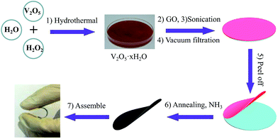 | ||
| Fig. 1 Schematic of the fabrication of the flexible and self-supported V2O3/N-rGO film electrodes and the assembly of the all-solid-state flexible SCs devices. | ||
The XRD pattern of the product obtained by annealing the V2O5 xerogel and the freestanding V2O5 xerogel/GO film in an NH3 atmosphere at 500 °C for 30 min is presented in Fig. 2. The XRD pattern of the product obtained by annealing V2O5 xerogel can be well attributed to the hexagonal structure of V2O3 (JCPDS no. 34-0187), as shown in Fig. 1a.25 For the composites obtained by annealing V2O5 xerogel/GO, the XRD pattern shows the features of board peaks above a diffuse background, indicating a poor crystalline quality (Fig. 1b). The XRD diffraction peak at 26° corresponds to N-doped reduced graphene oxide26 (See XPS characterization). The other diffraction peaks can be indexed to the hexagonal structure of V2O3 (JCPDS no. 34-0187). This suggests that the V2O5 xerogel and GO in the V2O5 xerogel/GO film after thermal treatment produce V2O3 and N-rGO, respectively. In addition, the diffraction peaks of V2O3 are broadened due to the doping of N-rGO. This indicates that V2O3/N-rGO was obtained by annealing the V2O5 xerogel/GO film under an NH3 atmosphere at 500 °C for 30 min.
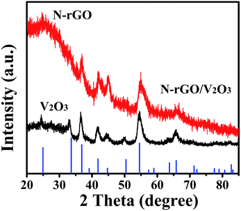 | ||
| Fig. 2 The XRD patterns of the composites and the standard V2O3 (corundum structure) pattern (JCPDS Card No. 34-0187). | ||
Fig. 3a shows the SEM images of the self-supported V2O3/N-rGO film. It can be observed that the surface of the film shows a wrinkled structure due to GO and graphene-like V2O5 xerogel. The cross-section SEM image shows that the self-supported V2O3/N-rGO film has a thickness of about 20 μm, and the V2O3 nanosheets intertwined with N-rGO nanosheets were uniformly distributed in the self-supported V2O3/N-rGO film (Fig. 3b). The V2O3/N-rGO film was further characterized by TEM and HR-TEM. The TEM images depicted in Fig. 3c show that the composite has a wrinkled structure due to the N-rGO nanosheets. The nanosheets are clearly observed in Fig. 3c. Fig. 3d indicates that the V2O3 nanosheet is a single-crystal, and the lattice fringe spacing is 0.205 nm, which is consistent with the spacing of the (202) plane of V2O3. In addition, N-rGO becomes disorientated due to the structural distortions caused by the intercalation of the nitrogen atoms into its graphitic plans.26 This provides more information about the V2O3/N-rGO composite structure.
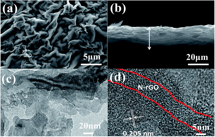 | ||
| Fig. 3 (a) and (b) SEM images of the V2O3/N-rGO samples. (c) and (d) TEM and HR-TEM images of the V2O3/N-rGO samples, respectively. | ||
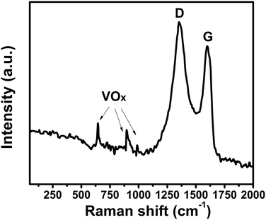
To further investigate the V2O3/N-rGO sample, Raman spectroscopy was conducted to characterize the composition (Fig. 4). The Raman peaks at 1355 and 1588 cm−1 originate from N-doped reduced graphene oxide. The Raman peaks at 645, 901, and 990 cm−1 were attributed to VOx (ref. 25, 27 and 28) in the V2O3 sample. The reason is that the surface of V2O3 is naturally oxidized to V4+ and V5+ under ambient conditions.19 This indicates that the Raman spectra of the V2O3/N-rGO composites exhibits little V4+ and V5+ coated on V2O3 and the characteristic peaks of N-doped reduced graphene oxide.
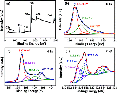
Fig. 5a is the spectra of the typical XPS survey scans of the NH3-treated graphene–vanadium oxide xerogel composites, in which C, N, O, and V can be apparently identified. The XPS survey spectra indicates that V2O3/N-rGO contains only C, V, N, and O graphite-like sp2 C, N-sp2 C, and N-sp3 C corresponding to 284.9, 286.7, and 287.7 eV, respectively.29 In addition, most of the C atoms in the N-doped graphene are arranged in a conjugated honeycomb lattice without other detectable impurities on their surface. Fig. 5b compares the high-resolution C 1s XPS spectra of the samples. It indicates that the carbon element of the sample originates from the main peak at 284.9 eV. The high-resolution N 1s spectra show five different states (Fig. 5c). The peak at 397.0 eV was attributed to the N atom from vanadium oxynitride (P1). The other three peaks at 398.3, 400.1, and 401.7 eV were ascribed to pyridinic nitrogen, pyrrolic nitrogen, and quaternary nitrogen in the outer shell.29 The high-resolution V 2p XPS peak in Fig. 5d shows the four chemical states of V: the peak at 515.0 eV was attributed to V–N–O14 and the peaks at 516.0, 516.9, and 517.6 eV were attributed to V3+, V4+, and V5+, respectively. The existence of V4+ and V5+ in the V2O3/N-rGO samples is a result of the inevitable oxidation of surface V2O3 when it is exposed to air.19
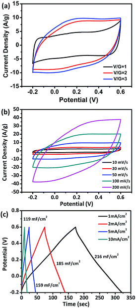
The electrochemical properties of the flexible V2O3/N-rGO films were evaluated using a three-electrode system in a 1 M Na2SO4 aqueous electrolyte with Hg/Hg2SO4 as the reference electrode and Pt plate as the counter electrode. Fig. 6a shows the CV curves obtained for the electrodes with various ratios of V/G = 1, V/G = 2, and V/G = 3 at a scan rate of 50 mV s−1. The CV curve obtained for the V2O3/N-rGO film electrode (V/G = 1) was close to rectangular in shape at a potential of −0.2–0.6 V. In addition, the CV area of the V2O3/N-rGO film electrode (V/G = 3) is the greatest among all the samples, revealing its great specific capacitance. Herein, the flexibility of the film becomes poor for the V/G = 4 electrode; thus, the optimal ratio of V/G for the V2O3/N-rGO film electrodes was determined to be 3. Fig. 6b indicates the most specific capacitance of the flexible V2O3/N-rGO films electrode (V/G = 3) in the potential range between −0.2 and 0.6 V at a scanning rate ranging from 10 to 200 mV s−1. The galvanostatic charge–discharge (GCD) curves exhibit a slight curvature and symmetrical triangular shape without evident voltage drops between 1 and 10 mA cm−2, suggesting good pseudocapacitive behavior. The flexible freestanding V2O3/N-rGO electrode shows a substantial areal capacitance of 216 mF cm−2 (206 F g−1 based on the entire mass of the electrode) at a current density of 1 mA cm−2 (Fig. 6c). It is higher than the previously reported results: MVN@VN NWs electrode (196 F g−1 at 1.44 mA cm−2),14 Fe2O3 nanotube-based electrodes (180.4 mF cm−2 at 1.1 mA cm−2),30 self-supported mesoporous VN/CNTs hybrid electrode (178 mF cm−2 at 1.1 mA cm−2),31 MMNNBs/rGO hybrid electrode (142 mF cm−2 at 1 mA cm−2),16 and hydrogenated ZnO core/shell nanoscable electrodes (138.7 mF cm−2 at 1 mA cm−2).32 Moreover, 55% of the capacitance was retained when the current density was increased 10 times from 1 to 10 mA cm−2. This indicates that the V2O3/N-rGO electrode suffers from severe capacitance decay because of the solubility of V2O3 during the process of the electrochemical measurements. Thus, the electrolyte becomes slightly yellow due to the formation of V5+.
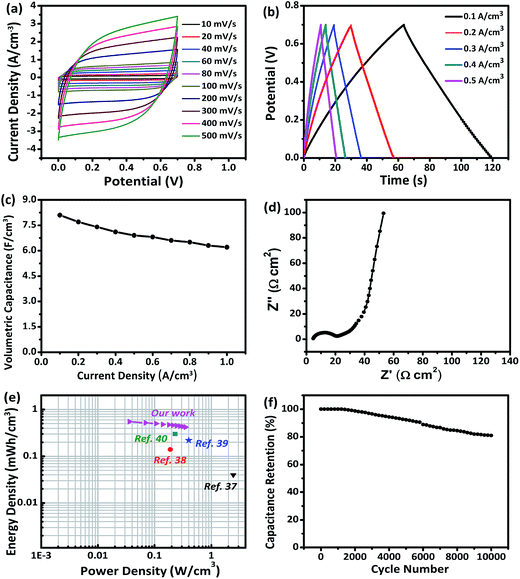
The self-supported V2O3/N-rGO film electrode has good flexibility, high specific capacitance, low rate capability, and low cycling stability, caused by the solubility of V2O3 in the aqueous solution system. However, the high solubility can be improved using a solid-state electrolyte. Thus, the self-supported V2O3/N-rGO film electrode is a promising candidate for high performance flexible SCs. To meet the practical requirements of a flexible electrode, a flexible all-solid-state SC composed of two self-supported V2O3/N-rGO film electrodes and a LiCl/PVA gel electrolyte was assembled, as illustrated in Fig. 1. Fig. 7a depicts the CV curves obtained for the assembled V2O3/N-rGO//V2O3/N-rGO symmetrical devices in the voltage range of 0–0.7 V at the scanning rates between 10 and 500 mV s−1. The CV curves exhibit a nearly rectangular shape and mirror image with respect to the zero-current line, even at a large scanning rate from 100 to 500 mV s−1, indicating superior capacitive behavior and high rate capability. The GCD curves obtained for the all-solid-state SCs at various current densities from 0.1 to 0.5 A cm−3 are shown in Fig. 7b. The capacitance of the devices was calculated to be 8.1 and 6.9 F cm−3 at the current density of 0.1 and 0.5 A cm−3, respectively. These values are higher than those for the previously reported flexible solid-state SCs such as hydrogenated ZnO@MnO2//Fe2O3 asymmetrical SCs (1.21 F cm−3 at 6.3 mA cm−3),33 functionalized carbon-nanotube-based SCs (3.0 F cm−3 at 0.133 mA cm−3),34 N-rGO-based SCs (3.4 F cm−3 at 20 mA cm−3),35 and a free-standing mesoporous VN/CNTs film electrode-based SCs (7.9 F cm−3 at 25 mA cm−3).31 Moreover, the device had superior rate capability with 76% capacity retention when the current density was varied from 0.1 to 1 A cm−3 (Fig. 7c). The electrochemical impedance spectra of the solid-state devices are presented in Fig. 7d. The Nyquist plot exhibits a nearly vertical line along the imaginary axis in the low frequency region, and the equivalent series resistance of the devices was about 5 Ω cm2, revealing the excellent capacitor behavior of the device. The energy density E and power density P are the key parameters for the flexibility of the SCs in practical applications. Herein, the E and P values of the all-solid-state SCs were calculated and are listed in Fig. 7e. The E and P values of other previously reported devices are also presented in Fig. 7e for comparison. The volumetric energy density (0.55 mW h cm−3) of the devices described in this study is higher than that of some previously reported devices constructed from quasi and all-solid-state SCs such as carbon nanotube-based SCs H–ZnO NW-based SCs (0.04 mW h cm−3, PVA/LiCl),36 carbon microfiber bundles coated with multi-walled CNT-based SCs (0.14 mW h cm−3, PVA/H3PO4),37 carbon/MnO2 core–shell fiber-based SCs (0.22 mW h cm−3, PVA/H3PO4),38 and H–TiO2/MnO2//H–TiO2/C-based SCs (0.3 mW h cm−3, PVA/LiCl).39 The all-solid-state device based on the V2O3/N-rGO film electrodes and a LiCl/PVA gel electrolyte exhibited remarkable long-term cycling stability at a current density of 1 A cm−3, and there was only a 19% decrease in the capacitance after 10![[thin space (1/6-em)]](https://www.rsc.org/images/entities/char_2009.gif) 000 cycles, as presented in Fig. 7f, indicating its relatively high stability. Thus, the all-solid-state SCs exhibit excellent energy storage performance due to the excellent capacitive properties of the self-supported V2O3/N-rGO film electrode coupled with the matching PVA/LiCl gel electrolyte.
000 cycles, as presented in Fig. 7f, indicating its relatively high stability. Thus, the all-solid-state SCs exhibit excellent energy storage performance due to the excellent capacitive properties of the self-supported V2O3/N-rGO film electrode coupled with the matching PVA/LiCl gel electrolyte.
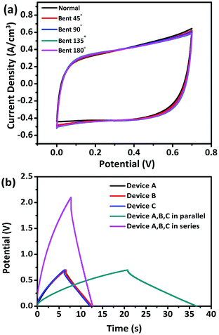
To evaluate the potential of our devices as flexible energy storage components in flexible/wearable electronics, CV tests were performed under different bending conditions. Fig. 8a exhibits no obvious change in the CV curves obtained under various bending conditions of 45°, 90°, 135°, and 180°, revealing the excellent flexibility. To further demonstrate the feasibility, three identical devices were connected in series or parallel to construct devices. The three units were denoted as A, B, and C, respectively. The charging/discharging voltage window of the three devices connected in series was 2.1 V with almost the same discharging time as a single device. The charging time of the three devices in parallel was about 2.82 times longer than that of a single device, which is close to the theoretical value of 3, thereby conforming to the theorem of series and parallel connections of capacitors (Fig. 8b). This demonstration indicates the great potential of the V2O3/N-rGO film electrodes for practical applications in flexible electrochemical energy-storage devices.
4. Conclusions
In summary, a self-supported V2O3/N-rGO film electrode comprising nitrogen-doped reduced graphene oxide intertwined with V2O3 nanoflakes was prepared using a facile and effective method; this method consisted of the hydrothermal formation of V2O5 xerogel with subsequent mixing with a GO suspension, vacuum filtration, and annealing under an NH3 atmosphere. The V2O3 nanosheets have abundant active sites for charge storage, and nitrogen-doped reduced graphene oxide intertwined with V2O3 provide a flexible support. This indicates that the V2O3/N-rGO electrodes have abundant active sites, good mechanical integrity, and flexibility, resulting in high ion diffusion and electron transfer, and high capacity and high rate capability. The flexible V2O3/N-rGO film electrodes exhibit a high areal capacitance of 216 mF cm−2 at a current density of 1 mA cm−2. The all-solid-state flexible SCs fabricated by sandwiching two self-supported V2O3/N-rGO film electrodes with a PVA/LiCl gel electrolyte deliver an ideal volumetric capacitance of 8.1 F cm−3, an energy density of 0.55 mW h cm−3, and a power density of 0.035 W h cm−3. Moreover, the flexible all-solid-state devices have excellent cycling stability with 81% of the initial capacitance retention after 10![[thin space (1/6-em)]](https://www.rsc.org/images/entities/char_2009.gif) 000 cycles. Hence, the flexible all-solid-state devices have promising potential in portable/wearable electronics due to their environmentally friendliness, good flexibility, and facile connectivity in series and parallel.
000 cycles. Hence, the flexible all-solid-state devices have promising potential in portable/wearable electronics due to their environmentally friendliness, good flexibility, and facile connectivity in series and parallel.
Acknowledgements
This work was supported by the Key Research Project of Henan Higher Education Institute (15A430055).Notes and references
- G. Q. Ma, Z. Wang, B. Gao, T. P. Ding, Q. Z. Zhong, X. Peng, J. Su, B. Hu, L. Y. Yuan, P. K. Chu, J. Zhou and K. F. Huo, J. Mater. Chem. A, 2015, 3, 14617–14624 CAS.
- X. Wang, X. Lu, B. Liu, D. Chen, Y. Tong and G. Shen, Adv. Mater., 2014, 26, 4763–4782 CrossRef CAS PubMed.
- L. Li, Z. Wu, S. Yuan and X. B. Zhang, Energy Environ. Sci., 2014, 7, 2101–2122 CAS.
- J. Kristy, D. Genevieve and G. Yury, J. Mater. Chem. A, 2014, 2, 10776 Search PubMed.
- J. Liu, L. Zhang, H. B. Wu, J. Lin, Z. Shen and X. W. Lou, Energy Environ. Sci., 2014, 7, 3709–3719 CAS.
- X. Lu, T. Zhai, X. Zhang, Y. Shen, L. Yuan, B. Hu, L. Gong, J. Chen, Y. Gao, J. Zhou, Y. Tong and Z. L. Wang, Adv. Mater., 2012, 24, 938–944 CrossRef CAS PubMed.
- Z. Yang, F. Xu, W. Zhang, Z. Mei, B. Pei and X. Zhu, J. Power Sources, 2014, 246, 24–31 CrossRef CAS.
- X. Wang, M. Li, Z. Chang, Y. Yang, Y. Wu and X. Liu, ACS Appl. Mater. Interfaces, 2015, 7, 2280–2285 CAS.
- Z. Ma, X. Huang, S. Dou, J. Wu and S. Wang, J. Phys. Chem. C, 2014, 118, 17231–17239 CAS.
- H. Ji, X. Liu, Z. Liu, B. Yan, L. Chen, Y. Xie, C. Liu, W. Hou and G. Yang, Adv. Funct. Mater., 2015, 25, 1886–1894 CrossRef CAS.
- B. Saravanakumar, K. K. Purushothaman and G. Muralidharan, ACS Appl. Mater. Interfaces, 2012, 4, 4484–4490 CAS.
- Q. Wang, J. Yan, Z. Fan, T. Wei, M. Zhang and X. Jing, J. Power Sources, 2014, 247, 197–203 CrossRef CAS.
- H. Tang, J. Wang, H. Yin, H. Zhao, D. Wang and Z. Tang, Adv. Mater., 2015, 27, 1117–1123 CrossRef CAS PubMed.
- B. Gao, X. Li, X. Guo, X. Zhang, X. Peng, L. Wang, J. Fu, P. K. Chu and K. Huo, Adv. Mater. Interfaces, 2015, 2, 1500211 CrossRef.
- W. Bi, Z. Hu, X. Li, C. Wu, J. Wu and Y. Xie, Nano Res., 2015, 8, 193–200 CrossRef CAS.
- G. Ma, Z. Wang, B. Gao, T. Ding, Q. Zhong, X. Peng, J. Su, B. Hu, L. Yuan, P. K. Chu, J. Zhou and K. Huo, J. Mater. Chem. A, 2015, 3, 14617–14624 CAS.
- M. R. Lukatskaya, O. Mashtalir, C. E. Ren, Y. Dall'Agnese, P. Rozier, P. L. Taberna, M. Naguib, P. Simon, M. W. Barsoum and Y. Gogotsi, Science, 2013, 341, 1502–1505 CrossRef CAS PubMed.
- Y. Zhong, X. Xia, F. Shi, J. Zhan, J. Tu and H. J. Fan, Adv. Sci., 2016, 1500286 CrossRef PubMed.
- X. Pan, G. Ren, M. Nadim Ferdous Hoque, S. Bayne, K. Zhu and Z. Fan, Adv. Mater. Interfaces, 2014, 1, 1400398 CrossRef.
- H.-Y. Li, K. Jiao, L. Wang, C. Wei, X. Li and B. Xie, J. Mater. Chem. A, 2014, 2, 18806–18815 CAS.
- H. N. Ma, J. He, D. B. Xiong, J. S. Wu, Q. Q. Li, V. Dravid and Y. F. Zhao, ACS Appl. Mater. Interfaces, 2016, 8, 1992–2000 CAS.
- Y. F. Zhao, H. N. Ma, S. F. Huang, X. J. Zhang, M. R. Xia, Y. F. Tang and Z. F. Ma, ACS Appl. Mater. Interfaces, 2016, 8, 22997–23005 CAS.
- Z. Y. Chen, D. B. Xiong, X. J. Zhang, H. N. Ma, M. R. Xia and Y. F. Zhao, Nanoscale, 2016, 8, 6636–6645 RSC.
- Y. F. Zhao, W. Ran, J. He, Y. Z. Huang, Z. F. Liu, W. Liu, Y. F. Tang, L. Zhang, D. W. Gao and F. M. Gao, Small, 2015, 11, 1310–1319 CrossRef CAS PubMed.
- Z. Hou, K. Guo, H. Li and T. Zhai, CrystEngComm, 2016, 18, 3040–3047 RSC.
- L. T. Qu, Y. Liu, J. B. Baek and L. M. Dai, ACS Nano, 2010, 4, 1321–1326 CrossRef CAS PubMed.
- B. Hu, Y. Zhang, W. Chen, C. Xu and Z. L. Wang, Adv. Mater., 2011, 23, 3536–3541 CrossRef CAS PubMed.
- W. J. Shen, K. W. Sun and C. S. Lee, J. Nanopart. Res., 2011, 13, 4929–4936 CrossRef CAS.
- D. C. Wei, Y. Q. Liu, Y. Wang, H. I. Zhang, L. Q. Huang and G. Yu, Nano Lett., 2009, 9, 1752–1758 CrossRef CAS PubMed.
- P. H. Yang, Y. Ding, Z. Y. Lin, Z. W. Chen, Y. Z. Li, P. F. Qiang, M. Ebrahimi, W. J. Mai, C. P. Wong and Z. L. Wang, Nano Lett., 2014, 14, 731–736 CrossRef CAS PubMed.
- X. Xiao, X. Peng, H. Y. Jin, T. Q. Li, C. C. Zhang, B. Gao, B. Hu, K. F. Huo and J. Zhou, Adv. Mater., 2013, 25, 5091–5097 CrossRef CAS PubMed.
- P. Yang, X. Xiao, Y. Li, Y. Ding, P. Qiang, X. Tan, W. Mai, Z. Lin, W. Wu, T. Li, H. Jin, P. Liu, J. Zhang, C. P. Wong and Z. L. Wang, ACS Nano, 2013, 7, 2617–2626 CrossRef CAS PubMed.
- X. Lu, Y. Zeng, M. Yu, T. Zhai, C. Liang, S. Xie, M.-S. Balogun and Y. Tong, Adv. Mater., 2014, 26, 3148–3155 CrossRef CAS PubMed.
- X. Xiao, T. Q. Li, Z. H. Peng, H. Y. Jin, Q. Z. Zhang, Q. Y. Hu, B. Yao, Q. P. Luo, C. F. Zhang, L. Gong, J. Chen, Y. Gogotsi and J. Zhou, Nano Energy, 2014, 6, 1–9 CrossRef CAS.
- S. Y. Liu, J. Xie, H. B. Li, Y. Wang, H. Y. Yang, T. J. Zhu, S. C. Zhang, G. S. Cao and X. B. Zhao, J. Mater. Chem. A, 2014, 2, 18125–18131 CAS.
- P. H. Yang, X. Xiao, Y. Z. Li, Y. Ding, P. F. Qing, X. H. Tan, W. J. Mai, Z. Y. Lin, W. Z. Wu, T. Q. Li, H. Y. Jin, P. Y. Liu, J. Zhou, C. P. Wong and Z. L. Wang, ACS Nano, 2013, 7, 2617–2626 CrossRef CAS PubMed.
- V. T. Le, H. Kim, A. Ghosh, J. Kim, J. Chang, Q. A. Vu, D. T. Pham, J. H. Lee, S. W. Kim and Y. H. Lee, ACS Nano, 2013, 7, 5940–5947 CrossRef CAS PubMed.
- X. Xiao, T. Li, P. Yang, Y. Gao, H. Jin, W. Ni, W. Zhan, X. Zhang, Y. Cao, J. Zhong, L. Gong, W. C. Yen, W. Mai, J. Chen, K. Huo, Y. L. Chueh, Z. L. Wang and J. Zhou, ACS Nano, 2012, 6, 9200–9206 CrossRef CAS PubMed.
- X. Lu, M. Yu, G. Wang, T. Zhai, S. Xie, Y. Ling, Y. Tong and Y. Li, Adv. Mater., 2013, 25, 267–272 CrossRef CAS PubMed.
| This journal is © The Royal Society of Chemistry 2017 |

