 Open Access Article
Biomimetic intrafibrillar silicification of collagen fibrils through a one-step collagen self-assembly/silicification approach†
Changmin Hu b,
Le Yu
 a and
Mei Wei*ab
aDepartment of Materials Science and Engineering, University of Connecticut, Storrs, CT 06269, USA. E-mail: mei.wei@uconn.edu; Fax: +1-860-486-4745; Tel: +1-860-486-5003
bInstitute of Materials Science, University of Connecticut, Storrs, CT 06269, USA
First published on 11th July 2017
Abstract
Inspired by the silicification process in nature, intrafibrillar silicified collagen fibrils were successfully fabricated using a biomimetic one-step collagen self-assembly/silicification approach, in which collagen self-assembly and intrafibrillar silicification occurred simultaneously. To the best of our knowledge, it is the first time that intrafibrillar silicified collagen fibrils were formed via a one-step simultaneous approach, where collagen fibrils served as a templating matrix, and poly(allylamine) hydrochloride and sodium tripolyphosphate acted as the respective positive and negative analogs of zwitterionic proteins. By tailoring zwitterionic proteins analogs, silicified collagen fibrils with different microstructures, including core–shell, twisted and banded structures, were achieved. The intrafibrillar silicified collagen fibrils demonstrated significant improvement in osteoblast proliferation compared with apatite mineralized collagen fibrils. These findings open a new avenue for preparation of silicon-containing hierarchical biocomposites for biomedical needs.
1. Introduction
Silicon is an essential element contributing significantly to the health of bone and cartilage.1 It has been discovered that silicon-containing organic–inorganic biocomposites with unique hierarchical structures exist in numerous natural biological systems, such as bone, fish scales, diatom frustules, and spicules of glass sponges.2–5 For example, the long spicules of Hyalonema sieboldi demonstrate a perfect hierarchical structure, remarkable optical properties, and excellent durability and flexibility.6 More importantly, silicon-containing biomaterials have been found to be osteoinductive for new bone formation and stimulative for neovascularization without supplements of growth factors.7,8 Due to the unique properties of the silicon-containing biomaterials, great enthusiasm has been generated and extensive effort has been made to replicate these materials to be used in different biomedical applications.6,9,10In recent years, effort has been directed to develop an in-depth understanding of the biosilicification mechanism so as to replicate the process in vitro and thereby fabricate organic–inorganic hybrid biomaterials with a hierarchical structure. Chemical analyses of glass sponge and diatom have shown that fibrillar collagen can serve as templates for silicification, while the highly zwitterionic proteins, such as silaffins, silicateins, and long-chain polyamines, are actively involved in the interplay with collagen and the mediation of silicification process.6,11 The zwitterionic proteins exhibit both positive charges introduced by the quaternary ammonium groups and negative charges by the phosphorylated serine residues.12 The zwitterionic nature of these proteins enables them to form aggregates, which controls the silicification process and silica morphology.13 Polyamines have been found to induce silica precipitation in vitro in the presence of polyanions, where polyamines and polyanions act as positive and negative analogs of zwitterionic proteins, respectively.3 Despite all the successes in fabrication of silicon-containing biomaterials, an in-depth understanding of the mechanism of biomimetic silicification process has not yet been achieved.
A variety of silicified collagen hybrids have been produced, such as silica–collagen xerogels, and silicified collagen hydrogels with different silicon sources (silica and silicates).14–18 Typically, silica is formed on the surface of collagen fibrils (extrafibrillar silicification), resulting in a weak bond between silica and collagen.14,15,19 However, the recent successes in intrafibrillar calcification of collagen fibrils have shed light on the understanding of intrafibrillar silicification (forming silica within collagen fibrils), as intrafibrillar calcification and silicification of collagen fibrils may share a similar mechanism. In our previous work, intrafibrillar calcified collagen fibrils have been achieved by a one-step collagen self-assembly and calcification approach.20,21 In the present study, we also propose to produce intrafibrillar silicified collagen fibrils via a one-step collagen self-assembly/silicification (OCSS) approach, where collagen self-assembly and silicification occur simultaneously with the aid of positive and negative analogs of zwitterionic proteins. To test this hypothesis, a systemic study was conducted to investigate the effect of zwitterionic proteins analogs on the OCSS approach, and an in vitro cell culture study was also conducted to test the biocompatibility of the intrafibrillar silicified collagen fibrils.
2. Materials and methods
2.1. Materials
Type I collagen was extracted from rat tails, purified based on the protocol reported by Rajan et al.22 Poly(allylamine) hydrochloride (PAH, Mw = 15![[thin space (1/6-em)]](https://www.rsc.org/images/entities/char_2009.gif) 000 Da) and sodium tripolyphosphate (TPP) were purchased from Sigma-Aldrich. All chemicals were of analytical chemical grade.
000 Da) and sodium tripolyphosphate (TPP) were purchased from Sigma-Aldrich. All chemicals were of analytical chemical grade.
2.2. Preparation of hydrolyzed silicic acid
A 3 wt% hydrolyzed silicic acid stock solution was prepared as followed: Silbond® 40 (40% hydrolyzed tetraethyl orthosilicate (TEOS); Silbond Corp., Weston, MI, USA), absolute ethanol, deionized water (DIW) and 37% HCl were mixed at a molar ratio of 1.03![[thin space (1/6-em)]](https://www.rsc.org/images/entities/char_2009.gif) :
:![[thin space (1/6-em)]](https://www.rsc.org/images/entities/char_2009.gif) 199
199![[thin space (1/6-em)]](https://www.rsc.org/images/entities/char_2009.gif) :
:![[thin space (1/6-em)]](https://www.rsc.org/images/entities/char_2009.gif) 6.11
6.11![[thin space (1/6-em)]](https://www.rsc.org/images/entities/char_2009.gif) :
:![[thin space (1/6-em)]](https://www.rsc.org/images/entities/char_2009.gif) 0.03 and stirred for 1 hour at room temperature to hydrolyze TEOS into orthosilicic acid and its oligomers.23
0.03 and stirred for 1 hour at room temperature to hydrolyze TEOS into orthosilicic acid and its oligomers.23
2.3. Preparation of PAH-stabilized silica (PAH–SA) precursors
PAH-stabilized silica (PAH–SA) precursors were prepared by the following procedure: a solution with a PAH concentration of 0.267 mM was mixed with 3 wt% silicic acid at a 1![[thin space (1/6-em)]](https://www.rsc.org/images/entities/char_2009.gif) :
:![[thin space (1/6-em)]](https://www.rsc.org/images/entities/char_2009.gif) 1 volume ratio to obtain 1.5 wt% silicic acid stabilized by PAH. After stirring for 1 min, the mixture was centrifuged at 3000 rpm and 25 °C for 10 min. The PAH-stabilized silica (PAH–SA) precursors were then collected.24
1 volume ratio to obtain 1.5 wt% silicic acid stabilized by PAH. After stirring for 1 min, the mixture was centrifuged at 3000 rpm and 25 °C for 10 min. The PAH-stabilized silica (PAH–SA) precursors were then collected.24
2.4. Preparation of biomimetic silicified collagen fibrils via an OCSS approach
Buffer solution was used to avoid sudden pH changes and prepared based on our established protocol,20,25 where 184.8 mM NaCl, 6.3 mM K2HPO4·3H2O and 100.7 mM HEPES (4-(2-hydroxyethyl)piperazine-1-ethane-sulfonic acid) were added to DIW in the order listed above.![[thin space (1/6-em)]](https://www.rsc.org/images/entities/char_2009.gif) :
:![[thin space (1/6-em)]](https://www.rsc.org/images/entities/char_2009.gif) 2, 1
2, 1![[thin space (1/6-em)]](https://www.rsc.org/images/entities/char_2009.gif) :
:![[thin space (1/6-em)]](https://www.rsc.org/images/entities/char_2009.gif) 1, 2
1, 2![[thin space (1/6-em)]](https://www.rsc.org/images/entities/char_2009.gif) :
:![[thin space (1/6-em)]](https://www.rsc.org/images/entities/char_2009.gif) 1, 3
1, 3![[thin space (1/6-em)]](https://www.rsc.org/images/entities/char_2009.gif) :
:![[thin space (1/6-em)]](https://www.rsc.org/images/entities/char_2009.gif) 1 and 4
1 and 4![[thin space (1/6-em)]](https://www.rsc.org/images/entities/char_2009.gif) :
:![[thin space (1/6-em)]](https://www.rsc.org/images/entities/char_2009.gif) 1. After mixing the diluted collagen solution with the silicic acid solution and stirring for 5 min, the mixtures (pH = 6.4) were incubated at 25 °C for 10 min, and then incubated in a water bath at 37 °C for 24 h.
1. After mixing the diluted collagen solution with the silicic acid solution and stirring for 5 min, the mixtures (pH = 6.4) were incubated at 25 °C for 10 min, and then incubated in a water bath at 37 °C for 24 h.![[thin space (1/6-em)]](https://www.rsc.org/images/entities/char_2009.gif) :
:![[thin space (1/6-em)]](https://www.rsc.org/images/entities/char_2009.gif) 1, 4
1, 4![[thin space (1/6-em)]](https://www.rsc.org/images/entities/char_2009.gif) :
:![[thin space (1/6-em)]](https://www.rsc.org/images/entities/char_2009.gif) 3 and 2
3 and 2![[thin space (1/6-em)]](https://www.rsc.org/images/entities/char_2009.gif) :
:![[thin space (1/6-em)]](https://www.rsc.org/images/entities/char_2009.gif) 1. Higher ratios of SA/Col were not used since precipitates formed rather quickly when the ratios of SA/Col were 3
1. Higher ratios of SA/Col were not used since precipitates formed rather quickly when the ratios of SA/Col were 3![[thin space (1/6-em)]](https://www.rsc.org/images/entities/char_2009.gif) :
:![[thin space (1/6-em)]](https://www.rsc.org/images/entities/char_2009.gif) 1 and 4
1 and 4![[thin space (1/6-em)]](https://www.rsc.org/images/entities/char_2009.gif) :
:![[thin space (1/6-em)]](https://www.rsc.org/images/entities/char_2009.gif) 1. After mixing the diluted collagen solution with PAH–SA precursors and stirring for 5 min, Col–PAH–SA mixtures (pH = 6.4) were incubated at 25 °C for 10 min, and then transferred to a water bath at 37 °C for 24 h.
1. After mixing the diluted collagen solution with PAH–SA precursors and stirring for 5 min, Col–PAH–SA mixtures (pH = 6.4) were incubated at 25 °C for 10 min, and then transferred to a water bath at 37 °C for 24 h.![[thin space (1/6-em)]](https://www.rsc.org/images/entities/char_2009.gif) :
:![[thin space (1/6-em)]](https://www.rsc.org/images/entities/char_2009.gif) 1, 4
1, 4![[thin space (1/6-em)]](https://www.rsc.org/images/entities/char_2009.gif) :
:![[thin space (1/6-em)]](https://www.rsc.org/images/entities/char_2009.gif) 3 and 2
3 and 2![[thin space (1/6-em)]](https://www.rsc.org/images/entities/char_2009.gif) :
:![[thin space (1/6-em)]](https://www.rsc.org/images/entities/char_2009.gif) 1. After stirring for 5 min, collagen containing mixtures (pH = 6.8) were incubated at 25 °C for 10 min, and then transferred to a water bath at 37 °C for 24 h.
1. After stirring for 5 min, collagen containing mixtures (pH = 6.8) were incubated at 25 °C for 10 min, and then transferred to a water bath at 37 °C for 24 h.2.5. Preparation of silicified collagen fibrils via a two-step approach
Firstly, collagen fibrils without mineralization were produced by the following procedure: type I collagen stock solution (4.5 mg mL−1) was diluted to a given concentration (0.3 mg mL−1) using the buffer solution at 4 °C, followed by incubation at 25 °C for 10 min and then in a water bath at 37 °C for another 24 h to precipitate collagen fibrils. Secondly, the collagen fibrils without mineralization were silicified by incubating in silica precursors, which was described below. Col–SA fibrils via a two-step approach (T–Col–SA): silicic acid was added dropwise to the collagen fibrils at a SA/Col ratio of 4![[thin space (1/6-em)]](https://www.rsc.org/images/entities/char_2009.gif) :
:![[thin space (1/6-em)]](https://www.rsc.org/images/entities/char_2009.gif) 1, and then incubated at 37 °C for another 24 h. Col–PAH–SA fibrils via a two-step approach (T–Col–PAH–SA): PAH–SA precursors were added to the self-assembled collagen fibrils at a SA/Col ratio of 4
1, and then incubated at 37 °C for another 24 h. Col–PAH–SA fibrils via a two-step approach (T–Col–PAH–SA): PAH–SA precursors were added to the self-assembled collagen fibrils at a SA/Col ratio of 4![[thin space (1/6-em)]](https://www.rsc.org/images/entities/char_2009.gif) :
:![[thin space (1/6-em)]](https://www.rsc.org/images/entities/char_2009.gif) 3, and then incubated at 37 °C for 24 h. Col–inSA fibrils via a two-step approach (T–Col–inSA): TPP was dissolved in the self-assembled collagen fibrils at a concentration of 1.2 wt%, and PAH–SA precursors (SA/Col = 4
3, and then incubated at 37 °C for 24 h. Col–inSA fibrils via a two-step approach (T–Col–inSA): TPP was dissolved in the self-assembled collagen fibrils at a concentration of 1.2 wt%, and PAH–SA precursors (SA/Col = 4![[thin space (1/6-em)]](https://www.rsc.org/images/entities/char_2009.gif) :
:![[thin space (1/6-em)]](https://www.rsc.org/images/entities/char_2009.gif) 3) were added after 5 min. The mixed solution was then incubated at 37 °C for 24 h.
3) were added after 5 min. The mixed solution was then incubated at 37 °C for 24 h.
2.6. Transmission electron microscopy (TEM)
Silicified collagen fibrils and collagen fibrils without mineralization were dropped onto Formvar carbon coated copper grids, rinsed with DIW and then dried at room temperature. TEM (JEOL, JEM-2010) was used to examine the silicification of collagen fibrils at an accelerating voltage of 80 kV. All samples were examined without staining.2.7. Field emission scanning electron microscopy (FESEM)
FESEM (JEOL JSM-6335F, Japan) was used to characterize the surface morphology of the silicified collagen fibrils. Different silicified collagen fibrils were sputter-coated with gold and examined using FESEM operating at 8–10 kV.2.8. Thermogravimetric analysis (TGA)
TGA was performed using a Q500 TGA analyzer (TGAQ-500, TA Instrument, New Castle, DE, USA). About 20 mg freeze-dried silicified collagen fibrils were placed in a platinum pan and heated from 30 to 900 °C at a rate of 10 °C min−1 in air to determine the amount of minerals in the silicified collagen fibrils.2.9. Attenuated total reflection-Fourier transform infrared spectroscopy (ATR-FTIR)
The freeze-dried silicified collagen fibrils were characterized using ATR-FTIR. A Nicolet Magna 560 FT-IR spectrophotometer (Artisan Technology Group®, Illinois, USA) with an ATR setup was used to collect infrared spectra in the range 4000–400 cm−1 at a 4 cm−1 resolution, 32 scans.2.10. In vitro cell culture and proliferation
Mouse calvaria 3T3-E1 (MC3T3-E1, ATCC, USA) cell line, an osteoblast precursor cell line, was used to determine the cytocompatibility of various samples. MC3T3-E1 cells were plated in a culture flask (FALCON, USA) containing 10 mL of α-minimum essential medium (α-MEM; Gibco, Invitrogen, Inc., USA), which was supplemented with 10% fetal bovine serum (FBS; Gibco, Invitrogen, Inc., USA) and 1% penicillin–streptomycin (Gibco, Invitrogen, Inc., USA). In a humidified atmosphere of 5% CO2 under 37 °C that maintained by an incubator (NAPCO, USA), cells were cultured and further passaged when reaching 80–90% confluence. The fibrous membranes of 5.5 mm in diameter were collected and cross-linked with 1 wt% EDC (1-ethyl-3-(3-dimethylaminopropyl)-carbodiimide). Collagen–apatite membrane with an apatite content of about 67 wt% was produced using a co-precipitation approach, which serves as a control. The cross-linked fibrous membranes were sterilized and placed in a 96-well plate.To assess cell proliferation and viability using alamarBlue assay, cells were seeded on various samples (four replicates) in 96-well plates at a cell density of 8000 cells per well in 100 μL cell culture medium. The cells were cultured for 14 days and the cell culture medium was refreshed every 2 days. After incubating for 1 day, samples that attached with cells were transferred to a new 96-well plate to leave behind the cells escaped from samples. Phenol-red-free cell culture medium with 10% alamarBlue (Thermo Scientific, USA) was added to each well. After culturing for another 4 h, 100 μL of the culture solution from each well was transferred to a new 96-well plate to measure the absorbance at wavelengths of 570 nm and 600 nm by a microplate reader (BioTek, USA). The samples were then rinsed against PBS twice to remove residue alamarBlue, and 100 μL fresh cell culture medium was added to each well and refreshed every other day. After culturing for 4, 7, 10, and 14 days, cell viabilities were investigated according to the procedure descripted above. Percentage of reduction of alamarBlue was calculated according to the instruction provided by the assay.
2.11. Statistical analysis
Statistically significant differences (p) between various groups were measured using two-way RM ANOVA analysis of variance that carried out by GraphPad Prism 5.3. Results and discussion
3.1. Col–SA fibrils
Silicified collagen fibrils with a core–shell structure are successfully produced using a one-step approach. When silicic acid is mixed with collagen molecules with a SA/Col ratio of 3![[thin space (1/6-em)]](https://www.rsc.org/images/entities/char_2009.gif) :
:![[thin space (1/6-em)]](https://www.rsc.org/images/entities/char_2009.gif) 1 or 4
1 or 4![[thin space (1/6-em)]](https://www.rsc.org/images/entities/char_2009.gif) :
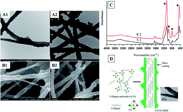
:![[thin space (1/6-em)]](https://www.rsc.org/images/entities/char_2009.gif) 1, a thick layer of dense silica is coated on the collagen fibrils, forming a core–shell structured Col–SA hybrid (Fig. 1A1, A2, B1 and B2). This result is in accordance with the reports by Eglin et al. and Ono et al., where hollow silica fibrils were produced with silica coated onto the surface of templating collagen fibrils.26,27 Some Col–SA fibrils also demonstrate a twisted structure, which is due to the presence of negatively charged silanol groups of silica coating on the surface of Col–SA hybrid (Fig. 1B1, B2, and C).9,28 When the SA/Col ratio is low (1
1, a thick layer of dense silica is coated on the collagen fibrils, forming a core–shell structured Col–SA hybrid (Fig. 1A1, A2, B1 and B2). This result is in accordance with the reports by Eglin et al. and Ono et al., where hollow silica fibrils were produced with silica coated onto the surface of templating collagen fibrils.26,27 Some Col–SA fibrils also demonstrate a twisted structure, which is due to the presence of negatively charged silanol groups of silica coating on the surface of Col–SA hybrid (Fig. 1B1, B2, and C).9,28 When the SA/Col ratio is low (1![[thin space (1/6-em)]](https://www.rsc.org/images/entities/char_2009.gif) :
:![[thin space (1/6-em)]](https://www.rsc.org/images/entities/char_2009.gif) 2, 1
2, 1![[thin space (1/6-em)]](https://www.rsc.org/images/entities/char_2009.gif) :
:![[thin space (1/6-em)]](https://www.rsc.org/images/entities/char_2009.gif) 1, or 2
1, or 2![[thin space (1/6-em)]](https://www.rsc.org/images/entities/char_2009.gif) :
:![[thin space (1/6-em)]](https://www.rsc.org/images/entities/char_2009.gif) 1), silicified collagen fibrils with core–shell structures are not formed (data not shown). When the SA/Col ratio is 3
1), silicified collagen fibrils with core–shell structures are not formed (data not shown). When the SA/Col ratio is 3![[thin space (1/6-em)]](https://www.rsc.org/images/entities/char_2009.gif) :
:![[thin space (1/6-em)]](https://www.rsc.org/images/entities/char_2009.gif) 1, the distance between two adjacent protrusions is 66.9 ± 5.8 nm (n = 30, Fig. 1A1 and B1), which is identical to the distance of the gap zone present in collagen fibrils (67 nm), indicating the templating function of collagen fibrils. Negatively charged silicic acid preferentially accumulates at sites of highly positively charged gap zone of collagen fibrils, leading to the formation of protrusions with a periodicity of about 67 nm (Fig. 1D).15,29 When the SA/Col ratio is 4
1, the distance between two adjacent protrusions is 66.9 ± 5.8 nm (n = 30, Fig. 1A1 and B1), which is identical to the distance of the gap zone present in collagen fibrils (67 nm), indicating the templating function of collagen fibrils. Negatively charged silicic acid preferentially accumulates at sites of highly positively charged gap zone of collagen fibrils, leading to the formation of protrusions with a periodicity of about 67 nm (Fig. 1D).15,29 When the SA/Col ratio is 4![[thin space (1/6-em)]](https://www.rsc.org/images/entities/char_2009.gif) :
:![[thin space (1/6-em)]](https://www.rsc.org/images/entities/char_2009.gif) 1, the shell thickness of the Col–SA core–shell structure increases, and the periodicity of the distinguished protrusions increases to 82.7 ± 21.0 nm (n = 40, Fig. 1A2 and B2). This is due to that with the increase of the SA/Col ratio, more and more silica precipitates on the surface of collagen fibrils, resulting in an increase in shell thickness and a decrease in electrostatic attraction between silicic acid and the gap zone of collagen fibrils. As a result, the surface of the coating was smoothened, and some adjacent protrusions fused together, leading to a longer distance between two adjacent protrusions (Fig. 1A2 and B2).
1, the shell thickness of the Col–SA core–shell structure increases, and the periodicity of the distinguished protrusions increases to 82.7 ± 21.0 nm (n = 40, Fig. 1A2 and B2). This is due to that with the increase of the SA/Col ratio, more and more silica precipitates on the surface of collagen fibrils, resulting in an increase in shell thickness and a decrease in electrostatic attraction between silicic acid and the gap zone of collagen fibrils. As a result, the surface of the coating was smoothened, and some adjacent protrusions fused together, leading to a longer distance between two adjacent protrusions (Fig. 1A2 and B2).
3.2. Col–PAH–SA fibrils
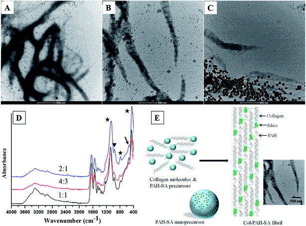
By controlling the silica precursors, twisted silicified collagen fibrils with bandings are produced (Fig. 2). A long-chain polyamine (poly(allylamine) hydrochloride (PAH, Mw = 15![[thin space (1/6-em)]](https://www.rsc.org/images/entities/char_2009.gif) 000 Da)) was used to stabilize silica by the formation of hydrogen bonds with silanol groups of silicic acid, which reduces the availability of silicic acid from forming polysilicic acid, and thereby leads to the formation of fluidic PAH–SA nanoprecursors.4 Rope-like, twisted silicified collagen fibrils are formed via a one-step approach by mixing PAH–SA precursors and collagen molecules (Fig. 2A–D). This result is in agreement with the reports by Desimone et al. and Heinemann et al.,9,28 where twisted fibrils were formed due to the presence of negatively charged silanol groups of silica (Fig. 2D). The average distances of two adjacent bandings for Col–PAH–SA fibrils are 143.3 ± 12.1 nm, 145.8 ± 7.5 nm, and 145.0 ± 11.8 nm for SA/Col ratio of 1
000 Da)) was used to stabilize silica by the formation of hydrogen bonds with silanol groups of silicic acid, which reduces the availability of silicic acid from forming polysilicic acid, and thereby leads to the formation of fluidic PAH–SA nanoprecursors.4 Rope-like, twisted silicified collagen fibrils are formed via a one-step approach by mixing PAH–SA precursors and collagen molecules (Fig. 2A–D). This result is in agreement with the reports by Desimone et al. and Heinemann et al.,9,28 where twisted fibrils were formed due to the presence of negatively charged silanol groups of silica (Fig. 2D). The average distances of two adjacent bandings for Col–PAH–SA fibrils are 143.3 ± 12.1 nm, 145.8 ± 7.5 nm, and 145.0 ± 11.8 nm for SA/Col ratio of 1![[thin space (1/6-em)]](https://www.rsc.org/images/entities/char_2009.gif) :
:![[thin space (1/6-em)]](https://www.rsc.org/images/entities/char_2009.gif) 1, 4
1, 4![[thin space (1/6-em)]](https://www.rsc.org/images/entities/char_2009.gif) :
:![[thin space (1/6-em)]](https://www.rsc.org/images/entities/char_2009.gif) 3 and 2
3 and 2![[thin space (1/6-em)]](https://www.rsc.org/images/entities/char_2009.gif) :
:![[thin space (1/6-em)]](https://www.rsc.org/images/entities/char_2009.gif) 1, respectively (Fig. 2A–C, n = 30). All the banding distances are significantly larger than that of the typical D-banding of collagen fibrils (67 nm). This may be due to that the amine groups of PAH in PAH–SA precursors interact with carboxyl groups of collagen molecules during the self-assembly of collagen fibrils, where PAH is inserted between two adjacent collagen molecules as a space linker, leading to a longer distance between adjacent gap zones (Fig. 2E). In PAH–SA precursors, silica is stabilized by PAH through ionic bonding and/or hydrogen bonding.4 Subsequently, PAH–SA precursors infiltrate into collagen fibrils along with PAH during the collagen fibril formation process. PAH is then separated from silicic acid, leading to the precipitation of silica at the C-terminus of collagen molecules, where the potential energy is the lowest.29 This explains why the banding in Fig. 2 is larger than that of the typical collagen D-banding because of the longer distance between adjacent gap zones of the fibrils and the precipitation of electron-dense minerals at the C-terminus of collagen molecules. The FTIR result also confirms the attachment of PAH onto collagen fibrils (Fig. 2D). The 528 cm−1 peak of FT-IR is assigned to the amine hydrogen bonding of PAH, indicating the attachment of PAH onto the silicified collagen fibrils (Fig. 2D).
1, respectively (Fig. 2A–C, n = 30). All the banding distances are significantly larger than that of the typical D-banding of collagen fibrils (67 nm). This may be due to that the amine groups of PAH in PAH–SA precursors interact with carboxyl groups of collagen molecules during the self-assembly of collagen fibrils, where PAH is inserted between two adjacent collagen molecules as a space linker, leading to a longer distance between adjacent gap zones (Fig. 2E). In PAH–SA precursors, silica is stabilized by PAH through ionic bonding and/or hydrogen bonding.4 Subsequently, PAH–SA precursors infiltrate into collagen fibrils along with PAH during the collagen fibril formation process. PAH is then separated from silicic acid, leading to the precipitation of silica at the C-terminus of collagen molecules, where the potential energy is the lowest.29 This explains why the banding in Fig. 2 is larger than that of the typical collagen D-banding because of the longer distance between adjacent gap zones of the fibrils and the precipitation of electron-dense minerals at the C-terminus of collagen molecules. The FTIR result also confirms the attachment of PAH onto collagen fibrils (Fig. 2D). The 528 cm−1 peak of FT-IR is assigned to the amine hydrogen bonding of PAH, indicating the attachment of PAH onto the silicified collagen fibrils (Fig. 2D).
3.3. Col–inSA fibrils
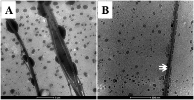
As shown in Fig. 3, intrafibrillar silicified collagen fibrils were produced using PAH and TPP as the positive and negative analogs of zwitterionic proteins, respectively. Compared to Col–PAH–SA fibrils, the morphology of collagen fibrils in the Col–inSA group exhibits a normal structure instead of twisted fibrils (Fig. 3, ESI, Fig. S1†).20 This may be due to the competition between TPP and PAH to interact with collagen molecules during the collagen self-assembly process. As a penta-anion, TPP has a stronger electrostatic attraction to the gap zone of collagen fibrils than PAH, leading to prohibition of further bonding of collagen molecules with PAH. Instead, fluidic PAH–SA precursors infiltrate into the collagen fibrils and precipitate within the gap zone (Fig. 5). Clear D-bandings are observed using TEM due to electron-dense silica precipitating within specific sites of collagen fibrils (Fig. 3 and 4). As shown in Fig. 3, the D-banding becomes more and more obvious with the increase of SA/Col ratios, and silica nanoparticles are also formed on the surface of collagen fibrils. Similar to silaffins and long-chain polyamines in diatoms, PAH and TPP have been used as respective positive and negative analogs of highly zwitterionic proteins to promote silica formation in vitro.30 In details, PAH mimics the positively charged groups of lysine residues in silaffins, while TPP mimics the negatively charged groups introduced by phosphorylation of serine residues.3,31 Similar to the mechanism of calcium phosphate intrafibrillar mineralization, TPP accumulates in the gap zone of collagen fibrils due to electrostatic attraction between the highly negatively charged TPP and the positively charged gap zone of collagen fibrils.20,29 TPP further attracts fluidic PAH–SA nanoprecursors to infiltrate into gap zones of collagen fibrils via electrostatic attraction and capillary action (Fig. 5 and 6).4,32,33 PAH promotes silica precipitation in the presence of TPP in the gap zone of collagen fibrils, leading to intrafibrillar silicification of collagen fibrils (Fig. 6).31,34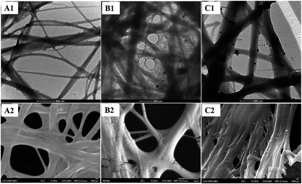 | ||
Fig. 3 TEM images (A1, B1, and C1) and FESEM images (A2, B2, and C2) of Col–inSA fibrils with different SA/Col ratios: 1![[thin space (1/6-em)]](https://www.rsc.org/images/entities/char_2009.gif) : :![[thin space (1/6-em)]](https://www.rsc.org/images/entities/char_2009.gif) 1 (A1, A2), 4 1 (A1, A2), 4![[thin space (1/6-em)]](https://www.rsc.org/images/entities/char_2009.gif) : :![[thin space (1/6-em)]](https://www.rsc.org/images/entities/char_2009.gif) 3 (B1, B2), and 2 3 (B1, B2), and 2![[thin space (1/6-em)]](https://www.rsc.org/images/entities/char_2009.gif) : :![[thin space (1/6-em)]](https://www.rsc.org/images/entities/char_2009.gif) 1 (C1, C2). 1 (C1, C2). | ||
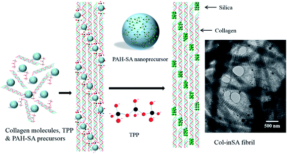 | ||
Fig. 6 Schematic illustration of the intrafibrillar mineralization process of Col–inSA fibrils. TEM image shows Col–inSA fibrils with a SA/Col ratio of 4![[thin space (1/6-em)]](https://www.rsc.org/images/entities/char_2009.gif) : :![[thin space (1/6-em)]](https://www.rsc.org/images/entities/char_2009.gif) 3. 3. | ||
3.4. Silicified collagen fibrils via a two-step approach
Moreover, silicification of collagen fibrils via a one-step approach was compared with a two-step approach. In a two-step approach, collagen fibrils were first self-assembled, and then silica precursors were added to the self-assembled collagen fibril suspension to enable the silicification of the precipitated collagen fibrils. Compared T–Col–SA fibrils with Col–SA fibrils at the same SA/Col ratio (SA/Col = 4![[thin space (1/6-em)]](https://www.rsc.org/images/entities/char_2009.gif) :
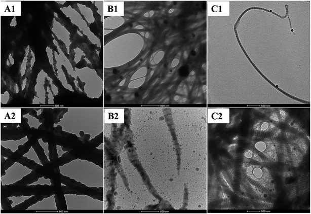
:![[thin space (1/6-em)]](https://www.rsc.org/images/entities/char_2009.gif) 1), silica particles rather than a continuous coating are deposited on the surface of collagen fibrils (Fig. 7A1 and A2). Silica particles may be absorbed onto the collagen fibrils due to electrostatic attraction, or through hydrogen bonding between silanol groups of silica and amine or hydroxyl groups of collagen.6 In the T–Col–PAH–SA fibrils, silica particles are only formed on the surface of collagen fibrils, while twisted silicified collagen fibrils are formed in Col–PAH–SA fibrils using one-step approach (Fig. 7B1 and B2, ESI, Fig. S1†). The comparison between T–Col–PAH–SA and Col–PAH–SA fibrils indicates that in the one-step approach PAH and silica are well integrated into the collagen self-assembly process and that the silicification and self-assembly of collagen fibrils occur simultaneously. In contrast, intrafibrillar silicification was observed in the Col–inSA fibrils formed via both the two-step and the one-step processes (Fig. 7C1 and C2). In both the two-step and the one-step approaches, highly negatively charged TPP accumulates in the positively charged gap zone of collagen fibrils through electrostatic attraction, which further attracts fluidic PAH–SA precursors to infiltrate into collagen fibrils.4,29,31 PAH and TPP function as the positive and negative analogs of zwitterionic proteins, respectively, which mediate the biosilicification process in nature systems. Similarly, the accumulation of PAH–SA and TPP in the gap zone of collagen fibrils enables the PAH–SA precursors to aggregate and form silica within collagen fibrils.3,13
1), silica particles rather than a continuous coating are deposited on the surface of collagen fibrils (Fig. 7A1 and A2). Silica particles may be absorbed onto the collagen fibrils due to electrostatic attraction, or through hydrogen bonding between silanol groups of silica and amine or hydroxyl groups of collagen.6 In the T–Col–PAH–SA fibrils, silica particles are only formed on the surface of collagen fibrils, while twisted silicified collagen fibrils are formed in Col–PAH–SA fibrils using one-step approach (Fig. 7B1 and B2, ESI, Fig. S1†). The comparison between T–Col–PAH–SA and Col–PAH–SA fibrils indicates that in the one-step approach PAH and silica are well integrated into the collagen self-assembly process and that the silicification and self-assembly of collagen fibrils occur simultaneously. In contrast, intrafibrillar silicification was observed in the Col–inSA fibrils formed via both the two-step and the one-step processes (Fig. 7C1 and C2). In both the two-step and the one-step approaches, highly negatively charged TPP accumulates in the positively charged gap zone of collagen fibrils through electrostatic attraction, which further attracts fluidic PAH–SA precursors to infiltrate into collagen fibrils.4,29,31 PAH and TPP function as the positive and negative analogs of zwitterionic proteins, respectively, which mediate the biosilicification process in nature systems. Similarly, the accumulation of PAH–SA and TPP in the gap zone of collagen fibrils enables the PAH–SA precursors to aggregate and form silica within collagen fibrils.3,13
Two kinds of polyanions were used: phosphate ions and TPP, but they have different functions. TPP inhibits the incorporation of PAH during the collagen self-assembly process (Fig. 7B2 and C2), and it also functions as a regulator to guide precise deposition of silica within collagen fibrils (Fig. 5B and 7B1 and C1). Phosphate ions, being one kind of kosmotrope anions, were used to favor collagen self-assembly.16 The comparison between T–Col–PAH–SA and T–Col–inSA fibrils indicates that, even though both phosphate ions and TPP induce phase separation of PAH–SA precursors,34,35 phosphate ions do not function as a regulator to attract PAH–SA to infiltrate into collagen fibrils (Fig. 7B1), but TPP does (Fig. 7C1).
3.5. In vitro cell culture
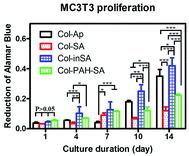
Different mineralized collagen fibrous membranes were tested for their ability to support cell growth in vitro. An osteoblastic cell line MC3T3-E1 was used. Collagen–apatite (Col–Ap) matrices have been widely used as scaffolds for bone tissue engineering, thus the Col–Ap fibrous membrane was used as the control.36–42 Cell proliferation and viability on different fibrous membranes were quantified using alamarBlue assay. The Col–inSA group supports a higher proliferation rate of MC3T3-E1 cells, especially at the late stage of incubation, compared with Col–Ap, Col–SA and Col–PAH–SA (Fig. 8). This result indicates that the intrafibrillar silicified collagen fibrous membrane has a better biological response to osteoblast cells compared with Col–Ap. It is well-established that silicon-induced cell responses are dose-dependent.43,44 As shown in the TEM and SEM images of Col–inSA fibrils (Fig. 3), silica is wrapped up by collagen fibrils, demonstrating dense and obvious D-banding structures, allowing gradual release of silicon.45 Therefore, intrafibrillar silicified collagen fibril can serve as a carrier and gradually release silicon ions from the collagen fibrils to positively impact cell activities instead of burst release causing negative cell responses.464. Conclusions
We have presented a one-step collagen self-assembly/silicification approach in preparation of intrafibrillar silicified collagen fibrils. Highly negatively charged TPP first accumulates in the positively charged gap zone of collagen fibrils due to electrostatic attraction, which further attracts positively charged fluidic PAH–SA precursors to enter the collagen fibrils. As the positive analog of the zwitterionic proteins in silicification, PAH promotes silica precipitation in the presence of negative analog, TPP. Thus the accumulation of PAH–SA and TPP in the gap zone of collagen fibrils facilitates the formation of silica within gap zone of collagen fibrils, resulting in intrafibrillar silicification. Moreover, the structure of the silicified collagen fibrils can be manipulated by varying silica precursors, polyanions and SA/Col ratios to produce silicified collagen fibrils with a core–shell, twisted, or banded structure. The intrafibrillar silicified collagen fibrils possess better cell compatibility compared with the collagen–apatite fibrils. Thus, this approach provides a facile method to produce intrafibrillar silicified collagen fibrils for biomedical applications.Disclosures
Dr. Wei has an ownership interest in OrteoPoniX LLC, which is developing and commercializing biomaterials for orthopedic applications.Acknowledgements
The authors would like to thank NSF grant (CBET-1347130) for its support.References
- C. C. Perry and T. Keeling-Tucker, J. Biol. Inorg Chem., 2000, 5, 537–550 CrossRef CAS PubMed.
- E. Beniash, Wiley Interdiscip. Rev.: Nanomed. Nanobiotechnol., 2011, 3, 47–69 CrossRef CAS PubMed.
- S. Wenzl, R. Hett, P. Richthammer and M. Sumper, Angew. Chem., 2008, 120, 1753–1756 CrossRef.
- L. Niu, K. Jiao, H. Ryou, A. Diogenes, C. K. Yiu, A. Mazzoni, J. Chen, D. D. Arola, K. M. Hargreaves and D. H. Pashley, Biomacromolecules, 2013, 14, 1661–1668 CrossRef CAS PubMed.
- A. Woesz, J. C. Weaver, M. Kazanci, Y. Dauphin, J. Aizenberg, D. E. Morse and P. Fratzl, J. Mater. Res., 2006, 21, 2068–2078 CrossRef CAS.
- H. Ehrlich, R. Deutzmann, E. Brunner, E. Cappellini, H. Koon, C. Solazzo, Y. Yang, D. Ashford, J. Thomas-Oates and M. Lubeck, Nat. Chem., 2010, 2, 1084–1088 CrossRef CAS PubMed.
- A. J. Mieszawska, N. Fourligas, I. Georgakoudi, N. M. Ouhib, D. J. Belton, C. C. Perry and D. L. Kaplan, Biomaterials, 2010, 31, 8902–8910 CrossRef CAS PubMed.
- W. Zhai, H. Lu, L. Chen, X. Lin, Y. Huang, K. Dai, K. Naoki, G. Chen and J. Chang, Acta Biomater., 2012, 8, 341–349 CrossRef CAS PubMed.
- M. F. Desimone, C. Hélary, G. Mosser, M. M. Giraud-Guille, J. Livage and T. Coradin, J. Mater. Chem., 2010, 20, 666–668 RSC.
- T. Delclos, C. Aimé, E. Pouget, A. Brizard, I. Huc, M. H. Delville and R. Oda, Nano Lett., 2008, 8, 1929–1935 CrossRef CAS PubMed.
- S. Heinemann, H. Ehrlich, T. Douglas, C. Heinemann, H. Worch, W. Schatton and T. Hanke, Biomacromolecules, 2007, 8, 3452–3457 CrossRef CAS PubMed.
- N. Kröger, S. Lorenz, E. Brunner and M. Sumper, Science, 2002, 298, 584–586 CrossRef PubMed.
- C. C. Lechner and C. F. Becker, Mar. Drugs, 2015, 13, 5297–5333 CrossRef CAS PubMed.
- M. F. Desimone, C. Hélary, I. B. Rietveld, I. Bataille, G. Mosser, M. M. Giraud-Guille, J. Livage and T. Coradin, Acta Biomater., 2010, 6, 3998–4004 CrossRef CAS PubMed.
- S. Heinemann, C. Heinemann, R. Bernhardt, A. Reinstorf, B. Nies, M. Meyer, H. Worch and T. Hanke, Acta Biomater., 2009, 5, 1979–1990 CrossRef CAS PubMed.
- S. Quignard, G. Copello, C. Aimé, I. Bataille, C. Hélary, M. F. Desimone and T. Coradin, Adv. Eng. Mater., 2012, 14, B51–B55 CrossRef.
- S. Heinemann, C. Heinemann, H. Ehrlich, M. Meyer, H. Baltzer, H. Worch and T. Hanke, Adv. Eng. Mater., 2007, 9, 1061–1068 CrossRef.
- S. Heinemann, H. Ehrlich, C. Knieb and T. Hanke, Int. J. Mater. Res., 2007, 98, 603–608 CrossRef CAS.
- K. Spinde, M. Kammer, K. Freyer, H. Ehrlich, J. N. Vournakis and E. Brunner, Chem. Mater., 2011, 23, 2973–2978 CrossRef CAS.
- C. Hu, L. Zhang and M. Wei, ACS Biomater. Sci. Eng., 2015, 1, 669–676 CrossRef CAS.
- C. Hu, M. Zilm and M. Wei, J. Biomed. Mater. Res., Part A, 2016, 104, 1153–1161 CrossRef CAS PubMed.
- N. Rajan, J. Habermehl, M. F. Coté, C. J. Doillon and D. Mantovani, Nat. Protoc., 2006, 1, 2753–2758 CrossRef CAS PubMed.
- L. Niu, K. Jiao, Y. Qi, C. K. Yiu, H. Ryou, D. D. Arola, J. Chen, L. Breschi, D. H. Pashley and F. R. Tay, Angew. Chem., 2011, 123, 11892–11895 CrossRef.
- L. Niu, K. Jiao, H. Ryou, C. K. Yiu, J. Chen, L. Breschi, D. D. Arola, D. H. Pashley and F. R. Tay, Angew. Chem., 2013, 125, 5874–5878 CrossRef.
- D. A. Cisneros, J. Friedrichs, A. Taubenberger, C. M. Franz and D. J. Muller, Small, 2007, 3, 956–963 CrossRef CAS PubMed.
- Y. Ono, Y. Kanekiyo, K. Inoue, J. Hojo, M. Nango and S. Shinkai, Chem. Lett., 1999, 475–476 CrossRef CAS.
- D. Eglin, G. Mosser, M.-M. Giraud-Guille, J. Livage and T. Coradin, Soft Matter, 2005, 1, 129–131 RSC.
- S. Heinemann, C. Heinemann, M. Jager, J. Neunzehn, H. Wiesmann and T. Hanke, ACS Appl. Mater. Interfaces, 2011, 3, 4323–4331 CAS.
- F. Nudelman, K. Pieterse, A. George, P. H. Bomans, H. Friedrich, L. J. Brylka, P. A. Hilbers, G. de With and N. A. Sommerdijk, Nat. Mater., 2010, 9, 1004–1009 CrossRef CAS PubMed.
- N. Kröger, R. Deutzmann and M. Sumper, Science, 1999, 286, 1129–1132 CrossRef.
- N. Li, L. Niu, Y. Qi, C. K. Yiu, H. Ryou, D. D. Arola, J. Chen, D. H. Pashley and F. R. Tay, Biomaterials, 2011, 32, 8743–8752 CrossRef CAS PubMed.
- Y. Liu, Y. K. Kim, L. Dai, N. Li, S. O. Khan, D. H. Pashley and F. R. Tay, Biomaterials, 2011, 32, 1291–1300 CrossRef CAS PubMed.
- Y. K. Kim, L. Gu, T. E. Bryan, J. R. Kim, L. Chen, Y. Liu, J. C. Yoon, L. Breschi, D. H. Pashley and F. R. Tay, Biomaterials, 2010, 31, 6618–6627 CrossRef CAS PubMed.
- E. Brunner, K. Lutz and M. Sumper, Phys. Chem. Chem. Phys., 2004, 6, 854–857 RSC.
- J. Fothergill, M. Li, S. A. Davis, J. A. Cunningham and S. Mann, Langmuir, 2014, 30, 14591–14596 CrossRef CAS PubMed.
- Z. Xia and M. Wei, J. Biomater. Tissue Eng., 2013, 3, 369–384 CrossRef CAS.
- Z. Xia, X. Yu, X. Jiang, H. D. Brody, D. W. Rowe and M. Wei, Acta Biomater., 2013, 9, 7308–7319 CrossRef CAS PubMed.
- Y. Pek, S. Gao, M. M. Arshad, K. Leck and J. Y. Ying, Biomaterials, 2008, 29, 4300–4305 CrossRef CAS PubMed.
- M. M. Villa, L. Wang, J. Huang, D. W. Rowe and M. Wei, J. Biomed. Mater. Res., Part B, 2015, 103, 243–253 CrossRef PubMed.
- X. Yu, Z. Xia, L. Wang, F. Peng, X. Jiang, J. Huang, D. Rowe and M. Wei, J. Mater. Chem., 2012, 22, 9721–9730 RSC.
- X. Yu, L. Wang, F. Peng, X. Jiang, Z. Xia, J. Huang, D. Rowe and M. Wei, J. Tissue Eng. Regener. Med., 2013, 7, 974–983 CrossRef CAS PubMed.
- M. M. Villa, L. Wang, J. Huang, D. W. Rowe and M. Wei, J. Biomed. Mater. Res., Part B, 2015, 103, 243–253 CrossRef PubMed.
- H. A. Santos, J. Riikonen, J. Salonen, E. Mäkilä, T. Heikkilä, T. Laaksonen, L. Peltonen, V. P. Lehto and J. Hirvonen, Acta Biomater., 2010, 6, 2721–2731 CrossRef CAS PubMed.
- E. A. Bortoluzzi, L. Niu, C. D. Palani, A. R. El-Awady, B. D. Hammond, D. Pei, F. Tian, C. W. Cutler, D. H. Pashley and F. R. Tay, Dent. Mater., 2015, 31, 1510–1522 CrossRef CAS PubMed.
- L. Niu, K. Jiao, Y. Qi, S. Nikonov, C. K. Yiu, D. D. Arola, S. Gong, A. El-Marakby, M. R. Carrilho and M. W. Hamrick, FASEB J., 2012, 26, 4517–4529 CrossRef CAS PubMed.
- S. Bhattacharjee, I. M. Rietjens, M. P. Singh, T. M. Atkins, T. K. Purkait, Z. Xu, S. Regli, A. Shukaliak, R. J. Clark and B. S. Mitchell, Nanoscale, 2013, 5, 4870–4883 RSC.
Footnote |
| † Electronic supplementary information (ESI) available. See DOI: 10.1039/c7ra02935g |
| This journal is © The Royal Society of Chemistry 2017 |

