 Open Access Article
Creative Commons Attribution 3.0 Unported Licence
Enhancement of the near-infrared emission of Ce3+–Yb3+ co-doped Y3Al5O12 phosphors by doping Bi3+ ions
K. Santhosh Kumar a,
Chaogang Lou
 *a,
A. Gowri Manohari
 b,
Cao Huihuia and
Didier Pribata
aSchool of Electronic Science and Engineering, Southeast University, Nanjing 210096, Jiangsu Province, People's Republic of China. E-mail: lcg@seu.edu.cn
bSchool of Biological Sciences and Medical Engineering, Southeast University, Nanjing 210096, Jiangsu Province, People's Republic of China
First published on 8th May 2017
Abstract
Ce3+–Yb3+ co-doped Y3Al5O12 phosphors are one of most the potential candidates of down-conversion materials for photovoltaic cells. To improve the near-infrared emission from Yb3+ ions, Bi3+ ions were introduced into the phosphors. The experimental results showed that the intensity of Yb3+ emission was greatly enhanced after doping Bi3+ ions into the phosphors. This may be attributed to an additional pathway via Bi3+ ions for the energy transfer from Ce3+ to Yb3+. Different from the co-doped phosphors, where the energy of Ce3+ ions was transferred only to Yb3+ ions, in Bi3+–Ce3+–Yb3+ tri-doped phosphors, the energy of Ce3+ ions could be transferred not only to Yb3+ ions but also to Bi3+ ions. Then, Bi3+ ions transferred part of the energy to Yb3+ ions. This enabled Yb3+ ions to obtain more energy and enhance their near-infrared emission.
Introduction
Crystalline silicon (c-Si) solar cells have quickly developed over the past few decades because of the huge demand for clean energy.1,2 One of the factors limiting the conversion efficiency of the solar cells is the spectral mismatch between the solar spectrum and the energy band gap of silicon.1,3 This results in the problems that the photons with energies lower than the band gap cannot be absorbed, and the higher-energy photons lose the excess of the energy in the cells through thermalization. A possible solution to the latter problem is to cut a higher-energy photon into two or more near-infrared (NIR) photons, which can still be absorbed by the cells.4A down-conversion process is considered to be a promising way to enhance the efficiency of solar cells because it provides the possibility of converting one higher-energy photon into two or more lower-energy photons.5,6 It has been reported that by this way, the maximum conversion efficiency of the c-Si solar cells could be greatly improved.4 For this reason, down-conversion materials have attracted significant attention in recent years.7–10
Rare earth (RE) phosphors have been considered as one of the potential candidates of down-conversion materials because RE ions have rich energy level structures, which allow efficient spectral conversion.11 Among RE ions, Yb3+ ions are desirable due to their high luminescence quantum efficiency and emitted wavelength (950–1050 nm), which is close to the band gap of Si.12 To date, a number of studies have been performed on the RE3+–Yb3+ co-doped phosphors, in which RE3+ ions (RE = Tb, Tm, Pr, Er, Nd, and Ho) were used as sensitizers and Yb3+ ions were used as activators.13–17 However, the weak and narrow absorption of these sensitizers prevented them from being applied as photovoltaic down-conversion materials.18
On the other hand, some rare earth ions, such as Ce3+ and Eu2+, with broader absorption have also been used as sensitizers in the phosphors.19–22 Because of the success of Ce3+-doped Y3Al5O12 (YAG) phosphors in semiconductor lighting, Ce3+–Yb3+ co-doped Y3Al5O12 phosphors have naturally been considered as potential down-conversion materials.19 Although several attempts have been made in this regard, the efficiency of the energy transfer from Ce3+ to Yb3+ in the phosphors is still not satisfactory due to the complicated mechanism.23,24
In this study, Bi3+ ions were introduced into Ce3+–Yb3+ co-doped YAG phosphors to improve the energy transfer from Ce3+ to Yb3+. Their influences on the emission of Yb3+ and the energy transfers between Bi3+, Ce3+, and Yb3+ were studied.
Experimental
Bi3+–Ce3+–Yb3+ tri-doped YAG phosphors were prepared by a traditional solid–state reaction method. The powders of Y2O3 (99.99%), Al2O3 (99.99%), Bi2O3 (99%), Ce2O3 (99.99%), and Yb2O3 (99.99%) were stoichiometrically mixed. Then, the mixture was transferred into an alumina crucible and heated at 1600 °C for 6 h in an N2 + H2 atmosphere in a chamber furnace. The samples were cooled down to room temperature and were ground again. The excitation and emission spectra of the phosphors were obtained using Ocean Optics MAYA 2000PRO. Fluorescence lifetimes were measured using a FM-4P-TCSPC spectrofluorometer (Horiba Jobin Yvon). All the measurements were carried out at room temperature.Results and discussion
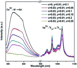
Fig. 1 shows the emission spectra of Y3−x−y−zAl5O12: xBi3+yCe3+zYb3+ (x = 0, 0.03; y = 0.01; and z = 0.05, 0.1, 0.15, 0.2, and 0.25) phosphors under an excitation of 455 nm. It can be seen that the emissions from Ce3+ and Yb3+ vary with the Yb3+ concentration. When Yb3+ concentration was low (z = 0.05, 0.1, and 0.15), the NIR emission from Yb3+ ions increased with an increase in the Yb3+ concentration. This occurred because the energy transferred to Yb3+ from Ce3+ increased with the concentration of Yb3+. This is also the reason why the emission from Ce3+ ions decreased with the increasing Yb3+ concentration. When the Yb3+ concentration continued to increase to z = 0.2 and 0.25, although the energy from Ce3+ to Yb3+ increased, the Yb3+ emission became weaker due to the concentration quenching effect of Yb3+.25The most desirable result, as shown in Fig. 1, is that in the cases of x = 0.03, y = 0.01, and z = 0.05, 0.10, and 0.15, the intensity of NIR emission from Yb3+ ions in Bi3+–Ce3+–Yb3+ tri-doped phosphors was stronger than that in Ce3+–Yb3+ co-doped phosphors (x = 0, y = 0.01, and z = 0.1). Fig. 2 shows the intensities of the emissions at 1027 nm from the phosphors with different chemical compositions. Although the NIR emission of the tri-doped samples when z = 0.2 and 0.25 was weaker than that of the co-doped phosphors due to the concentration quenching effect of Yb3+, the stronger emission of the tri-doped phosphors when z = 0.05, 0.10, and 0.15 indicated that the introduction of Bi3+ ions could improve the emission from Yb3+ ions.
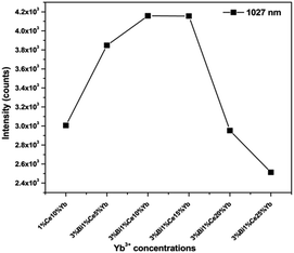 | ||
| Fig. 2 Emission intensities of Yb3+ at 1027 nm from different YAG phosphors under the excitation of 455 nm. | ||
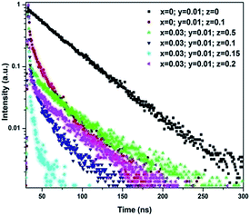
Because Yb3+ ions cannot absorb the photons with a wavelength of 455 nm, their emission resulted from the energy transfer inside the phosphors. To explain the curves shown in Fig. 1 and 2, it is necessary to clarify the energy transfers between Bi3+, Ce3+, and Yb3+ ions in the tri-doped phosphors. Fig. 3 shows the luminescence decay curves of Ce3+ (monitored at 560 nm) in singly Ce3+-doped (x = 0, y = 0.01, and z = 0), Ce3+–Yb3+ co-doped (x = 0, y = 0.01, and z = 0.1), and Bi3+–Ce3+–Yb3+ tri-doped (x = 0.03, y = 0.01, and z = 0.05, 0.1, 0.15, and 0.2) YAG phosphors under the excitation of 455 nm. Clearly, the emission from Ce3+ in the tri-doped phosphors decayed faster than that in the Ce3+–Yb3+ co-doped phosphors. Because the tri-doped samples have Bi3+ ions, whereas the co-doped sample does not, the faster decay of the emission from Ce3+ in the tri-doped phosphors might be attributed to the energy transfer from Ce3+ ions to Bi3+ ions.
To understand the energy transfer in detail, the efficiency of the energy transfers from Ce3+ to other ions was calculated. According to previous studies,26,27 the energy transfer efficiency ηETE can be estimated using the following equation:
 | (1) |
 | (2) |
From the decay curves shown in Fig. 3, the fluorescence lifetimes of Ce3+ were calculated to be 15.3 ns in the tri-doped phosphors (x = 0.03, y = 0.01, and z = 0.1), 24.3 ns in Ce3+–Yb3+ co-doped phosphors (x = 0, y = 0.01, and z = 0.1), and 65.7 ns in the singly Ce3+-doped phosphors (x = 0, y = 0.01, and z = 0). The energy transfer efficiency calculated from the decay curve of Ce3+ in the tri-doped phosphors was about 76.78%, whereas the energy transfer efficiency in the co-doped phosphors was 63.02%.
The reasonable explanation for the different energy transfer efficiencies in the two types of phosphors was that in the co-doped phosphors, there was only one pathway for the energy transfer. The energy was transferred from Ce3+ to Yb3+, whereas in the tri-doped phosphors, the energy of Ce3+ could be transferred via two pathways. One pathway was from Ce3+ to Yb3+ and the other was from Ce3+ to Bi3+ to Yb3+.
The evidence for the energy transfer from Ce3+ to Bi3+ can be found in Fig. 4, which shows the decay curves of Ce3+ singly doped and Ce3+–Bi3+ co-doped YAG phosphors. Under the excitation of 455 nm, the emission of Ce3+ in the singly doped phosphors showed nearly a single exponential decay with a fluorescence lifetime of 65.7 ns, whereas in Ce3+–Bi3+ co-doped samples, the fluorescence lifetime decreased to 56.3 ns. The calculated energy transfer efficiency was 14.31%. This indicated that the energy transfer from Ce3+ to Bi3+ was possible inside the phosphors.
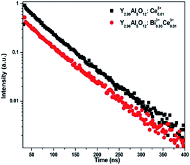 | ||
| Fig. 4 The decay curves of Ce3+ emission at 560 nm for Ce3+ singly doped and Ce3+–Bi3+ co-doped YAG phosphors under an excitation of 455 nm. | ||
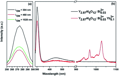
After Bi3+ ions received energy from Ce3+, the energy could be partly transferred to Yb3+. To prove this, the Bi3+ singly doped and Bi3+–Yb3+ co-doped YAG phosphors were prepared. The evidence of the energy transfer from Bi3+ to Yb3+ can be found in Fig. 5 and 6. From Fig. 5(a), it can be seen that an excitation band is centered at 275 nm due to the transition of Bi3+: 1S0 → 1P1, 3P1 detected by monitoring at 304 and 460 nm. Moreover, a similar excitation spectrum was also obtained for the transition of Yb3+: 2F5/2 → 2F7/2 at the monitoring wavelength of 1028 nm. The similarity in the shape of both excitation spectra can be considered as a direct evidence for the energy transfer (ET) from Bi3+ to Yb3+. The emission spectra of singly doped Bi3+ and co-doped Bi3+–Yb3+ phosphors under the excitation of 275 nm are shown in Fig. 5(b). The singly doped Bi3+ spectrum depicts two emission peaks centered at 304 nm and 460 nm. In the co-doped Bi3+–Yb3+ samples, apart from the emissions of Bi3+ ions, a strong NIR emission of Yb3+ could also be obtained at 1028 nm, which was accompanied by several weak shoulder peaks due to the transitions among different stark levels of 2Fj (j = 5/2, 7/2) in Yb3+. Because Yb3+ ions cannot absorb the photons of 275 nm, their NIR emission indicates an energy transfer from Bi3+ to Yb3+.
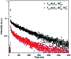 | ||
| Fig. 6 The decay curves of Bi3+ emission at 304 nm for Bi3+ singly doped and Bi3+–Yb3+ co-doped YAG phosphors under an excitation of 275 nm. | ||
Fig. 6 shows the decay curves of singly Bi3+ doped and Bi3+–Yb3+ co-doped phosphors under an excitation of 275 nm. The faster decay of Bi3+ emission in the co-doped samples also proved the energy transfer from Bi3+ to Yb3+. From Fig. 6, the fluorescence lifetime of Bi3+ was calculated as 768 ns in the singly doped phosphors, decreased to 576 ns after Yb3+ ions were introduced. The calculated energy transfer efficiency from Bi3+ to Yb3+ was 24.95%.
In principle, the amount of the energy transferred from Ce3+ to Yb3+ in the tri-doped phosphors should be close to that in Ce3+–Yb3+ co-doped phosphors because these two types of phosphors have the same concentrations of Ce3+ and Yb3+.29 This should result in similar intensities in the NIR emission from Yb3+. However, in the tri-doped phosphors, besides transferring energy to Yb3+, Ce3+ could also transfer energy to Bi3+. The energy transferred to Bi3+ was then partly transferred to Yb3+; thus, Yb3+ ions obtained more energy in the tri-doped phosphors than in the co-doped phosphors. This is why the NIR emission from Yb3+ in the tri-doped phosphors was stronger than that in the co-doped phosphors, as shown in Fig. 1.
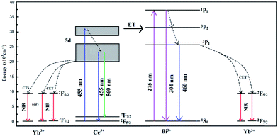
Based on the abovementioned results, the possible energy transfer processes were analyzed, and the schematic energy level diagram is shown in Fig. 7. In the Ce3+–Bi3+–Yb3+ tri-doped phosphors, the possible energy transfer processes takes place in four ways: Ce3+ → Yb3+, Ce3+ → Bi3+, Bi3+ → Yb3+, and Ce3+ → Bi3+ → Yb3+. For the first energy transfer of Ce3+ → Yb3+, the energy of the 5d → 4f transition of Ce3+ was approximately twice as high as the energy of the 2F5/2 → 2F7/2 transition of Yb3+. The energy of Ce3+ transfered to Yb3+ by two possible ways. One way was that one UV/blue photon was converted into two NIR photons by a cooperative energy transfer (CET),30 other was that the energy transferred from Ce3+ to Yb3+ via a charge transfer state (CTS).24,31,32 To date, both CTS and CET models lack direct experimental evidence and are still in dispute. For the second energy transfer process of Ce3+ → Bi3+, the mechanism was more complicated. The electrons of the excited 5d state of Ce3+ ions could transit to the 3P2 state of Bi3+ ions because these two energy levels were close to each other. On the other hand, after Bi3+ ions obtain the energy, part of electrons of the excited 3P2 state of Bi3+ ions could transit back to 5d state of Ce3+ ions, and rest of the electrons transited to 2F5/2 level of Yb3+ or the ground state 1S0 of Bi3+. For the third energy transfer of Bi3+ → Yb3+, the energy level 3P1 of Bi3+ was approximately twice as high as the energy difference between the 2F5/2 and 2F7/2 levels of Yb3+. The energy of Bi3+ might directly transfer to nearby Yb3+ ions via CET.33 On the basis of the abovementioned ET processes, the fourth energy transfer of Ce3+ → Bi3+ → Yb3+ is easy to be understood. At an excitation of 455 nm, after Ce3+ ions were excited to the 5d state, part of the excited electrons transited to the 2F5/2 and 2F7/2 states of Ce3+, and part of the excited electrons transited to the 3P states of Bi3+ ions and then Bi3+ transferred energy to Yb3+.
According to the above mentioned ET processes, Bi3+ ions, as the new pathway for the energy transfer, played an important role in enhancing the NIR emission of Ce3+–Bi3+–Yb3+ tri-doped Y3Al5O12 phosphors.
Note that the enhancement of NIR emission from Yb3+ by introducing Bi3+ ions into Ce3+–Yb3+ co-doped phosphors does not mean that other ions have similar effects. We attempted to dope Tb3+ ions into Ce3+–Yb3+ co-doped phosphors, but did not observe an improvement in Yb3+ emission. Therefore, clarifying the mechanism of the energy transfer in the Bi3+–Ce3+–Yb3+ YAG phosphors is important to further improve the NIR emission in future studies.
Conclusions
The NIR emission from Yb3+ in Ce3+–Yb3+ co-doped Y3Al5O12 phosphors under an excitation of 455 nm was improved by introducing Bi3+ ions. This was because Ce3+ ions transferred energy to Bi3+ ions in addition to Yb3+ ions in Bi3+–Ce3+–Yb3+ tri-doped YAG phosphors. Then, the energy of Bi3+ ions was partly transferred to Yb3+ ions. This made Yb3+ ions obtain more energy in the tri-doped phosphors than in the co-doped phosphors and resulted in more NIR emission.Acknowledgements
The authors thank the support provided by the Natural Science Foundation of Jiangsu (Grant No. BK2011033), Jiangsu Planned Projects for Postdoctoral Research Funds (Grant No. 1501042B) and the Primary Research & Development Plan of Jiangsu Province (Grant No. BE2016175). The authors also thank Dr Xuefeng Ge at the Center for Analysis and Testing of Nanjing Normal University for his help in characterizing the decay curves of the phosphors.References
- B. M. van der Ende, L. Aarts and A. Meijerink, Adv. Mater., 2009, 21, 3073 CrossRef CAS.
- B. Fan, C. Chlique, O. Merdrignac-Conanec, X. H. Zhang and X. P. Fan, J. Phys. Chem. C, 2012, 116, 11652 CAS.
- B. van der Zwaan and A. Rabl, Sol. Energy, 2003, 74, 19 CrossRef.
- T. Trupke, M. A. Green and P. Wurfel, J. Appl. Phys., 2002, 92, 1668 CrossRef CAS.
- W. Shockley and H. J. Queisser, J. Appl. Phys., 1961, 32, 510 CrossRef CAS.
- B. S. Richards, Sol. Energy Mater. Sol. Cells, 2006, 90, 1189 CrossRef CAS.
- D. C. Yu, S. Ye, M. Y. Peng, Q. Y. Zhang and L. Wondraczek, Appl. Phys. Lett., 2012, 100, 191911 CrossRef.
- X. Wei, S. Huang, Y. Chen, C. Guo, M. Yin and W. Xu, J. Appl. Phys., 2010, 107, 103107 CrossRef.
- J. J. Eilers, D. Biner, J. T. van Wijngaarden, K. Kramer, H. U. Gudel and A. Meijerink, Appl. Phys. Lett., 2010, 96, 151106 CrossRef.
- H. Zhang, J. Chen and H. Guo, J. Rare Earths, 2011, 29, 822 CrossRef CAS.
- R. Zhou, Y. Kou, X. Wei, C. Duan, Y. Chen and M. Yin, Appl. Phys. B, 2012, 107, 483 CrossRef CAS.
- Q. Y. Zhang and X. Y. Huang, Prog. Mater. Sci., 2010, 55, 353 CrossRef CAS.
- P. Vergeer, T. J. H. Vlugt, M. H. F. Kox, M. I. den Hertog, J. P. J. M. van der Eerden and A. Meijerink, Phys. Rev. B: Condens. Matter Mater. Phys., 2005, 71, 014119 CrossRef.
- Q. Y. Zhang, C. H. Yang and Y. X. Pan, Appl. Phys. Lett., 2007, 90, 021107 CrossRef.
- D. Q. Chen, Y. S. Wang, Y. L. Yu, P. Huang and F. Y. Weng, Opt. Lett., 2008, 33, 1884 CrossRef CAS PubMed.
- B. M. van der Ende, L. Aarts and A. Meijerink, Phys. Chem. Chem. Phys., 2009, 11, 11081 RSC.
- J. M. Meijerk, L. Aarts, B. M. van der Ende, T. J. H. Vlugt and A. Meijerink, Phys. Rev. B: Condens. Matter Mater. Phys., 2010, 81, 035107 CrossRef.
- J. Ueda and S. Tanabe, J. Appl. Phys., 2009, 106, 043101 CrossRef.
- Y. Li, J. Wang, W. Zhou, G. Zhang, Y. Chen and Q. Su, Appl. Phys. Express, 2013, 6, 082301 CrossRef.
- X. Liu, Y. Teng, Y. Zhuang, J. Xie, Y. Qiao, G. Dong, D. Chen and J. Qiu, Opt. Lett., 2009, 34, 3565 CrossRef CAS PubMed.
- J. Sun, Y. Sun, J. Zeng and H. Du, Opt. Mater., 2013, 35, 1276 CrossRef CAS.
- G. Gao and L. Wondraczek, J. Mater. Chem. C, 2013, 1, 1952 RSC.
- E. van der Kolk, O. M. Ten Kate, J. W. Wiegman, D. Biner and K. W. Kramer, Opt. Mater., 2011, 33, 1024 CrossRef CAS.
- D. C. Yu, F. T. Rabouw, W. Q. Boon, T. Kieboom, S. Ye, Q. Y. Zhang and A. Meijerink, Phys. Rev. B: Condens. Matter Mater. Phys., 2014, 90, 165126 CrossRef.
- J. Liao, Y. Lin, Y. Chen, Z. Luo, E. Ma, X. Gong, Q. Tan and Y. Huang, J. Opt. Soc. Am. B, 2006, 23, 2572 CrossRef CAS.
- P. I. Paulose, G. Jose, V. Thomas, N. V. Unnikrishnan and M. K. R. Warrier, J. Phys. Chem. Solids, 2003, 64, 841 CrossRef CAS.
- Q. Y. Zhang, C. H. Yang, Z. H. Jiang and X. H. Ji, Appl. Phys. Lett., 2007, 90, 061914 CrossRef.
- A. Speghini, M. Bettinelli, P. Riello, S. Bucella and A. Benedetti, J. Mater. Res., 2005, 20, 2780 CrossRef CAS.
- L.-M. Shao and X.-P. Jing, ECS J. Solid State Sci. Technol., 2012, 1, R22 CrossRef CAS.
- H. Lin, S. M. Zhou, H. Teng, Y. K. Li, W. J. Li, X. R. Hou and T. T. Jia, J. Appl. Phys., 2010, 107, 043107 CrossRef.
- J. Zhao, C. Guo, T. Li, D. Songa and X. Su, Phys. Chem. Chem. Phys., 2015, 17, 26330 RSC.
- J. Zhao, C. Guo and T. Li, RSC Adv., 2015, 5, 28299 RSC.
- C. Parthasaradhi Reddy, V. Naresh, B. Chandra Babu and S. Buddhudu, Adv. Mater. Phys. Chem., 2014, 4, 165 CrossRef.
| This journal is © The Royal Society of Chemistry 2017 |

