DOI:
10.1039/C7RA02980B
(Paper)
RSC Adv., 2017,
7, 25237-25243
Large-scalable RTCVD Graphene/PEDOT:PSS hybrid conductive film for application in transparent and flexible thermoelectric nanogenerators†
Received
12th March 2017
, Accepted 12th April 2017
First published on 10th May 2017
Abstract
Poly(3,4-ethyldioxythiophene):poly(styrene sulfonate) (PEDOT:PSS), as an thermoelectric(TE) material, exhibits a high electrical conductivity and ZT value (10−1–100). Nevertheless, a low thermovoltage of the organic thermoelectric materials must be overcome, in comparison to that of semi metals. Recently, to address these challenges, several researchers have investigated PEDOT:PSS/carbon material composites. Herein, a transparent and flexible hybrid film made up of rapid thermal chemical vapor deposition (RTCVD) graphene and PEDOT:PSS results in enhanced TE performance. The PEDOT:PSS was synthesized by oxidative polymerization, and the hybrid process of the graphene film and PEDOT:PSS film was conducted using the layer-by-layer method. The results of AFM and Raman spectroscopy revealed that the synergistic effect through composite films improved the electrical properties. The maximum electrical conductivity and power factor of the RTCVD graphene/PEDOT:PSS (RCG/P) hybrid film were 1096 S cm−1 and 57.9 μW m−1 K−2, respectively. In addition, the RCG/P hybrid film exhibited excellent mechanical flexibility and stability.
Introduction
A flexible thermoelectric (TE) generator is an important energy harvesting system for convenient electronics. In terms of flexibility, organic materials are often compared with inorganic materials because they can undergo solution processing.1,2 In recent years, poly(3,4-ethyldioxythiophene):poly(styrene sulfonate), which is a representative conducting polymer, has been actively investigated, amongst other organic thermoelectric materials such as polyacetylene (PA), polyaniline (PANI), polypyrrole (PPy) and polythiophene (PT).3–9 The PEDOT:PSS has attracted significant attention due to its excellent electrical conductivity, optical properties, and water solubility. Furthermore, when it is treated with some organic solvents such as dimethyl sulfoxide (DMSO), or ethylene glycol (EG), its electrical conductivity dramatically increases due to a conformational change in the PEDOT chains.10,11 Despite PEDOT:PSS having a high electrical conductivity, facile processing, cheap cost, and low thermal conductivity, its TE figure of merit (ZT) is smaller than that of inorganic materials such as bismuth telluride (Bi2Te3), antimony telluride (Sb2Te3), and silicon (Si). The ZT value of inorganic materials can be improved by controlling their nano-structure.12–14 However, the high thermal conductivity, high cost, difficulty of processing, and toxicity of inorganic materials are problems that remain to be solved. To overcome these limitations, several researchers have studied composites made up of conducting polymers and inorganic or carbon-based materials.15–20
In the case of conductive polymer/carbon-based material composites, CNTs (carbon nanotubes), or graphene, can interact with the backbone of the polymer due to their delocalized π-electrons. The π–π stacking interaction between carbon-based materials and polymers results in an improved electrical conductivity, chemical stability, and thermoelectric performance. A composite processing technique, where the carbon-based materials are dispersed in the organic polymer solution, is conducted by blending the different contents. In addition, composites made through the in situ polymerization of the monomers in the presence of the carbon-based materials have been vigorously investigated. These composites show a very low thermal conductivity because the CNTs, or graphene sheets, are covered with the organic polymer. Therefore, conductive polymer/carbon-based material composites are promising TE materials. In a previous study, we demonstrated that the hybridization of one-dimensional CNTs and two-dimensional graphene platelets with PEDOT:PSS, using in situ polymerization, resulted in remarkably enhanced TE properties.21 In this study, we investigated a flexible and transparent film using RTCVD graphene coated with a PEDOT:PSS conducting layer. The RTCVD graphene was transferred onto a PET substrate. By introducing the PEDOT:PSS conducting polymer, the defects on the graphene film surface were covered well, and its electrical properties were improved without a loss in transmittance. The results show the potential of a transparent film, which inorganic composites could not overcome for application in the TE devices. In addition, the π–π stacking interaction between graphene and the backbone of PEDOT:PSS results in a flexible film with enhanced electrical and thermoelectric properties, and an excellent bending stability, in comparison with untreated graphene film.
Experimental
Materials
Sodium persulfate (Na2S2O8, ≥99.0%), iron(III) sulfate [Fe2(SO4)3, 97%], 3,4-ethylenedioxythiphene (EDOT), poly(sodium 4-styrenesulfonate) (PSS), and isopropyl alcohol (IPA), dimethyl sulfoxide (DMSO), the cation exchange resin, and anion exchange resin were purchased from Sigma Aldrich Co., Yongin-Si, Gyeonggi-do, Korea. The RTCVD graphene22 was provided by HAESUNGDS Co., LTD, and the graphene films were transferred onto a PET substrate.
Preparation of PEDOT:PSS
The polymerization of PEDOT in the presence of PSS was similar to that in our previous report.22 The aqueous dispersion of PSS was bubbled with inert argon gas (99.999%) for 60 min at a rate of 3 L min−1 in order to remove the dissolved oxygen from the aqueous medium and to minimize the over-oxidation of the EDOT units during polymerization. The EDOT monomer (5.01 g) was then added and mixed using a mechanical stirrer for 30 min in the dispersion. The oxidizing reagents iron(III) sulfate (0.20 g, 5.01 × 10⁻⁴ mol) and sodium persulfate (8.02 g, 3.45 × 10⁻² mol) were dissolved in 50 mL of deionized water. The solutions were then added to the EDOT and PSS/carbon material dispersion to facilitate the oxidative polymerization of EDOT in the presence of PSS. The polymerization was carried out for 48 h at 5 °C with bubbling of inert argon (Ar) gas. After the polymerization, the product was blended with 300 mL of a mixture of bead-type cation and anion exchange resins for 1 h, followed by filtering through a 30 μm mesh.
Characterization
Atomic force microscopy (AFM) measurements were carried out using a Park systems AFM apparatus (model XE-100) in the tapping mode. Raman spectra were obtained using a Raman spectrometer (Horiba Jobin Yvon, model LadRam Aramis). RTCVD graphene, which was transferred onto a Cu substrate, was used for the Raman measurements. The transmittance of the graphene films and hybrid films was obtained by UV-Vis spectrophotometry (JASCO Corporation, model V-650). The thickness of the hybrid films was measured using a surface profiler (Bruker, model DektakXT Stylus Profiler).
Analysis of the electrical and thermoelectric properties
The sheet resistance of graphene films and the hybrid films was measured by a four-point probe resistivity measurement system (NAPSON Corporation, model RT-70V/RG-5). The electrical conductivity measurements of the pristine PEDOT:PSS and hybrid films were performed using the Van der Pauw method. The Seebeck coefficient of PEDOT:PSS and the hybrid films was obtained using a self-produced measurement system. The above measuring equipment consist of a four probe station (MS TECH, model 4000), source meter (KEITHLEY 2400), power supply (KEITHLEY 2200), nanovoltmeter (KEITHLEY 2182A), and switch system (KEITHLEY 7001). The temperature gradient (ΔT = 5 K) for the Seebeck coefficient measurement was carried out using two Peltier elements. To measure the electrical and thermoelectric properties, Ag electrode was deposited onto the PEDOT:PSS films and hybrid films. The electrodes were arranged with intervals of 10 mm between them.
Results and discussion
Preparation of the RTCVD graphene/PEDOT:PSS (RCG/P) hybrid films
For the facile hybridization of RTCVD graphene and PEDOT:PSS, a layer-by-layer method was used. Scheme 1 presents the details of the hybridization process. To improve the coating stability of the PEDOT:PSS layer, RTCVD graphene, which was transferred onto a PET substrate, was irradiated with ultraviolet light at 365 nm for 5 min. With suitable UV treatment, the surface of the pristine graphene film changed from hydrophobic to hydrophilic.23 After the UV irradiation, the PEDOT:PSS, doped with 5 wt% DMSO, was dropped onto the RTCVD graphene film and spin coated at various spin speeds (500, 700, 1000, 2000, and 3000 rpm). The residual solvents in the PEDOT:PSS solution were evaporated via an annealing process at 150 °C for 2 min.
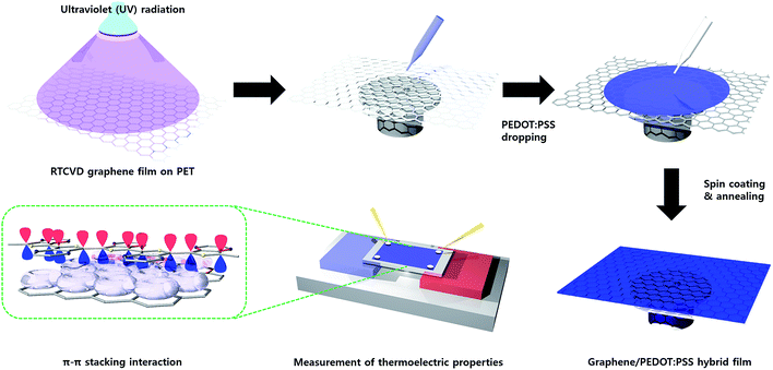 |
| | Scheme 1 Schematic hybridization process of RTCVD graphene and PEDOT:PSS, π–π stacking interaction interface between graphene and PEDOT:PSS chains. | |
Morphology analysis of the RCG/P hybrid film
AFM topology images of the RTCVD graphene film and the RCG/P hybrid film are shown in Fig. 1. The surface of the graphene film contained numerous defects, as shown in Fig. 1(a), due to the transfer process from the Cu foil to the PET substrate (AFM image of RTCVD graphene on the Cu foil is shown in Fig. S3†). Numerous graphene creases led to serious problems such as the deterioration of the sheet resistance and its physical strength.24–26 On the other hand, the surface of the RCG/P hybrid film displays the wrinkling and folding of the graphene sheet covered with a PEDOT:PSS thin film (see Fig. 1(b)).
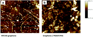 |
| | Fig. 1 AFM images of (a) RTCVD graphene, and (b) the PEDOT:PSS coated graphene. | |
Raman studies of the RCG/P hybrid film
The hybridization process improves not only the surface uniformity of the graphene film, but also its electrical properties. We expect the interaction between the PEDOT:PSS layer and graphene sheet to result in a synergic effect of the electrical properties in the RCG/P hybrid film. In other words, π–π stacking interaction enhances the electrical conductivity and thermoelectric properties of the RCG/P hybrid film. To analyse the interfacial interactions, we obtained the Raman spectra of the RTCVD graphene and RCG/P hybrid film. The typical Raman shifts of graphene are the G peak at about 1582 cm−1 and the 2D peak at about 2700 cm−1.27 As shown in Fig. 2(b), the G and 2D peaks of RTCVD graphene appear in 1598 cm−1 and 2705 cm−1, respectively. In the case of the RCG/P hybrid film, these bands are observed at 1605 cm−1 and 2726 cm−1 (see Fig. 2(a)). This red shift in the Raman spectrum of the conducting polymer/graphene composites is the most clear evidence confirming the interaction between the PEDOT:PSS chains and graphene (i.e. π–π stacking interaction).28 Therefore, the π–π stacking interaction is an important mechanism that accounts for the enhanced electrical conductivity and thermoelectric performance of the RCG/P hybrid film.29,30 In Fig. 2(a), the other peaks identified between 1200 and 1500 cm−1 are the characteristic peaks of PEDOT:PSS. The peaks at 1260 cm−1, 1367 cm−1, 1436 cm−1, and 1502 cm−1 correspond to the C–C interring stretching, C–C stretching, C![[double bond, length as m-dash]](https://www.rsc.org/images/entities/char_e001.gif) C symmetric stretching, and C
C symmetric stretching, and C![[double bond, length as m-dash]](https://www.rsc.org/images/entities/char_e001.gif) C asymmetric stretching vibrations, respectively.31–33
C asymmetric stretching vibrations, respectively.31–33
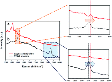 |
| | Fig. 2 Raman spectra of (a) the graphene/PEDOT:PSS hybrid film and (b) RTCVD graphene. The expansion spectra of the G peak position, and the expansion spectra of the 2D peak position are also shown. | |
Transmittance of the RCG/P hybrid film
We also obtained the optical transmittance (at 550 nm) of the RTCVD graphene film and RCG/P hybrid films, which were coated using various spin rates (500, 1000, 3000 rpm), using a UV-Vis spectrophotometer. As shown in Fig. 3, the transmittance of the RTCVD graphene film is 95%, and those of the RCG/P hybrid films are 88.3% at 500 rpm, 92.0% at 1000 rpm, and 93.9% at 3000 rpm. In accordance with the rotation speeds of the spin coater, the RCG/P hybrid films exhibit small differences in their transmittance. In particular, the result of the RCG/P hybrid film coated at 3000 rpm indicates that the PEDOT:PSS conducting layer absorbed only 1.1% of visible light at 550 nm. Furthermore, the hybrid films include excellent electrical and thermoelectric properties that will be described below.
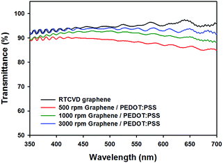 |
| | Fig. 3 Transmittance spectra of RTCVD graphene and graphene/PEDOT:PSS hybrid films, which were coated using various spin speeds (500, 1000, 3000 rpm). | |
Sheet resistance of the RCG/P hybrid film
Fig. 4(a) shows the sheet resistance of the pristine PEDOT:PSS films, RTCVD graphene films, and the RCG/P hybrid films. The average sheet resistance of the untreated RTCVD graphene films is about 282 Ω sq−1. The sheet resistance of the PEDOT:PSS thin films changes according to the rotational speed of the spin coater. As shown in our previous study,34 the thickness of the films is totally dependent on the spin rate of the coating process and it correlates with the electrical properties. The sheet resistance of the PEDOT:PSS thin film increase with increasing spin rate due to a decrease in the thickness of the PEDOT:PSS film. Although a similar trend is observed in the RCG/P hybrid films, there is an excellent improvement in the sheet resistance, in comparison with the untreated graphene film. In other words, as mentioned earlier, the π–π stacking interaction between the graphene and the PEDOT chains results in the enhanced electrical properties of the RCG/P hybrid films.35 The thickness of the RCG/P hybrid films was shown in Fig. S1, which is published as ESI.†
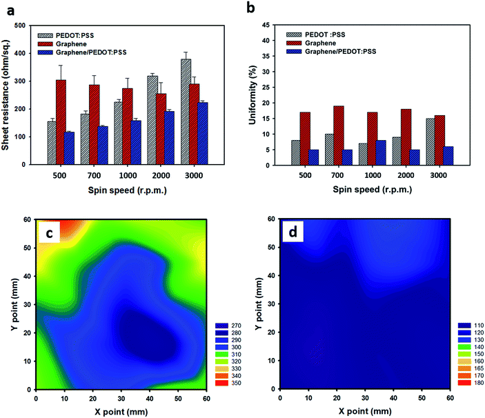 |
| | Fig. 4 (a) Sheet resistance and (b) uniformity of RTCVD graphene films, pristine PEDOT:PSS films, and graphene/PEDOT:PSS hybrid films, which were obtained using various spin speeds (500, 700, 1000, 2000, 3000 rpm). Sheet resistance mapping image of (c) RTCVD graphene, and the (d) graphene/PEDOT:PSS hybrid film at 500 rpm. | |
A reduction in the number of defects in RTCVD graphene covered with the PEDOT:PSS thin film is also shown to be in a uniformity at different spin speeds (see Fig. 4(b)); it is given by the following equation:
| Uniformity (%) = [[(Max. Rs − Min. Rs)/2]/Ave. Rs] × 100 |
where
Rs is the sheet resistance. A higher uniformity value means that the film has a non-uniform surface. After the hybrid process, the uniformity of the untreated graphene films decrease by up to 14%. To effectively express the variation of the sheet resistance, we obtained a mapping image of the sheet resistance of the RTCVD graphene film (60 mm × 60 mm) and the RCG/P hybrid film (60 mm × 60 mm) by measuring the sheet resistance at 25 spots on the films. As shown in
Fig. 4c and d, the RCG/P hybrid film has a consistent sheet resistance, in comparison with the untreated graphene film. Raman spectral mapping measurements were conducted to further study the uniformity of graphene and the RCG/P hybrid film (see Fig. S2 in ESI
†). The Raman mapping spectrum of the RTCVD graphene film is non-uniform and exhibits dissimilar brownish chrominance. On the other hand, the mapping image of the RCG/P hybrid film shows a relatively uniform reddish chrominance. The results indicate that the surface of the RCG/P hybrid film is sufficiently covered with PEDOT:PSS, in comparison with RTCVD graphene. Consequently, the PEDOT:PSS layer helps to heal the defects of the graphene film and improves its electrical properties. The results suggest that over-coating the graphene film with a PEDOT:PSS solution allowed for the conductive film to have the uniform electrical property with only a little decline of the transmittance.
Thermoelectric behavior of the RCG/P hybrid film
Fig. 5(a) shows the electrical conductivity measured by the Van der Pauw method of the pristine PEDOT:PSS films and the RCG/P hybrid films at 500, 700, 1000, 2000, and 3000 rpm. The average electrical conductivity of the pristine PEDOT:PSS films is 697.5 (±12.5) S cm−1, regardless of the spin speed. As the spin speed is increased, the electrical conductivity of the PEDOT:PSS films slightly decreases due to a change of PEDOT:PSS ratio in the film surface.34 In the case of the electrical conductivity of the RCG/P hybrid films, the conductivity increases from 747 to 1096 S cm−1 when the rotational speed is increased from 500 rpm to 3000 rpm, respectively. The maximum electrical conductivity of the RCG/P hybrid film is 1096 S cm−1 at 3000 rpm, and its transmittance is higher than 93.9% (see Fig. 3). It is observed that the thinner the PEDOT:PSS layer, which was found to act as the conducting layer, the better the conductivity of the RCG/P hybrid film. The conductivity increase is as a result of π–π interaction between the PEDOT backbone and graphene. The strong interaction between each component enhances the charge carrier mobility. An electrical conductivity of the thin film made up of the same material is generally constant, regardless of thickness of the conducting layer. However, in the case of the RCG/P hybrid film, as the thickness of the PEDOT:PSS layer is decreased, the electrical conductivity is enhanced due to the high carrier mobility of the graphene. We also observed the thermoelectric properties of the pristine PEDOT:PSS film and the RCG/P hybrid films depending on the rotational speed of the spin coater (see Fig. 5(b)). In comparison with the Seebeck coefficient of the PEDOT:PSS film, the one for the RCG/P hybrid film at 3000 rpm increases from 19.8 to 23.0 μV K−1. Therefore, the enhancement of the electrical conductivity and Seebeck coefficients results in an increased power factor. In other words, the π–π stacking interaction between the PEDOT chains and graphene induces an enhanced power factor of the RCG/P hybrid films. A figure of merit is calculated using the following equation:
where σ, S, T, and κ are the electrical conductivity, Seebeck coefficient, Kelvin temperature, and thermal conductivity, respectively. The power factor can be obtained by σ S2, and ZT represents the figure of merit of the thermoelectric materials. The power factor of the RCG/P hybrid film at 3000 rpm is 57.9 μW m−1 K−2. This value is about 2 times larger than that of the pristine PEDOT:PSS film, which is 28.1 μW m−1 K−2, and greater than 1.5 times in comparison with that in our previous study (see Table 1).21 The average experimental value of the Seebeck coefficient of the untreated graphene film is 30.0 μV K−1. This value is larger than that of the RCG/P hybrid film at 3000 rpm. Nevertheless, graphene is not ideal for use as a thermoelectric material because of its high thermal conductivity.36,37 When graphene is sufficiently covered with the organic polymer, the thermal conductivity of the graphene/polymer composites is reduced to a minimum of four orders of magnitude due to the low thermal conductivity of the polymer.38 Therefore, we expect that the ZT value of the RCG/P hybrid film is much larger than that of the graphene film.
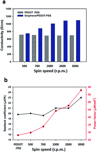 |
| | Fig. 5 (a) Electrical conductivity; and (b) Seebeck coefficient and power factor of pristine PEDOT:PSS, and graphene/PEDOT:PSS hybrid films, which were obtained using various spin speeds (500, 700, 1000, 2000, 3000 rpm). | |
Table 1 Electrical and thermoelectric properties of PEDOT:PSS/carbon materials composites, in comparison with previous work21
| Sample |
Electrical conductivity (S cm−1) |
Seebeck coefficient (μV K−1) |
Power factor (μW mK−2) |
Thermal Conductivity (W mK−1) |
Figure of merit ZT |
| PEDOT:PSS/MWCNT 5 wt% |
612 |
19.0 |
22.09 |
0.345 |
0.019 |
| PEDOT:PSS/graphene 5 wt% |
638 |
20.7 |
27.34 |
0.338 |
0.024 |
| PEDOT:PSS/graphene/MWCNT 5 wt% |
689 |
23.2 |
37.08 |
0.360 |
0.031 |
| RCG/P hybrid film (3000 rpm) (this work) |
1096 |
28.1 |
57.9 |
|
|
Bending tests of the graphene film and RCG/P hybrid films
A bending test of the RCG/P hybrid films was conducted to evaluate the films' bending stability. The bending test involved bending the graphene film and the RCG/P hybrid films (40 mm × 40 mm) to a radius 5 mm, for up to 1000 iterations (Fig. 6). As the graphene film is bent repeatedly, its sheet resistance increases and a high retention of 190% is recorded. Although the graphene film has excellent mechanical properties, its electrical properties deteriorated at 1000 cycles of the bending test.39,40 However, the RCG/P hybrid film showed a 111% retention at 1000 rpm and 115% retention at 3000 rpm. We assume that the PEDOT:PSS thin film, which acted as conducting layer on the graphene film, effectively prevented further damage to the film.41,42 In the case of the Seebeck coefficient, both the graphene film and hybrid films exhibit a small variation of bending test, as shown in Fig. 6(b). These results demonstrate that the RCG/P hybrid films have a highly stable flexibility and durability.
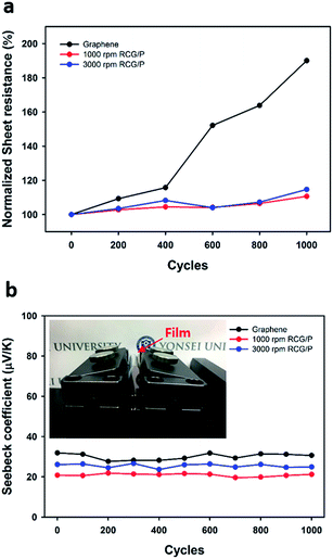 |
| | Fig. 6 (a) Plot of the sheet resistance and (b) Seebeck coefficient versus the bending cycle number of the graphene film, and RCG/P hybrid films (1000, 3000 rpm). | |
Conclusions
In summary, we investigated a transparent and flexible hybrid film made up of RTCVD graphene and poly (3,4-ethyldioxythiophene):poly (styrene sulfonate) as a thermoelectric generator. The RCG/P hybrid film was developed via a facile wet coating process. The PEDOT:PSS that was used as a conducting layer improved the sheet resistance of the graphene film without a loss in transmittance. In comparison with the bare graphene film, the sheet resistance of the RCG/P hybrid film, which had been spin coated at 1000 rpm, showed a 48% decrease, and its transmittance was 92%. In addition, the maximum power factor of the RCG/P hybrid film at 3000 rpm was 57.9 μW m−1 K−2. Despite a slight decrease in the Seebeck coefficient of graphene, the higher ZT of the RCG/P hybrid film was expected due to its low thermal conductivity. The enhanced results demonstrated that the RCG/P hybrid film is an effective strategy to produce conductive polymer and graphene composites. More remarkably, the PEDOT:PSS thin film reduced the surface defects of the graphene film and improved its bending stability by constraining the distortion of graphene during the bending stress. The present study inspires further improvement of thermoelectric materials for flexible and transparent devices.
Acknowledgements
This study was supported by the Nano-Material Technology Development Program through the National Research Foundation of Korea (NRF), funded by the Ministry of Science, ICT & Future Planning (MSIP, Korea) (NRF-2014M3A7B4050960/2014M3A7B4051745). This research was supported by Priority Research Centers Program through the National Research Foundation of Korea (NRF) funded by the Ministry of Education, Science and Technology (2009-0093823).
References
- Q. Zhang, Y. Sun, W. Xu and D. Zhu, Advanced Materials, 2014, 26, 6829–6851 CrossRef CAS PubMed.
- N. Dubey and M. Leclerc, J. Polym. Sci., Part B: Polym. Phys., 2011, 49, 467–475 CrossRef CAS.
- H. Kaneko, T. Ishiguro, A. Takahashi and J. Tsukamoto, Synth. Met., 1993, 57, 4900–4905 CrossRef CAS.
- D. Yoo, J. J. Lee, C. Park, H. H. Choi and J.-H. Kim, RSC Adv., 2016, 6, 37130–37135 RSC.
- J. Li, X. Tang, H. Li, Y. Yan and Q. Zhang, Synth. Met., 2010, 160, 1153–1158 CrossRef CAS.
- N. Kemp, A. Kaiser, H. Trodahl, B. Chapman, R. Buckley, A. Partridge and P. Foot, J. Polym. Sci., Part B: Polym. Phys., 2006, 44, 1331–1338 CrossRef CAS.
- L. Bao-Yang, L. Cong-Cong, L. Shan, X. Jing-Kun, J. Feng-Xing, L. Yu-Zhen and Z. Zhuo, Chin. Phys. Lett., 2010, 27, 057201 CrossRef.
- Y. Xuan, X. Liu, S. Desbief, P. Leclère, M. Fahlman, R. Lazzaroni, M. Berggren, J. Cornil, D. Emin and X. Crispin, Phys. Rev. B: Condens. Matter Mater. Phys., 2010, 82, 115454 CrossRef.
- W. Cho, J. K. Hong, J. J. Lee, S. Kim, S. Kim, S. Im, D. Yoo and J. H. Kim, RSC Adv., 2016, 6, 63296–63303 RSC.
- G.-H. Kim, L. Shao, K. Zhang and K. P. Pipe, Nat. Mater., 2013, 12, 719–723 CrossRef CAS PubMed.
- J. Luo, D. Billep, T. Waechtler, T. Otto, M. Toader, O. Gordan, E. Sheremet, J. Martin, M. Hietschold and D. R. Zahn, J. Mater. Chem. A, 2013, 1, 7576–7583 CAS.
- J. Roh, S. W. Sohn, K. H. Oh, P. W. Voorhees and W. Lee, Nano Lett., 2009, 9, 2867–2872 CrossRef PubMed.
- R. Venkatasubramanian, T. Colpitts, E. Watko, M. Lamvik and N. El-Masry, J. Cryst. Growth, 1997, 170, 817–821 CrossRef CAS.
- A. I. Boukai, Y. Bunimovich, J. Tahir-Kheli, J.-K. Yu, W. A. Goddard Iii and J. R. Heath, Nature, 2008, 451, 168–171 CrossRef CAS PubMed.
- C. Gao and G. Chen, Compos. Sci. Technol., 2016, 124, 52–70 CrossRef CAS.
- Y. Zhao, G.-S. Tang, Z.-Z. Yu and J.-S. Qi, Carbon, 2012, 50, 3064–3073 CrossRef CAS.
- K. Xu, G. Chen and D. Qiu, J. Mater. Chem. A, 2013, 1, 12395–12399 CAS.
- Y. Du, K. F. Cai, S. Z. Shen, B. An, Z. Qin and P. S. Casey, J. Mater. Sci.: Mater. Electron., 2012, 23, 870–876 CrossRef CAS.
- S. K. Yee, N. E. Coates, A. Majumdar, J. J. Urban and R. A. Segalman, Phys. Chem. Chem. Phys., 2013, 15, 4024–4032 RSC.
- W. Son, S. H. Lee, H. Park, H. H. Choi and J. H. Kim, J. Electron. Mater., 2016, 45, 2935–2942 CrossRef CAS.
- D. Yoo, J. Kim, S. H. Lee, W. Cho, H. H. Choi, F. S. Kim and J. H. Kim, J. Mater. Chem. A, 2015, 3, 6526–6533 CAS.
- J. Ryu, Y. Kim, D. Won, N. Kim, J. S. Park, E.-K. Lee, D. Cho, S.-P. Cho, S. J. Kim and G. H. Ryu, ACS Nano, 2014, 8, 950–956 CrossRef CAS PubMed.
- D. Jung, Y.-H. Ko, J. Cho, P. D. Adhikari, S. I. Lee, Y. Kim, W. Song, M. W. Jung, S. W. Jang and S. Y. Lee, Appl. Surf. Sci., 2015, 357, 287–292 CrossRef CAS.
- W. Zhu, T. Low, V. Perebeinos, A. A. Bol, Y. Zhu, H. Yan, J. Tersoff and P. Avouris, Nano Lett., 2012, 12, 3431–3436 CrossRef CAS PubMed.
- S. J. Chae, F. Güneş, K. K. Kim, E. S. Kim, G. H. Han, S. M. Kim, H. J. Shin, S. M. Yoon, J. Y. Choi and M. H. Park, Advanced Materials, 2009, 21, 2328–2333 CrossRef CAS.
- B.-J. Park, J.-S. Choi, H.-S. Kim, H.-Y. Kim, J.-R. Jeong, H.-J. Choi, H.-J. Jung, M.-W. Jung, K.-S. An and S.-G. Yoon, Sci. Rep., 2015, 5, 1–7 Search PubMed.
- L. Malard, M. Pimenta, G. Dresselhaus and M. Dresselhaus, Phys. Rep., 2009, 473, 51–87 CrossRef CAS.
- Q. Yao, L. Chen, W. Zhang, S. Liufu and X. Chen, ACS Nano, 2010, 4, 2445–2451 CrossRef CAS PubMed.
- Y. Yao, H. Dong and W. Hu, Advanced Materials, 2015, 28, 4513–4523 CrossRef PubMed.
- H. Sirringhaus, P. Brown, R. Friend, M. M. Nielsen, K. Bechgaard, B. Langeveld-Voss, A. Spiering, R. A. Janssen, E. Meijer and P. Herwig, Nature, 1999, 401, 685–688 CrossRef CAS.
- J. Ouyang, Q. Xu, C.-W. Chu, Y. Yang, G. Li and J. Shinar, Polymer, 2004, 45, 8443–8450 CrossRef CAS.
- M. Łapkowski and A. Proń, Synth. Met., 2000, 110, 79–83 CrossRef.
- S. Garreau, J. Duvail and G. Louarn, Synth. Met., 2001, 125, 325–329 CrossRef.
- D. Yoo, W. Son, S. Kim, J. J. Lee, S. H. Lee, H. H. Choi and J. H. Kim, RSC Adv., 2014, 4, 58924–58929 RSC.
- G. H. Kim, D. H. Hwang and S. I. Woo, Phys. Chem. Chem. Phys., 2012, 14, 3530–3536 RSC.
- A. A. Balandin, S. Ghosh, W. Bao, I. Calizo, D. Teweldebrhan, F. Miao and C. N. Lau, Nano Lett., 2008, 8, 902–907 CrossRef CAS PubMed.
- A. A. Balandin, Nat. Mater., 2011, 10, 569–581 CrossRef CAS PubMed.
- M. Wang, D. Galpaya, Z. B. Lai, Y. Xu and C. Yan, Int. J. Smart Nano
Mater., 2014, 5, 123–132 CAS.
- K. S. Kim, Y. Zhao, H. Jang, S. Y. Lee, J. M. Kim, K. S. Kim, J.-H. Ahn, P. Kim, J.-Y. Choi and B. H. Hong, Nature, 2009, 457, 706–710 CrossRef CAS PubMed.
- H. Tian, Y. Shu, Y.-L. Cui, W.-T. Mi, Y. Yang, D. Xie and T.-L. Ren, Nanoscale, 2014, 6, 699–705 RSC.
- C.-K. Cho, W.-J. Hwang, K. Eun, S.-H. Choa, S.-I. Na and H.-K. Kim, Sol. Energy Mater. Sol. Cells, 2011, 95, 3269–3275 CrossRef CAS.
- J. G. Tait, B. J. Worfolk, S. A. Maloney, T. C. Hauger, A. L. Elias, J. M. Buriak and K. D. Harris, Sol. Energy Mater. Sol. Cells, 2013, 110, 98–106 CrossRef CAS.
Footnotes |
| † Electronic supplementary information (ESI) available. See DOI: 10.1039/c7ra02980b |
| ‡ These authors contributed equally to this work. |
|
| This journal is © The Royal Society of Chemistry 2017 |
Click here to see how this site uses Cookies. View our privacy policy here.  Open Access Article
 *a
*a

![[double bond, length as m-dash]](https://www.rsc.org/images/entities/char_e001.gif) C symmetric stretching, and C
C symmetric stretching, and C![[double bond, length as m-dash]](https://www.rsc.org/images/entities/char_e001.gif) C asymmetric stretching vibrations, respectively.31–33
C asymmetric stretching vibrations, respectively.31–33


