 Open Access Article
Remarkably improved electromechanical actuation of polyurethane enabled by blending with silicone rubber
Christophe Renarda,
Dongrui Wang *a,
Peng Han
 a,
Silai Xionga,
Yongqiang Wen
 a and
Zhi-Min Dang
 *b
*b
aDepartment of Chemistry, School of Chemistry and Biological Engineering, University of Science and Technology Beijing, Beijing, 100083, P. R. China. E-mail: wangdr@ustb.edu.cn
bState Key Laboratory of Power System, Institute of High Voltage and Insulation Technology, Department of Electrical Engineering, Tsinghua University, Beijing, 100083, P. R. China. E-mail: dangzm@tsinghua.edu.cn
First published on 25th April 2017
Abstract
Herein we report the highly improved electromechanical actuation of thermoplastic polyurethane (TPU) by blending with polydimethylsiloxane (PDMS) to construct a bicontinuous structure. TPU/PDMS blend films with various PDMS loadings were fabricated through a simple solution-assisted casting method. Infrared spectroscopy measurements confirmed that TPU and PDMS are thermodynamically incompatible with each other. For TPU80 with 80 parts of PDMS, a bicontinuous phase structure was achieved. The TPU80 film showed greatly decreased elastic modulus and improved elongation at break compared to pristine TPU. It also showed the highest dielectric constant among the TPU/PDMS blend films with various contents of PDMS due to strong interfacial polarization. Most importantly, the TPU80 film exhibited a maximum areal strain of 2.3% under an electric field of 40 V μm−1, which is about 60 times higher than that of pristine TPU. The results described in this work demonstrate that the construction of a bicontinuous interface structure at the micrometer scale is very effective to develop elastomers with superior electromechanical actuation performance.
1 Introduction
Dielectric elastomer actuators (DEAs) have aroused great interest in the past two decades due to their simple device structure, considerable electromechanical actuation strain, and wide range of applications in soft intelligent systems.1–6 DEAs can be simply constructed by placing one piece of elastomer film between two compliant electrodes. When the electrodes are connected into an external electric field, the insulating elastomer film will contract in thickness while expand in area under the pressure induced by the electrostatic forces.7,8 Up to now, DEAs with an electromechanical areal strain over 1600% have been achieved by optimizing the elastomer composition and the device structure.9 However, a main challenge hindering the commercialization of such soft actuations still lies in that the considerable actuation strain can only be realized under a high electric field of several tens kV mm−1.1,4,8,10 To conquer the challenge, many researchers have dedicated to fabricating elastomers with enhanced dielectric permittivity to improve the electrostatic pressure.8 Various ceramics with high dielectric permittivity,11,12 conductive nanomaterials,13,14 and organic strong polar molecules15–17 have been chemically/physically incorporated into the elastomers. Though the actuation of DEAs can be improved in some extent, the increase in elastic modulus and severe deterioration in dielectric strength limit the practical applications of such elastomers. Over the past few years, it is gradually realized that developing elastomers with low modulus is a more efficient approach to improve the electromechanical actuation. For instance, it is demonstrated that the actuated areal strain of DEAs can be largely enhanced by blending oil-type plasticizers into the rubber matrix.18–20 Very recently, it is reported that silicone rubbers with a bottlebrush-like molecular architecture exhibited ultralow elastic modulus and an over 300% areal strain under an electric field lower than 10 kV mm−1.21 All these findings confirmed that decreasing the elastic modulus of elastomers to reduce the blocking force is very promising for advanced DEAs.Among various elastomer candidates for DEAs, polyurethanes (PUs) are gaining increasing interest due to their relatively high permittivity, great breakdown strength, easy processability, and low cost.8,10,22 In addition, the versatility of PU chemistry allows tailoring the elastomer's dielectric and mechanical properties in a wide range, which might supply more suitable elastomers for DEAs.23–25 The main limitation of PUs as an ideal elastomer is the relatively huge elastic modulus, which is induced by the internal high-density hydrogen bonds. To improve the electromechanical actuation, carbon nanospheres,26 carbon nanotubes,27,28 graphene nanosheets,28,29 and organic strong polar azobenzenes30 have been blended into PU to construct composite elastomers. However, only limited actuated strain were observed in such PU composite systems due to their further increased elastic modulus and poor dielectric breakdown strength. Recently, Ning et al. have employed an organic molecule, diaminonaphthalene, to blend with PU and disturb the formation of hydrogen bonds. The modified PU with reduced elastic modulus exhibited a max areal strain of 2.6%.31 Very recently, a novel type of PU-polydimethylsiloxane (PDMS) interpenetrating network (IPN) was prepared by chemically grafting PDMS chains with PU chains.32 It is interesting to find that elastomers with reduced elastic modulus and enhanced electromechanical strain can be obtained by changing the chain length of PDMS. The optimized PU-based IPN showed a max actuated areal strain of 7.1%.32 However, the complicate chemical synthesis compromises the possibility of such IPN for practical DEAs.
Herein, we investigated the electromechanical actuation of immiscible PU/PDMS blend films prepared by a simple solution casting method with a wide range of composition to tune the micro-structure. A thermoplastic polyurethane elastomer (TPU) combining the low cost, easy processing of thermoplastic materials and elasticity of elastomers has been chosen for the PU. We found a bicontinuous structure of the PU/PDMS blends resulted in remarkably improved actuation strain. The morphology, mechanical properties, and dielectric properties of as-prepared PU/PDMS blends were studied and discussed in detail. We attribute the remarkably improvement in electromechanical actuation to the larger interfacial area in the bicontinuous structure, which is conducive to increase the interfacial polarization.
2 Experimental section
2.1 Materials
A polyether-based thermoplastic polyurethane elastomer (Elastollan 1185A®) (density, d = 1.12) was purchased from BASF and used as received. Tetrahydrofuran (THF), toluene, α,ω-dihydroxy-terminated PDMS (Mn = 90![[thin space (1/6-em)]](https://www.rsc.org/images/entities/char_2009.gif) 000 g mol−1, d = 0.97), tetraethylsiloxane (TEOS), and dibutyltin dilaurate (DBTDL) were analytical grade products and used as received.
000 g mol−1, d = 0.97), tetraethylsiloxane (TEOS), and dibutyltin dilaurate (DBTDL) were analytical grade products and used as received.
2.2 Fabrication of elastomer films
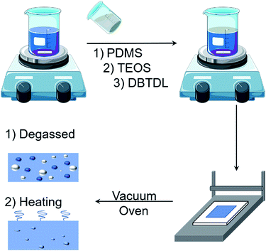
Plasticized TPU films were fabricated through a solution casting approach as represented in Scheme 1. TPU granules were firstly dissolved in THF and stirred at room temperature to form a homogeneous solution (10 wt%). Then a certain amount of PDMS was added into the solution and stirred for another 2 h before the introduction of TEOS as the cross-linker at a concentration of 10 wt% relative to the PDMS. After incorporation of TEOS, the stirring speed was increased to counteract an increasing in viscosity. After 1 h, the DBTDL catalyst was further added into the solution and stirred for 10 minutes. The resultant solution was casted onto a pre-cleaned glass plate, degassed under vacuum at room temperature for 2 h, and heated at 70 °C for 24 h. Plasticized TPU films with 20, 40, 60, 80, 100, and 200 parts per hundred resin (phr) of PDMS relative to the mass of TPU were prepared. Neat TPU and PDMS films were also prepared as control. As an example, the film made of 1 g TPU and 0.6 g PDMS corresponds to 60 phr of PDMS. The films are denoted as TPUx throughout the manuscript, where x is the content of PDMS (in phr) incorporated into the TPU. For example, the film containing 80 phr of PDMS is denoted as TPU80. The thickness of the films was controlled to be ca. 40 μm. Noting that the thicknesses of pure PDMS films and PU200 films are slightly higher (ca. 60 μm) due to the strong adhesion between the films and the glass plate.2.3 Characterizations
The cryo-fractured surfaces of plasticized TPU films were observed by scanning electron microscopy (SEM) using a Hitachi SU8010 under an accelerating voltage of 8 kV. Gold was sputtered onto the surfaces of samples prior to tests. Attenuated total reflectance Fourier transform infrared spectra (ATR-FTIR) of samples were measured using a Nicolet 6700 spectrometer equipped with a diamond crystal in the wavenumber range of 600–4000 cm−1. Dielectric constant and loss tangent of the plasticized PU films were measured by using an impedance analyzer (Agilent 4294A) over the frequency range from 1 kHz to 10 MHz under room temperature. Silver paste diluted in xylene were coated as electrodes with an area of 0.8 × 0.8 cm2 onto the surfaces of the specimens prior to tests. Tensile measurements were performed on an Instron 3365 tensile system under a constant strain rate of 50 mm min−1 at room temperature. Samples were prepared by cutting the films into a 40 × 5 mm2 rectangular shape. The Young's modulus (Y) was determined by the slope of stress–strain curves at the strain of 5%.The electromechanical actuation of the films was evaluated by integrating them into 4 mm diameter diaphragm-type actuators without pre-strain as described in our previous work.30 Graphite powders were coated onto both surfaces of elastomer films as the compliant electrodes. Direct current (DC) high voltage was supplied by connecting the actuators to a Boher HV supplier under a ramping rate of 150 V s−1. The voltage signal was monitored and recorded by using an oscilloscope (Tektronix DPO2012B). The actuated out-of-plane displacement was monitored by using a 635 nm laser position sensor (Panasonic HL-G105) that was focused on the centre of the actuators.
3 Results and discussion
3.1 Morphological structure of the blend films
The morphology of the TPU/PDMS blends with various PDMS contents was carefully characterized by SEM observation. The blend films were cryofractured and the cross-sections were observed. Typical SEM images are shown in Fig. 1. As expected, typical phase separation morphologies were clearly observed for the blends of the two incompatible polymers. Some wrinkles on the fractured surface are clearly observed for pristine TPU, suggesting the brittle nature of this sample in liquid nitrogen (Fig. 1a). By adding small amounts of PDMS into the TPU matrix, some dispersed spheres with the diameter of several micrometers are formed throughout the continuous TPU phase (Fig. 1b–d). The size of the spherical phase gradually increases as the increasing of PDMS content. It is also observed that the size of spheres exhibits a gradient distribution in the thickness direction. Conventionally, larger spheres were formed in the bottom side close to the glass substrate, which should be ascribed to the solvent evaporation process. As shown in Fig. 1e, the TPU/PDMS blend with 80 phr of PDMS exhibits relatively smooth cross-section when compared to other samples. The dispersed phase seems to show spherical shape with a smaller averaged diameter than that of TPU60. Considering the volume of PDMS in TPU80 is higher than that of TPU60, this observation suggests that a continuous phase structure of PDMS was formed in TPU80.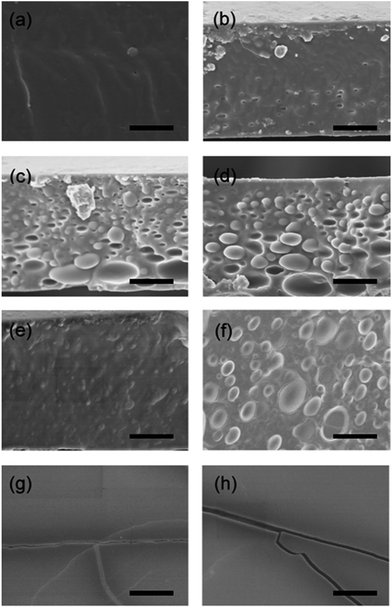 | ||
| Fig. 1 Typical SEM images of cryofractured cross-sections of (a) TPU0, (b) TPU20, (c) TPU40, (d) TPU60, (e) TPU80, (f) TPU100, (g) TPU200, and (h) PDMS. The scale bars correspond to 10 μm. | ||
To confirm the bicontinuous structure of TPU80, the cross-section was etched by toluene, which is a good solvent for PDMS while a bad solvent for TPU, and further checked. Typical SEM images of TPU blends after toluene etching are shown in Fig. 2. For TPU blends with PDMS content of 20, 40, and 60 phr, the morphologies after toluene etching confirm that PDMS is dispersed in TPU matrix with a spherical phase. While for the TPU80, many hollow tubes with diameter of several micrometers are clearly observed after selective extraction of PDMS (Fig. 2d), revealing the PDMS self-organized into a continuous phase throughout the TPU matrix.
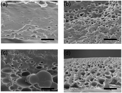 | ||
| Fig. 2 Typical SEM images of cross-sections of (a) TPU20, (b) TPU40, (c) TPU60, and (d) TPU80 after etched by using toluene. The scale bars correspond to 10 μm. | ||
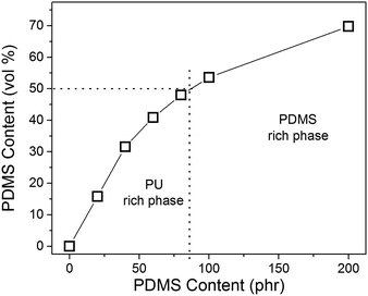
To evaluate the morphology evolution of the blends as a function of the volumetric inclusion of PDMS, the content of PDMS in phr was converted into volume fraction. As shown in Fig. 3, TPU80 corresponds to a PDMS volume content of 48% which is very close to 50%. This can explain well why the bicontinuous structure is obtained for this sample. When the content of PDMS goes beyond 50%, the phase inversion occurs. In Fig. 1f, it is clear that TPU spheres of several micrometers are uniformly dispersed in the PDMS matrix. In this sample, the volume fraction of PDMS is 53.6%. By comparing the morphologies of TPU60, TPU80, and TPU100, one can learn that the composition range to construct the bicontinuous phase is quite narrow for such TPU/PDMS blends. For TPU200 film, the morphology of its fractured surface is quite similar to that of pure PDMS. Some cracks can be seen on the surface, suggesting the brittle fracture occurred when immersing in liquid nitrogen.
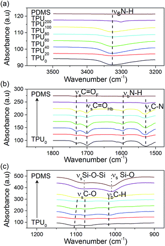
To verify if any interactions exist between TPU and PDMS chains in the blends, infrared spectroscopy was performed on the thin films using an attenuated total reflectance system. The spectra of the TPU blends with different PDMS loadings are shown in Fig. 4. Characteristic peaks corresponding to specific chemical bonds on TPU and PDMS chains are labeled in the figure. Negligible shift in the position of the characteristic peaks was observed, revealing the immiscibility between the two polymers at any given composition. It should be mentioned that the slight shift for the stretching vibration of C–O is attributed to the masking effect induced by the intense stretching vibration of Si–O–Si in PDMS, as proved by the ether linkage peak of siloxane in TPU200. However, the specific displacement of the N–H stretching vibration to lower wavenumber in TPU200 suggests the breaking of some TPU's hard segment domains into smaller ones induced by the confinement from the PDMS continuous phase. Such poor interactions between the PDMS and the PU have been well demonstrated in the literature dealing with such binary blends.33,34
3.2 Mechanical properties
Uniaxial tensile tests were performed to evaluate the mechanical behaviour of the blend films, which should be greatly affected by the various morphologies.36 Typical stress–strain curves for each sample are summarized in Fig. 5. All the films show the characteristic behaviour of their dominant phase. For blends with PDMS contents lower than 100 phr, the introduction of PDMS decreases the Young's modulus and the stress at break of TPU, without a severe reduction in elongation at break. While for the PDMS dominant films, the elongation at break is rather low due to the discontinuity of highly stretchable TPU phase. TPU200 performed poorly as an elastomer which may be caused by the synergetic effect of low content of TPU and the decrease of hard segment domain size in it as reflected by the IR spectrum (Fig. 4a).37 Surprisingly, the monotonous decreasing trend in the stress and strain at break of the blends by continuous incorporation of PDMS is disrupted for TPU60 and TPU80. It is suspected that the distribution of PDMS inclusions inside the TPU for TPU60 could locally form the bicontinuous structure as for TPU80. As compared, the blend TPU80 with the bicontinuous microstructure exhibits the best elongation at break and a moderate Young's modulus. Key data of mechanical properties of the TPU/PDMS blends are listed in Table 1. On the basis of these results, TPU80 seems promising for electromechanical actuation.38,39 | ||
| Fig. 5 Stress of TPU/PDMS blend films as a function of strain under uniaxial tensile. The stress–strain curves of pristine TPU and PDMS films are also exhibited for comparison. | ||
![[thin space (1/6-em)]](https://www.rsc.org/images/entities/char_2009.gif) δ) and relative dielectric constant (εr) at 1 kHz, along with the Young's modulus (Y), stress and strain at break (σmax and λmax) and the calculated electromechanical sensitivity for the different blends
δ) and relative dielectric constant (εr) at 1 kHz, along with the Young's modulus (Y), stress and strain at break (σmax and λmax) and the calculated electromechanical sensitivity for the different blends
| Samples | tan![[thin space (1/6-em)]](https://www.rsc.org/images/entities/char_2009.gif) δ@1 kHz δ@1 kHz |
εr@1 kHz | Y (MPa) | σmax (MPa) | λmax (n.a) | β (MPa−1) |
|---|---|---|---|---|---|---|
| TPU0 | 0.05 | 5.8 | 42.0 | 45.9 | 5.20 | 0.14 |
| TPU20 | 0.04 | 3.9 | 14.7 | 24.0 | 4.91 | 0.27 |
| TPU40 | 0.04 | 3.7 | 12.4 | 16.1 | 4.09 | 0.30 |
| TPU60 | 0.05 | 4.6 | 11.5 | 25.0 | 4.47 | 0.40 |
| TPU80 | 0.05 | 5.1 | 8.7 | 29.4 | 6.16 | 0.59 |
| TPU100 | 0.11 | 3.9 | 6.5 | 6.9 | 5.19 | 0.60 |
| TPU200 | 0.09 | 2.7 | 2.9 | 0.20 | 0.50 | 0.93 |
| PDMS | <0.01 | 3.0 | 0.6 | 0.26 | 0.82 | 5.00 |
3.3 Dielectric properties
The dielectric properties of the TPU/PDMS blends were tested by using an impedance analyser in the frequency range of 102 to 107 Hz at room temperature. The dielectric constant and loss curves versus frequency are summarized in Fig. 6. In Fig. 6a, strong loss tangent peaks at low frequency side (below 1 kHz) can be observed for all the blend samples, which should be ascribed to the well-known interfacial polarization. This is also proved by the observation that no strong loss tangent peaks in the spectra of pristine TPU and PDMS. The interfacial polarization comes from the space charges trapped on interfaces of TPU and PDMS phases.22 At frequency range of 104 to 107 Hz, TPU/PDMS blends show monotonically descending loss tangent as the increase of PDMS content. This should be well-understood by the decrease of polar group numbers packing in the blends and the resulting reduction of dipole orientation polarization. All the blends show relatively low loss tangent values (<0.1) in high frequency side, which is acceptable for electromechanical actuation applications.1,4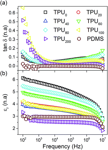 | ||
| Fig. 6 (a) Dielectric loss tangent and (b) relative dielectric constant of TPU/PDMS blends at room temperature. | ||
The relative dielectric constant of the blends is shown as Fig. 6b. As expected, the introduction of PDMS with low dielectric constant (∼3.0@1 kHz) decreased TPU's dielectric constant at the measured frequency range. Surprisingly, TPU200 showed quite low dielectric constant even lower than the pure PDMS. This may be caused by the poor interface between dispersed TPU phase and PDMS matrix, on which some microvoids within trapped air are formed. Except TPU200, other blend samples exhibit reasonable dielectric constant curves. The dielectric constant at 1 kHz of the blends are also listed in Table 1. It can be observed that the TPU80 reached the highest value of 5.1 among the binary blends. Considering the content of PDMS in this sample is even higher than in TPU20, TPU40, and TPU60, the relatively high dielectric constant should mainly benefit from the interfacial polarization.
To clarify the effect of interface on the dielectric constant, we estimated the contact area of PDMS phase and TPU phase in the blends. Using the isoperimetric inequality involving the surface area of an enclose surface with a given perimeter, the product Ψ × P was taken to reflect the interfacial contact between the inclusion and the volumetric dominant phase. P is the sum of perimeter of all the quasi round inclusions observed in cross-sectional SEM images, which is obtained by calculating the product of their averaged perimeter and number following eqn (1):
 | (1) |
| p = πD | (2) |
While the sphericity Ψ, which defines the compactness of a round object, can be calculated following the eqn (3),
 | (3) |
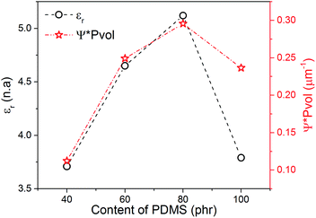 | ||
| Fig. 7 Variation of the relative dielectric constant and areal interfacial contact between TPU and PDMS (Ψ × Pvol) as a function of the PDMS content in the blends. | ||
3.4 Electromechanical actuation
To predict the actuation performance of TPU/PDMS blends under a DC electric field, the electromechanical sensitivity (β = εr/Y) is calculated by using the Young's modulus (Y) and the εr taken at 1 kHz.17,30 The results are listed in Table 1. The obtained data prove that increasing β values are obtained as the increasing of PDMS contents in the blends, which suggests that the reduction in Y is more effective for the improvement of electromechanical actuation. The TPU200 and neat PDMS possess the highest β values. However, based on the results of tensile tests, the stretchability of these two samples is rather poor. Therefore, it is doubtful that if high actuated strain can be achieved for these two films.To verify the validity of the prediction, the experimental actuation of the TPU/PDMS blend films was examined by fabricating them into diaphragm-type actuators as represented in Fig. 8a.30 Fig. 8b displays the experimental displacement of the films as a function of the driving electric field. The experiments were stopped at the electric field strength of 90 V μm−1 if no electrical breakdown occurred before. Except the TPU200 and pure PDMS with poor mechanical properties, all the blend films performed better than pristine TPU. At a given electric field, improved actuated strain can be induced by blending the PDMS and the TPU together even at the lowest content of PDMS (such as TPU20). Furthermore, a continuous reduction in required applied electric-field to reach the maximum actuated displacement, following a known trend induced by the reduction in the elastic modulus, can also be seen in Fig. 8b.
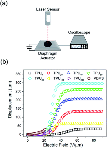 | ||
| Fig. 8 (a) Schematic representation of a diaphragm-type actuation test, and (b) electric field induced displacement for different TPU/PDMS blends. | ||
In addition, the electromechanical actuation behaviour of the blend films could be classified into two categories depending which polymer acts as the dominant phase. In PDMS-rich blends, the addition of TPU cannot largely increase the actuated displacement. For the TPU200 film, it can be easily understood by taking the seriously deteriorated elasticity into account. However, this is not the case in the TPU100. Thus, we suppose that the relatively low actuated strain for the PDMS-rich blends is partially caused by the low compatibility between the PDMS phase and the compliant electrodes applied onto it. Indeed, even the pure PDMS film behaves worse than those values reported in literature using other type compliant electrode materials.39,44,45 However, the study on the compliant electrode was beyond the scope of this work. Moreover, the degree of crosslinking affects the actuation response of PDMS-based DEAs as shown in the literature.4,19,21 Therefore, the current condition of crosslinking should be one reason for such low actuation.
A ten-fold improvement in the maximum displacement is observed for TPU80 when comparing to TPU0, while reducing 30% of the applied electric field. The highly improved electromechanical actuation is the result of the synergetic effect of dielectric and mechanical properties. Both of them benefit from the bicontinuous structure as discussed previously. Such an improvement may be interesting for designing other type composite elastomers with bicontinuous structures towards advanced DEAs.46
The measured actuated displacement was further converted into the areal strain (SA) which is defined as follows:
| SA = λA − 1 | (4) |
 | (5) |
| Elastomers | Actuator form | Max SA (%) | Electric field@max SA (V μm−1) | SA@50% of Ebd (%) | Ref. |
|---|---|---|---|---|---|
| a Calculated based on the thickness strain using A/A0 = t/t0 − 1 under an isochoric condition. | |||||
| TPU0 | Diaphragm | 0.04 | 60 | ≪0.1 | This work |
| TPU80 | Diaphragm | 2.3 | 42 | 2.3 | This work |
| TPU/disperse red 19 (1 phr) | Diaphragm | 0.8a | 57 | 0.1a | 30 |
| TPU/diaminonaphthalene (30 phr) | Circular disc | 2.6 | 20 | 1.3 | 31 |
| TPU/poly(ethylene glycol) 600 (80 phr) | Circular disc | 5.2 | 3 | 1.2 | 47 |
TPU/gelatin–glycerol (1![[thin space (1/6-em)]](https://www.rsc.org/images/entities/char_2009.gif) : :![[thin space (1/6-em)]](https://www.rsc.org/images/entities/char_2009.gif) 0.5) 0.5) |
Circular disc | 5.2 | 0.55 | 3.0 | 48 |
| Polyaniline/poly(copper phthalocyanine)/PU (14/15/85) | Not reported | 10.2a | 20 | 2.1a | 49 |
| PU/ionic liquid/poly(3,4-ethylenedioxythiophene):poly(styrene sulfonate) (40 wt% ionic liquid within PU) | Unimorph | 0.3 | 2 | 0.2 | 50 |
We also tested the cyclic actuation performance of the TPU80 film. Under a cyclically linearly changed electric field with a ramp rate of ca. 150 V s−1, the TPU80 film showed quite stable actuation response after first few activation cycles (as shown in Fig. 9). The stabilized actuated displacement is around 390 μm (or SA = 3.8%) at 35 V μm−1, which is slightly higher than the results presented in Fig. 8. Based on the cyclic actuation results, it can be expected that this TPU/PDMS blend with the bicontinuous structure is a good candidate for DEA in long-term practical applications.
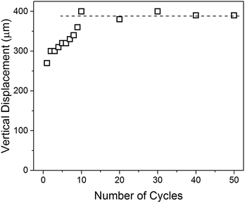 | ||
| Fig. 9 Continuous electromechanical actuation of TPU80 film under a cyclically linearly changed electric field from 0–35 V μm−1 with a ramp rate of 150 V s−1. | ||
4 Conclusion
Elastomer films composed of TPU and PDMS were prepared through a simple mixing and solution casting approach. The morphology of as-prepared elastomers can be well tuned by the volume fraction ratio of the two incompatible components. When the volume ratio of TPU to PDMS approached 1![[thin space (1/6-em)]](https://www.rsc.org/images/entities/char_2009.gif) :
:![[thin space (1/6-em)]](https://www.rsc.org/images/entities/char_2009.gif) 1, a bicontinuous structure was obtained. The bicontinuous structure remarkably enhanced the interfacial polarization and the dielectric constant of the blend film, that also give rise to a highly improved electromechanical actuation strain. Under the same measurement conditions, the TPU/PDMS blend film with the bicontinuous structure showed a max areal strain of 2.3%, which is about 60 times higher than that of bulk TPU film. More importantly, the highly improved actuation strain can be maintained after 50 cyclic actuation tests. These results demonstrate blend elastomers with micrometer-scale bicontinuous structures are very promising for developing high-performance electromechanical actuators.
1, a bicontinuous structure was obtained. The bicontinuous structure remarkably enhanced the interfacial polarization and the dielectric constant of the blend film, that also give rise to a highly improved electromechanical actuation strain. Under the same measurement conditions, the TPU/PDMS blend film with the bicontinuous structure showed a max areal strain of 2.3%, which is about 60 times higher than that of bulk TPU film. More importantly, the highly improved actuation strain can be maintained after 50 cyclic actuation tests. These results demonstrate blend elastomers with micrometer-scale bicontinuous structures are very promising for developing high-performance electromechanical actuators.
Acknowledgements
Financial support from National Natural Science Foundation of China (21574012, 51425201, 51377010), National Basic Research Program of China (2014CB239505), State Key Laboratory of Power Systems (No. SKLD16Z02), and Fundamental Research Funds for the Central Universities (FRF-BR-16-007A) are gratefully acknowledged.References
- P. Brochu and Q. Pei, Macromol. Rapid Commun., 2010, 31, 10–36 CrossRef CAS PubMed.
- S. Chiba and M. Waki, Recent Advances in Wireless Communications and Networks, InTech, 2011, pp. 435–534, ISBN 978-953-307-274-6 Search PubMed.
- I. A. Anderson, T. A. Gisby, T. G. McKay, B. M. O'Brien and E. P. Calius, J. Appl. Phys., 2012, 112, 041101 CrossRef.
- J. Biggs, K. Danielmeier, J. Hitzbleck, J. Krause, T. Kridl, S. Nowak, E. Orselli, X. Quan, D. Schapeler, W. Sutherland and J. Wagner, Angew. Chem., Int. Ed., 2013, 52, 9409–9421 CrossRef CAS PubMed.
- A. Khaldi, C. Plesse, F. Vidal and S. K. Smoukov, Adv. Mater., 2015, 16, 4418–4422 CrossRef PubMed.
- C. Larson, P. Beele, S. Li, S. Robinson, M. Totaro, L. Beccai, B. Mazzolai and R. Shepherd, Science, 2016, 351, 1071–1074 CrossRef CAS PubMed.
- R. Pelrine, R. Kornbluh and J. Joseph, Sens. Actuators, A, 1998, 64, 77–85 CrossRef CAS.
- R. Pelrine, R. Kornbluh, Q. Pei and J. Joseph, Science, 2000, 287, 836–839 CrossRef CAS PubMed.
- C. Keplinger, T. Li, R. Baumgartner, Z. Suo and S. Bauer, Soft Matter, 2012, 12, 285–288 RSC.
- M. Zhenyi, J. I. Scheinbeim, J. W. Lee and B. A. Newman, J. Polym. Sci., Part B: Polym. Phys., 1994, 32, 2721–2731 CrossRef.
- N. Xu, L. Hu, Q. Zhang, X. Xiao, H. Yang and E. Yu, ACS Appl. Mater. Interfaces, 2015, 7, 27373–27381 CAS.
- M. Poikelispää, A. Shakun, A. Das and J. Vuorinen, J. Appl. Polym. Sci., 2016, 133, 44116–44124 CrossRef.
- B. Guiffard, D. Guyomar, L. Seveyrat, Y. Chowanek, M. Bechelany, D. Cornu and P. Miele, J. Phys. D: Appl. Phys., 2009, 42, 055503 CrossRef.
- K. Yang, X. Huang, L. Fang, J. He and P. Jiang, Nanoscale, 2014, 6, 14740–14743 RSC.
- F. B. Madsen, A. E. Daugaard, S. Hvilsted, M. Y. Benslimane and A. Ladegaard-Skov, Smart Mater. Struct., 2013, 22, 104002 CrossRef.
- M. Dascalu, S. J. Dünki, J.-E. Q. Quinsaat, Y. S. Ko and D. M. Opris, RSC Adv., 2015, 5, 104516–104523 RSC.
- L. Zhang, D. Wang, P. Hu, J.-W. Zha, F. You, S.-T. Li and Z.-M. Dang, J. Mater. Chem. C, 2015, 3, 4883–4889 RSC.
- R. Shankar, A. K. Krishnan, T. K. Gosh and R. J. Spontak, Macromolecules, 2008, 41, 6100–6109 CrossRef CAS.
- M. Molberg, D. Crespy, P. Rupper, F. Nüesch, J.-A. E. Månson, C. Löwe and D. M. Opris, Adv. Funct. Mater., 2010, 20, 3280–3291 CrossRef CAS.
- H. Zhao, D.-R. Wang, J.-W. Zha, J. Zhao and Z.-M. Dang, J. Mater. Chem. A, 2013, 1, 3140–3145 CAS.
- M. Vatankhah-Varnoosfaderani, W. F. M. Daniel, A. P. Zhushma, Q. Li, B. J. Morgan, K. Matyjaszewski, D. P. Armstrong, R. J. Spontak, A. V. Dobrynin and S. S. Sheiko, Adv. Mater., 2017, 2, 1604209 CrossRef PubMed.
- Q. M. Zhang, J. Su, C. H. Kim, R. Ting and R. Capps, J. Appl. Phys., 1997, 81, 2770–2776 CrossRef CAS.
- D. B. Klinedinst, I. Yilgör, E. Yilgör, M. Zhang and G. L. Wilkes, Polymer, 2012, 53, 5358–5366 CrossRef CAS.
- C. Prisacariu, E. Scortanu and B. Agapie, J. Ind. Eng. Chem., 2013, 19, 113–119 CrossRef CAS.
- K. Petcharoen and A. Sirivat, Curr. Appl. Phys., 2013, 13, 1119–1127 CrossRef.
- Y. Yao, N. Ning, L. Zhang, T. Nishi and M. Tian, RSC Adv., 2015, 5, 23719–23726 RSC.
- G. J. H. Melvin, Q. Q. Ni and T. Natsuki, Polym. Compos., 2014, 37, 262–269 CrossRef.
- T. Chen, L. Pan, M. Lin, B. Wang, L. Liu, Y. Li, J. Qiu and K. Zhu, Polym. Test., 2015, 47, 4–11 CrossRef CAS.
- S. Liu, M. Tian, B. Yan, Y. Yao, L. Zhang, T. Nishi and N. Ning, Polymer, 2015, 56, 375–384 CrossRef CAS.
- C. Renard, D. Wang, B.-Z. Han and Z.-M. Dang, RSC Adv., 2015, 5, 82215–82226 RSC.
- N. Ning, B. Yan, S. Liu, Y. Yao, L. Zhang, T. W. Chan, T. Nishi and M. Tian, Smart Mater. Struct., 2015, 24, 032002 CrossRef.
- C. Tugui, S. Vlad, M. Lacob, C. D. Vargacini, L. Pricop and M. Cazacu, Polym. Chem., 2016, 7, 2709–2719 RSC.
- R. Hernandez, J. Weksler, A. Padsalgikar and J. Runt, Macromolecules, 2007, 40, 5441–5449 CrossRef CAS.
- M. P. Drupita, K. Naskar and G. B. Nando, RSC Adv., 2016, 6, 80065–80078 RSC.
- J. A. Gopi and G. B. Nando, Advances in Polymer Science and Technology: An International Journal, 2014, 4, 43–51 Search PubMed.
- J. A. Gopi and G. B. Nando, Int. J. Plast. Technol., 2015, 19, 288–308 CrossRef CAS.
- H. J. Qi and M. C. Boyce, Mech. Mater., 2005, 37, 819–837 CrossRef.
- H. Stoyanov, M. Kollosche, S. Risse, D. N. McCarthy and G. Kofod, Soft Matter, 2011, 7, 194–202 RSC.
- A. H. A. Razak, P. Szabo and A. Ladegaard-Skov, RSC Adv., 2015, 5, 53054–53062 RSC.
- S. Rudykh, A. Lewinstein, G. Ulner and G. de Botton, Appl. Phys. Lett., 2013, 102, 151905 CrossRef.
- R. N. Santra, S. Roy, V. K. Tikku and G. B. Nando, Adv. Polym. Technol., 1995, 14, 59–66 CrossRef CAS.
- P. Król, B. Król, J. Kozakiewicz, Z. Zapotoczny, B. Pilch-Pitera and S. Kozdra, Prog. Org. Coat., 2015, 81, 72–79 CrossRef.
- D. Ren, Z. Tu, C. Yu, H. Shi, T. Jiang, Y. Yang, D. Shi, J. Yin, Y.-W. Mai and R. K. Y. Li, Ind. Eng. Chem. Res., 2016, 55, 4515–4525 CrossRef CAS.
- I. J. Kim, K. Min, H. Park, S. M. Hong, W. N. Kim, S. H. Kang and C. M. Koo, J. Appl. Polym. Sci., 2014, 131, 40030 Search PubMed.
- F. B. Madsen, A. E. Daugaard, S. Hvilsted and A. Ladegaard-Skov, Macromol. Rapid Commun., 2016, 37, 378–413 CrossRef CAS PubMed.
- K. B. Subramani, E. Cakmak, R. J. Spontak and T. K. Gosh, Adv. Mater., 2014, 26, 2949–2953 CrossRef CAS PubMed.
- M. Tian, B. Yan, Y. Yao, L. Zhang, T. Nishi and N. Ning, J. Mater. Chem. C, 2014, 2, 8388–8397 RSC.
- M. Tian, Y. Yao, S. Liu, D. Yang, L. Zhang, T. Nishi and N. Ning, J. Mater. Chem. A, 2015, 3, 1483–1491 CAS.
- C. Huang, Q. M. Zhang, G. De Botton and K. Bhattacharya, Appl. Phys. Lett., 2004, 84, 4391–4393 CrossRef CAS.
- H. Okuzaki, S. Tagaki, F. Hishiki and R. Tanigawa, Sens. Actuators, B, 2014, 194, 59–63 CrossRef CAS.
| This journal is © The Royal Society of Chemistry 2017 |

