 Open Access Article
Creative Commons Attribution 3.0 Unported Licence
Synthesis of micro-mesoporous materials ZSM-5/FDU-12 and the performance of dibenzothiophene hydrodesulfurization†
Honglei Zhangab,
Longnian Han‡
b,
Aijun Duan *ac,
Chunming Xu*a,
Zhen Zhao
 a,
Yuechang Weia,
Guiyuan Jianga,
Jian Liu
 a,
Dong Wangb and
Zesheng Xiaa
aState Key Laboratory of Heavy Oil Processing, China University of Petroleum, Beijing 102249, P. R. China. E-mail: duanaijun@cup.edu.cn; xcm@cup.edu.cn
bCNOOC Research Institute of Oil and Petrochemicals, Beijing, 102209, China
cState Key Laboratory of Petrochemical Resource Processing and Process Intensification Technology, Guangxi University, Nanning, 530004, P. R. China
First published on 26th May 2017
Abstract
The micro-mesoporous materials ZF-x (ZSM-5-FDU-12, x = SiO2/Al2O3) with different molar ratios of SiO2/Al2O3 were synthesized by an in situ nano-assembly method with the ZSM-5 precursor serving as the silica source. The physicochemical properties of the supports and the corresponding catalysts were analyzed in detail by various techniques including SEM, TEM, XRD, nitrogen physisorption, FTIR, UV-Vis, pyridine IR, Raman and XPS. The nitrogen physisorption measurement showed that the composite ZF-130 possessed excellent physical properties compared to other ZF-x materials. In addition, the XPS spectra displayed that catalysts NiMo/ZF-x showed a higher sulfurization than NiMo/FDU-12, and the NiMo/ZF-130 exhibited the highest contents of MoS2 and NiMoS. In addition, DBT was employed as the probe molecule to evaluate the HDS (hydrodesulfurization) performance of the sulfide catalysts of NiMo/ZF-x under different weight hourly space velocities (WHSVs) 20–120 h−1, while NiMo/FDU-12 was used as the reference. Furthermore, the relationship between the structure of micro-mesoporous materials and the HDS activities of catalysts was systematically evaluated. The HDS efficiencies followed the order NiMo/ZF-130 > NiMo/ZF-110 > NiMo/ZF-150 > NiMo/ZF-90 > NiMo/ZF-70 > NiMo/FDU-12 under the operation conditions of 340 °C, 4.0 MPa, and H2/oil of 200 20–120 h−1. Compared to other NiMo/ZF-x catalysts, NiMo/ZF-130 displayed the highest efficiency of DBT HDS, 96.3% at 20 h−1, which could be attributed to the synergistic effects of its larger pore sizes (14.9 nm), greater specific surface area (352 m2 g−1), moderate B and L acid sites, and the highest ratios of Mo4+/Mo (58%) and NiMoS/NiT (64%).
1. Introduction
Environment problems caused by vehicle emissions are serious and have attracted much worldwide attention. Sulfur-containing compounds derived from transportation fuels actually produce SOx after fuel combustion and lead to acid rain and PM2.5 particles that cause respiratory diseases. Therefore, sulfur is one of the pollutants in fuels that should be removed. Moreover, the sulfur content in diesel and gasoline needs to meet strict fuel specifications with S content lower than 10 ppm.1 However, it is a great challenge to achieve ultra-deep desulfurization due to the increasingly heavy quality of crude oil. Fortunately, hydrodesulfurization (HDS) technology with catalysts is still one of the most effective approaches to produce highly clean products with a low sulfur content.2 Therefore, the preparation of a catalyst with superior performance is essential for the removal of sulfur from many materials.Supports are one of the crucial components of catalysts that can provide a platform and accelerate the dispersion of the metal components.3,4 The conventional Al2O3 carriers are widely used in the industrial hydrogenation of fuel oil and exhibits outstanding mechanical strength and hydrothermal stability. Nevertheless, its promiscuous pore structure and the lack of B acid sites are detrimental to the HDS reaction. Thus, aluminosilicate zeolites, such as ZSM-5, beta and Y, are considered as supports in the HDS process due to their high hydrothermal stability, favourable isomerization properties and particularly abundant B acid sites.5–7
Wu and co-workers prepared a series of metal cation-functionalized M+-ZSM-5 (M+ = H+, Al3+, Ca2+ and Ba2+) materials and the characterization results showed that H+-ZSM-5 possessed the most accessible acid sites.6 The B acids were derived from the bridge hydroxyl groups, which connected with Al and Si atoms, and the varying ratios of B acids to L acids coincided well with the different amounts and types of metal cations.
Nevertheless, the low pore sizes of ZSM-5 are unfavorable for their wide application in the HDS process since a great number of larger reactant molecules is involved in the reaction systems. In order to compensate for the deficiency of microporous zeolites, mesoporous silica materials have generated much interest in the catalysis field due to their extraordinary mass transfer capabilities.8–11
Huirache-Acuña and Cao investigated the catalytic properties of NiMoW/Al-HMS and NiMo/TiFDU-12, and both of them displayed ideal removal efficiencies of dibenzothiophene (DBT), which were attributed to the larger pore sizes and higher specific areas of the supports, as well as the average dispersion of sulfurized metal phases.10,11 Furthermore, NiMo/TiFDU-12 with a suitable B acid content performed better than NiMo/FDU-12 in the HDS reactivity.
Several researchers have focused on the preparation of micro-mesoporous composite materials due to the low crystallinity, inferior hydrothermal stability and poor acidity of mesoporous silica materials. Moreover, they applied these materials in various catalytic processes, and significant results were obtained under certain conditions.12–19 Gao prepared a novel hierarchical pore material and corresponding catalyst Pt/ZSM-5-SBA-15, which possessed a porous structure and high dispersion of Pt. Thus, it showed higher hydrogenation activity than the Pt/ZSM-5 and Pt/SBA-15 separately.13 Wu successfully synthesized a NiMo/ZSM-5-KIT-6 catalyst that revealed excellent 4,6-DMDBT HDS behavior, and the corresponding desulfurization rate is double as the conventional NiMo/Al2O3 catalyst. The outstanding catalytic behavior of NiMo/ZK-W was derived from the synergistic contribution of the hierarchical porous structure, which eliminated diffusion hindrances. The moderate Brönsted acid sites provided by ZSM-5 facilitated the isomerization of 4,6-DMDBT in the HYD desulfurization route and displayed an excellent hydrothermal stability, which prolonged the lifetime of the catalyst.19
For the HDS process, micro-mesoporous materials served as excellent supports that possessed not only good physical properties but also Lewis (L) and Brönsted (B) acid sites. The B acid sites can effectively favor the cleavages of C–S bonds, which dominate the rate of HDS. In addition, appropriate additives of Al species can prevent the active centers from agglomerating by modulating the interactions between supports and active metals, which finally facilitates the sulfurization of active components and improves the HDS efficiencies of the corresponding catalysts.10,11,19–21
The mesoporous silica material FDU-12, with a face-centered cubic (Fm3m) structure, has been widely used as a catalyst carrier in biotechnology, adsorption, immobilization and separation processes due to its high surface area and well-ordered pore channels with a long range.22–25 Generally speaking, a three-dimensional interlaced channel could efficiently diminish the hindrance to diffusion in comparison with the two-dimensional straight channel with similar pore sizes. In addition, FDU-12 possesses a larger cage pore size and easily tailored pore entrance size (4–9 nm), which are significant for the mass transfer of reactants and products.
In this research, ZSM-5-FDU-12-x (ZF-x) materials combined with an MFI topological structure and an Fm3m cage-like channel structure were successfully synthesized via an in situ nano-assembling method by employing a ZSM-5 precursor as a source of silicon. The molar ratios of SiO2/Al2O3 in ZF-x were controlled by adjusting the various amounts of ZSM-5 in the colloidal solution. Then, the corresponding catalysts were prepared by two-step incipient-wetness impregnation procedures and their HDS performances of DBT were evaluated under certain conditions. The properties of the materials and the sulfurized catalysts were characterized by different techniques. The results confirmed that ZF-x samples possessed a large pore diameter, high specific surface area and tunable acid sites. Prominent physical chemistry properties actually made it effective to disperse molybdenum species and develop MoS2 and NiMoS active component phases, which were conducive to improve the HDS reactions. Moreover, the effects of SiO2/Al2O3 ratios on the DBT HDS efficiency were explored. Then, the optimal ratio of SiO2/Al2O3 was determined, along with the characterization of these materials to rationalize the experimental observations.
2. Experimental and characterization
2.1 Synthesis of the materials
The micro-mesoporous materials ZF-x (x = SiO2/Al2O3) with different molar ratios of SiO2/Al2O3 were prepared by an in situ nano-assembly method. First, a ZSM-5 zeolite precursor solution was synthesized with a molar ratio of 1Al2O3![[thin space (1/6-em)]](https://www.rsc.org/images/entities/char_2009.gif) :
:![[thin space (1/6-em)]](https://www.rsc.org/images/entities/char_2009.gif) 30SiO2
30SiO2![[thin space (1/6-em)]](https://www.rsc.org/images/entities/char_2009.gif) :
:![[thin space (1/6-em)]](https://www.rsc.org/images/entities/char_2009.gif) 14.7TPABr
14.7TPABr![[thin space (1/6-em)]](https://www.rsc.org/images/entities/char_2009.gif) :
:![[thin space (1/6-em)]](https://www.rsc.org/images/entities/char_2009.gif) 17NaOH
17NaOH![[thin space (1/6-em)]](https://www.rsc.org/images/entities/char_2009.gif) :
:![[thin space (1/6-em)]](https://www.rsc.org/images/entities/char_2009.gif) 2000H2O. The specific procedure was as follows: 0.6 g of NaOH and 5.3 g TPABr were dissolved in 8 g of deionized water, and 10 g of colloidal silica was added into the previous solution with consistent stirring to obtain solution I. Solution II was derived from the mixture of 0.287 g of NaOH and 1.0 g of NaAlO2 in 10 g of distilled H2O. Afterwards, the homogenous gel solution was prepared by dripping solution II into solution I with persistent stirring for 4 h at ambient temperature. The aluminosilicate sol–gel solution was transferred into a polypropylene bottle and hydrothermally treated for 21 h at 443 K to obtain the ZSM-5 seed precursor. Second, ZF-x (x = 70, 90, 110, 130 and 150) was prepared by employing both a zeolite ZSM-5 seed and tetraethylorthosilicate (TEOS) as the silica source under the synergistic effect of inorganic salt additives of KCl. In the typical steps, 5 g of KCl, 2.0 g of TMB and 2.0 g of triblock copolymers EO106PO70EO106 (F127, BASF), used as a textural template agent, were dissolved in 120 ml of 2 M hydrochloric acid HCl solution and stirred for 24 h. Then, 2.0 TEOS and various amounts of ZSM-5 seed were added into the mixture and stirred for another 24 h at a constant temperature of 293 K, and the solution was transferred into a Teflon bottle and heated for 24 h at 373 K. The resultant mixture was filtered, washed and dried at 253 K to obtain the as-synthesized samples, which needed to be calcined for 6 h at 823 K to obtain micro-mesoporous materials, ZF-x, after the removal of the F127 template.
2000H2O. The specific procedure was as follows: 0.6 g of NaOH and 5.3 g TPABr were dissolved in 8 g of deionized water, and 10 g of colloidal silica was added into the previous solution with consistent stirring to obtain solution I. Solution II was derived from the mixture of 0.287 g of NaOH and 1.0 g of NaAlO2 in 10 g of distilled H2O. Afterwards, the homogenous gel solution was prepared by dripping solution II into solution I with persistent stirring for 4 h at ambient temperature. The aluminosilicate sol–gel solution was transferred into a polypropylene bottle and hydrothermally treated for 21 h at 443 K to obtain the ZSM-5 seed precursor. Second, ZF-x (x = 70, 90, 110, 130 and 150) was prepared by employing both a zeolite ZSM-5 seed and tetraethylorthosilicate (TEOS) as the silica source under the synergistic effect of inorganic salt additives of KCl. In the typical steps, 5 g of KCl, 2.0 g of TMB and 2.0 g of triblock copolymers EO106PO70EO106 (F127, BASF), used as a textural template agent, were dissolved in 120 ml of 2 M hydrochloric acid HCl solution and stirred for 24 h. Then, 2.0 TEOS and various amounts of ZSM-5 seed were added into the mixture and stirred for another 24 h at a constant temperature of 293 K, and the solution was transferred into a Teflon bottle and heated for 24 h at 373 K. The resultant mixture was filtered, washed and dried at 253 K to obtain the as-synthesized samples, which needed to be calcined for 6 h at 823 K to obtain micro-mesoporous materials, ZF-x, after the removal of the F127 template.
Zeolite ZSM-5 with high crystallinity was prepared by the same method mentioned above by extending the crystallization time to 48 h and was taken as a reference.
The pure mesoporous material FDU-12 was obtained under a bath temperature of 293 K, as described in the literature.22
2.2 Preparation of the catalysts
H-ZSM-5 and H-ZF-x were pretreated twice by ammonium exchange with the mass ratio of 1 support![[thin space (1/6-em)]](https://www.rsc.org/images/entities/char_2009.gif) :
:![[thin space (1/6-em)]](https://www.rsc.org/images/entities/char_2009.gif) 3NH4Cl
3NH4Cl![[thin space (1/6-em)]](https://www.rsc.org/images/entities/char_2009.gif) :
:![[thin space (1/6-em)]](https://www.rsc.org/images/entities/char_2009.gif) 30H2O, and the catalysts NiMo/ZSM-5 and NiMo/ZF-x were prepared stepwise via a two-step incipient wetness method with aqueous solutions of ((NH4)6Mo7O24·4H2O) and (Ni(NO3)2·6H2O). The samples were filtrated, washed, dried and calcined at 823 K for 6 h after each ammonium exchange and impregnation. NiMo/FDU-12 was prepared in the same manner with the previously mentioned steps without ammonia exchange, and all catalysts contained 10 wt% MoO3 and 3.5 wt% NiO.
30H2O, and the catalysts NiMo/ZSM-5 and NiMo/ZF-x were prepared stepwise via a two-step incipient wetness method with aqueous solutions of ((NH4)6Mo7O24·4H2O) and (Ni(NO3)2·6H2O). The samples were filtrated, washed, dried and calcined at 823 K for 6 h after each ammonium exchange and impregnation. NiMo/FDU-12 was prepared in the same manner with the previously mentioned steps without ammonia exchange, and all catalysts contained 10 wt% MoO3 and 3.5 wt% NiO.
2.3 Characterization
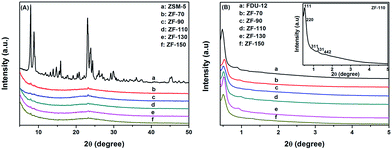
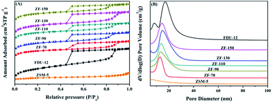
Wide angle (2θ = 5–50°) and low angle (2θ = 0.4–5°) X-ray diffraction (XRD) data were measured on the Bruker D8 advance system with Cu Kα radiation at 40 kV and 50 mA, and scan speeds of 1° min−1 and 2.4° min−1.The physicochemical properties of materials and catalysts were acquired with the Micromeritics TriStar II 3020 porosimetry analyzer at 77 K. The samples were outgassed at 350 °C for 4 h in a vacuum environment before being adsorbed by N2. The specific surface areas and pore size distributions were calculated using the Brunauer–Emmett–Teller (BET) method and Barrett–Joyner–Halenda (BJH) method with an adsorption branch.
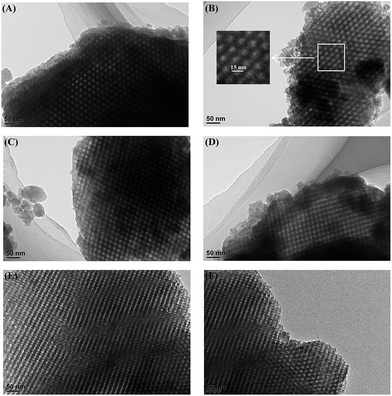
Transmission electron microscopy (TEM) images were taken on a JEOL JEM 2100 instrument with an accelerating voltage of 200 kV to obtain the channel structure of supports.
The morphologies of samples were obtained by emission scanning electron microscopy (SEM) on a Quanta 200F instrument under an acceleration voltage of 20 kV.
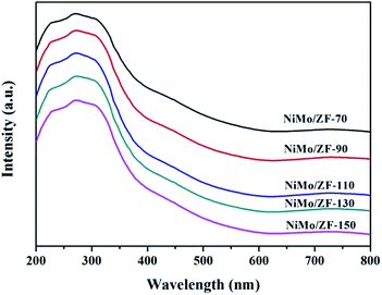
UV-Vis diffuse reflectance spectroscopy (UV-Vis DRS) results were collected using a Hitachi U-4100 device at the wavelength range from 200 nm to 800 nm with the integration sphere diffuse reflectance attachment.
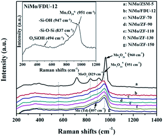
Raman spectra with wavenumbers of 1200–200 cm−1 were collected on a Renishaw Raman InVia Microscope (Spectra-Physics model 163) with a spectral resolution of 2 cm−1. A He/Cd laser line of 325 nm was employed as the excitation source with an output of 20 mW, and the laser spot size was approximately 1–2 μm with a power of 3.6 mW.
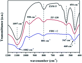
Fourier transform infrared (FTIR) absorbance spectra were recorded using a FTS-3000 spectrophotometer to obtain information on the acid strength and content of the catalysts. The catalysts were dehydrated at 500 °C for 5 h under vacuum before being adsorbed by purified pyridine vapor. B and L acid sites could be distinguished according to different outgassing temperatures, and the total acid content was calculated by IMEC(B) = 1.67 cm μmol−1 and IMEC(L) = 2.22 cm μmol−1.26
X-ray photoelectron spectroscopy (XPS) examination of the sulfurized catalysts was performed on a Perkin Elmer PHI-1600 ESCA spectrometer using Al Kα radiation (40 eV, <10–9 mbar). The sulfurized catalysts were left in a cyclohexane solution to prevent oxidation and pressed into a flake shape.
2.4 Catalytic activity
A 0.5 g amount of catalyst was loaded in the continuous flowing tubular fixed-bed inconel reactor (D = 9 mm, L = 50 mm) and presulfurized with a cyclohexane solution of 2.5 wt% CS2 at 340 °C, 4 MPa of H2 pressure and volume ratio of 200 for H2/oil for 4 h after being shaped into solid particles of 40–60 mesh. Then, the HDS performance of DBT of all catalysts was estimated employing DBT dissolved in cyclohexane as reaction raw feed (500 ppm S) under the same reaction conditions as that of presulfurization except for modulation of the various WHSV values of 20–150 h−1. The S content of the products was detected by a sulfur and nitrogen analyzer (RPP-2000SN, Taizhou Central Analytical Instruments Company, China), and the desulfurization rate was calculated by the following equation:| HDS efficiency = (Sf − Sp)/Sf × 100%. |
3. Results and discussion
3.1 Characterization of materials and catalysts
| Samples | SBETa (m2 g−1) | Vtb (cm3 g−1) | Vmesc (cm3 g−1) | Vmicd (cm3 g−1) | dBJHe (nm) |
|---|---|---|---|---|---|
| a Calculated by BET method.b The total pore volume was obtained at a relative pressure of 0.99.c Calculated using BJH method.d Calculated using the t-plot method.e Mesopore diameter was calculated using BJH method. | |||||
| ZSM-5 | 304 | 0.21 | 0.18 | 0.09 | |
| FDU-12 | 789 | 0.79 | 0.76 | 0.02 | 17.3 |
| ZF-70 | 564 | 0.47 | 0.40 | 0.04 | 12.4 |
| ZF-90 | 697 | 0.55 | 0.44 | 0.05 | 13.4 |
| ZF-110 | 648 | 0.51 | 0.39 | 0.05 | 14.0 |
| ZF-130 | 760 | 0.63 | 0.58 | 0.04 | 15.3 |
| ZF-150 | 733 | 0.54 | 0.39 | 0.06 | 15.4 |
| NiMo/ZSM-5 | 169 | 0.12 | 0.11 | 0.04 | — |
| NiMo/FDU-12 | 391 | 0.59 | 0.57 | 0.01 | 17.0 |
| NiMo/ZF-70 | 259 | 0.31 | 0.28 | 0.04 | 11.0 |
| NiMo/ZF-90 | 283 | 0.35 | 0.29 | 0.02 | 11.7 |
| NiMo/ZF-110 | 317 | 0.35 | 0.34 | 0.03 | 12.5 |
| NiMo/ZF-130 | 352 | 0.46 | 0.45 | 0.02 | 14.9 |
| NiMo/ZF-150 | 298 | 0.37 | 0.36 | 0.03 | 13.8 |
Fig. 6 displays the pyridine IR spectra of catalysts on absorbing pyridine after desorbing at 200 °C and 300 °C. As shown in Fig. 6(A), all NiMo/ZF-x catalysts showed a similar band at 1545 cm−1 as NiMo/ZSM-5, which was attributed to the B acid sites. However, there was no B acid located in NiMo/FDU-12 according to the absence of a characteristic signal at 1545 cm−1.38 The bands appearing at 1449 cm−1 and 1608 cm−1 were ascribed to the interactions of pyridine with L acid sites, while slight shifts were observed in NiMo/ZSM-5.39 Moreover, NiMo/ZSM-5 exhibited partially overlapped bands (at about 1630 cm−1) of B and L acid sites. In addition, the typical band present at 1489 cm−1 was also due to the combination of B and L acid sites.38,39
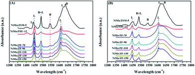 | ||
| Fig. 6 FTIR spectra of various catalysts on absorbing pyridine after degassing at (A) 200 °C and (B) 350 °C. | ||
Table 2 lists the distribution data of acid sites in the various catalysts. After desorbing pyridine at 200 °C, NiMo/ZSM-5 had the highest B acid content, while a few of the B acid sites were attached on the composite catalysts of NiMo/ZF-x due to the introduction of Al species. Furthermore, not only the total amount of acids, but also more L acids were generated in NiMo/ZF-x rather than in NiMo/FDU-12 at 200 °C and 300 °C. The total amount of B acid sites followed the order NiMo/ZSM-5 > NiMo/ZF-70 > NiMo/ZF-90 > NiMo/ZF-110 > NiMo/ZF-130 > NiMo/ZF-150. Wu19 demonstrated that moderate B acid sites facilitated the breakage of the C–S bond and finally accelerated the HDS reaction. Nevertheless, the medium and strong B acid sites did not exist in the series of NiMo/ZF-x catalysts as those obtained at 350 °C.
| Catalysts | Amount of acid sites (μmol g−1) | |||||
|---|---|---|---|---|---|---|
| 200 °C | 350 °C | |||||
| B | L | L + B | B | L | L + B | |
| NiMo/ZSM-5 | 53.4 | 61.0 | 114.4 | 26.4 | 29.8 | 56.2 |
| NiMo/FDU-12 | — | 60.5 | 60.5 | — | 25.2 | 25.2 |
| NiMo/ZF-70 | 11.7 | 96.1 | 107.8 | — | 42.6 | 42.6 |
| NiMo/ZF-90 | 9.0 | 82.2 | 91.2 | — | 35.7 | 35.7 |
| NiMo/ZF-110 | 8.8 | 75.6 | 84.4 | — | 31.3 | 31.3 |
| NiMo/ZF-130 | 7.5 | 78.4 | 85.9 | — | 33.8 | 33.8 |
| NiMo/ZF-150 | 6.4 | 65.8 | 72.2 | — | 30.4 | 30.4 |
![[double bond, length as m-dash]](https://www.rsc.org/images/entities/char_e001.gif) O located in the extreme of Mo7O246−.44–46 However, the single typical peak at 951 cm−1 could be distinctly observed in all NiMo supported aluminosilicate catalysts in Fig. 8, indicating that the hydroxyl groups of composite materials might be decorated to be Si–O–Al linked phases due to the incorporation of Al into the framework (FT-IR results in Fig. 2). Simultaneously, the wide characteristic peaks at 951 cm−1 confirmed the presence of a favorable dispersion of Mo7O246− on the NiMo/FDU-12 and NiMo/ZF-x catalysts. In general, it was easier to sulfurize Mo7O246− species due to their relatively weak interactions with supports, which appreciably favored the improvement of the degree of sulfurization of Mo species.47,48 The peak at 829 cm−1 was attributed to Mo–O–Mo in the orthorhombic MoO3. The slightly aggregated MoO3 on the surface of NiMo/ZF-x (x = 70, 90) should be caused by the introduction of redundant Al species. And NiMo/ZSM-5 has higher content of Al species, so it shows a relatively stronger characteristic peak of aggregated MoO3.49 Moreover, only NiMo/ZSM-5 displayed a Raman signal at 960 cm−1, which was associated with the vibrational mode of Mo8O264−, supporting the intensive chemical effects between Mo species and microporous ZSM-5 zeolite.50 The typical peak situated at 897 cm−1 was clearly observed in NiMo/ZF-150, but absent in NiMo/ZF-130, was ascribed to the interaction of tetrahedral Mo species, which was inactive for HDS.47,51 Overall, the characteristic Raman spectra of NiMo/ZF-130 were distinct from those of NiMo/ZSM-5 and NiMo/FDU-12. Moreover, it can be deduced that NiMo/ZF-130, with the higher ratio of Mo7O246− species, might possess extraordinary HDS efficiency.
O located in the extreme of Mo7O246−.44–46 However, the single typical peak at 951 cm−1 could be distinctly observed in all NiMo supported aluminosilicate catalysts in Fig. 8, indicating that the hydroxyl groups of composite materials might be decorated to be Si–O–Al linked phases due to the incorporation of Al into the framework (FT-IR results in Fig. 2). Simultaneously, the wide characteristic peaks at 951 cm−1 confirmed the presence of a favorable dispersion of Mo7O246− on the NiMo/FDU-12 and NiMo/ZF-x catalysts. In general, it was easier to sulfurize Mo7O246− species due to their relatively weak interactions with supports, which appreciably favored the improvement of the degree of sulfurization of Mo species.47,48 The peak at 829 cm−1 was attributed to Mo–O–Mo in the orthorhombic MoO3. The slightly aggregated MoO3 on the surface of NiMo/ZF-x (x = 70, 90) should be caused by the introduction of redundant Al species. And NiMo/ZSM-5 has higher content of Al species, so it shows a relatively stronger characteristic peak of aggregated MoO3.49 Moreover, only NiMo/ZSM-5 displayed a Raman signal at 960 cm−1, which was associated with the vibrational mode of Mo8O264−, supporting the intensive chemical effects between Mo species and microporous ZSM-5 zeolite.50 The typical peak situated at 897 cm−1 was clearly observed in NiMo/ZF-150, but absent in NiMo/ZF-130, was ascribed to the interaction of tetrahedral Mo species, which was inactive for HDS.47,51 Overall, the characteristic Raman spectra of NiMo/ZF-130 were distinct from those of NiMo/ZSM-5 and NiMo/FDU-12. Moreover, it can be deduced that NiMo/ZF-130, with the higher ratio of Mo7O246− species, might possess extraordinary HDS efficiency.
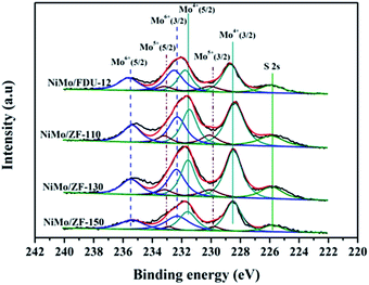 | ||
| Fig. 9 Mo 3d XPS spectra of the sulfurized catalysts NiMo/FDU-12 and NiMo/ZF-x with different SiO2/Al2O3 ratios. | ||
| Catalysts | Mo4+ | Mo5+ | Mo6+ | SMb | |||
|---|---|---|---|---|---|---|---|
| ara% (228.6 eV) | ar% (231.6 eV) | ar% (229.9 eV) | ar% (233.1 eV) | ar% (232.3 eV) | ar% (235.5 eV) | ||
| a ar% means the area percent of the XPS peak.b SM = Mosulfurization = Mo4+/(Mo4+ + Mo5+ + Mo6+). | |||||||
| NiMo/FDU-12 | 29 | 19 | 9 | 4 | 24 | 15 | 48 |
| NiMo/ZF-110 | 33 | 22 | 6 | 5 | 20 | 14 | 55 |
| NiMo/ZF-130 | 35 | 23 | 6 | 4 | 20 | 12 | 58 |
| NiMo/ZF-150 | 33 | 21 | 5 | 3 | 23 | 15 | 54 |
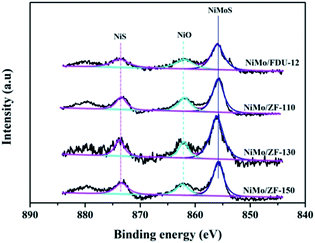
For the sulfurized catalysts, the Ni 2p XPS spectral curves were caused by the NiS, NiO and NiMoS species.53 Moreover, the Ni 2p XPS spectra of the catalysts NiMo/FDU-12 and NiMo/ZF-x are shown in Fig. 10. All Ni 2p envelopes disintegrated into three fitted curves located at BE 873.6 ± 0.1 eV, 862.2 ± 0.1 eV and 855.8 ± 0.1 eV, which could be ascribed to NiS (2p1/2), NiO and NiMoS phases, respectively.54,55 In addition, the detailed information of various Ni species is summarized in Table 4. The ratio of NiMoS/Nitotal followed the order NiMo/ZF-130 > NiMo/ZF-150 > NiMo/ZF-110 > NiMo/FDU-12. Compared to NiO and NiS, NiMoS phases were preferable and more capable of driving the HDS reaction. The lowest ratio of NiMoS/Nitotal, but the largest value of NiO and NiS, could be obtained in the NiMo/FDU-12 catalyst due to the lack of ZSM-5 structural units according to the FT-IR analysis. And the highest ratio of NiMoS/Nitotal observed in the NiMo/ZF-130, which corresponds well to its excellent physicochemical properties, can achieve to 64%.
3.2 Catalytic performance of the catalysts
It is extremely important to remove the heterocyclic sulfur compound DBT contained in diesel in order to produce ultra clean fuel. Hence, DBT served as the probe molecule and was used in evaluating the HDS efficiencies of catalysts over different carriers of FDU-12 and ZF-x. All catalysts exhibited higher HDS efficiencies than the pure mesoporous catalyst NiMo/FDU-12 as shown in Fig. 11. The approximate trend was NiMo/ZF-130 > NiMo/ZF-110 > NiMo/ZF-150 > NiMo/ZF-90 > NiMo/ZF-70 > NiMo/FDU-12, and the HDS efficiencies of all catalysts gradually decreased with an increase in WHSV, which was detrimental to the reaction time. The catalyst NiMo/ZF-130 displayed a higher specific surface area and lager pore sizes. The former high specific surface area was achieved by a suitable dispersion of Mo species. The larger pore sizes decreased the diffusion resistance of DBT. Moreover, the highest HDS ratio was observed in the NiMo/ZF-130 with a WHSV range from 20 h−1 to 120 h−1 rather than in the other composite catalysts of NiMo/ZF-x. The catalyst NiMo/ZF-130 showed higher HDS efficiencies than NiMo/C-MA in the range of 20 h−1 to 100 h−1 due to their differences in physical and chemical properties. The absence of B acid sites in the catalyst NiMo/C-MA made it difficult to break the C–S bond in the heterocyclic sulphides, and the narrower pore channels increased the diffusion resistance of the larger-sized reactants; hence, NiMo/C-MA could not achieve the desired HDS performance.56 The catalyst NiMo/FDU-12 possessed the largest superficial area and pore volume, which could afford an excellent platform for the dispersion of active metal species and eliminate the mass transfer resistance of DBT, respectively. However, the catalyst NiMo/FDU-12 displayed the lowest performance for the HDS reaction.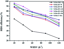 | ||
| Fig. 11 DBT HDS efficiency over the catalysts NiMo/FDU-12, NiMo/ZF-x and NiMo/C-MA (commercial mesoporous γ-Al2O3) at various WHSV values. | ||
Actually, not only physical properties, but also the acidity (B + L) and the Al species in the catalysts had synergetic effects on the HDS reaction. The L acid sites favored the hydrogenation of DBT on the surface of the catalysts. Moreover, the B acid sites accelerated the breakage of the C–S bond in the DBT, which determined the rates of HDS in both DDS (direct desulphurization) and HYD (hydrogenation) reaction processes. As for the absence of B acid sites, it is resonable that catalyst NiMo/FDU-12 has the lowest removal rate of DBT under the uniform reaction conditions. However, the excessive B acid sites were inclined to induce carbon depositions in the catalysts, which covered the active metal sites and prevented them from making contact with DBT. As a result, the catalyst NiMo/ZF-70 showed a lower HDS efficiency of DBT at 20 h−1, ∼87.8%. The catalyst NiMo/ZF-130 exhibited the appropriate content of B and L acid sites. The Al species were incorporated into the frameworks and fixed on the surface of the composite catalysts NiMo/ZF-x. As an electronic accelerator, the Al species could adjust the interactions between the active metal components and the supports, and facilitate the dispersion of metal species over the catalysts. Nevertheless, the excessive Al species led to the shrinkage of the pores, which was unfavorable for the metal dispersion and the utilization of Mo species to a certain extent. The NiMo supported catalyst with a SiO2/Al2O3 of 130 possessed a suitable Al content, which optimized the interactions between the NiMo species and the supports. Therefore, the catalyst NiMo/ZF-130 exhibited the lager content of Mo7O246− which was easier to sulfurize. Also, NiMo/ZF-130 had the highest ratios of Mo4+/Mototal and NiMoS/Nitotal, which was in agreement with the results of the XPS spectra. Sufficient active sites in MoS2 could effectively accomplish the thorough removal of sulfides.
In summary, NiMo/ZF-130 was more capable of eliminating DBT than other catalysts under the same reaction conditions, and the HDS efficiency approached 96.3% at 20 h−1.
4. Conclusions
The hierarchical, porous composites of ZF-x with various ratios of SiO2/Al2O3 were successfully synthesized according to an in situ, nano-assembly method using ZSM-5 microporous crystals as the source of silica. Wide-angle XRD spectra confirmed that a MFI topological structure was present in the ZF-x samples. Especially, the analysis of FTIR showed the typical vibration of five-membered rings of T–O–T (T = Al or Si), and the pyridine IR results supported the existence of certain B acid sites. Moreover, solid particles of ZSM-5 crystallographic seeds were not observed in the SEM images, illustrating that ZSM-5 structural units were chemically incorporated into the framework of carriers of ZF-x rather than in the mechanical mixing. Moreover, nitrogen physisorption analysis showed that micro-mesoporous materials of ZF-x not only had a Fm3m structure similar to that of the pure mesoporous silica FDU-12, but the corresponding catalysts and symmetrical crystal lattices with a long-range still remained in the ZF-130 composite, as shown in the TEM images. The Raman spectral peaks showed that there was no agglomerated MoO3 clusters on the surface of NiMo/FDU-12 and NiMo/ZF-130. It was noted that the sulfurized, composite catalysts NiMo/ZF-x exhibited higher sulfurization than NiMo/FDU-12, and the catalyst NiMo/ZF-130 had the highest ratio of Mo4+/Mototal and NiMoS/Nitotal as shown in the XPS spectra. The specific HDS efficiency followed the order NiMo/ZF-130 > NiMo/ZF-110 > NiMo/ZF-150 > NiMo/ZF-90 > NiMo/ZF-70 > NiMo/FDU-12. Apparently, the catalyst NiMo/ZF-130 exhibited the highest efficiency (96.3%) of DBT HDS at 20 h−1 due to its superior physicochemical properties. The larger specific surface area and pore sizes of the catalyst NiMo/ZF-130 could promote the good dispersion of Mo species on the surface of supports and decrease the diffusion resistance of DBT reactants inside the channels, respectively. In addition, the moderate B acid sites, the largest MoS2 and NiMoS active phases could accelerate the HDS reaction. Most importantly, the composites of ZF-x actually combined the advantages of microporous zeolites and mesoporous materials, and the corresponding catalysts played a significant role in the desulfurization of fuel oil.Acknowledgements
This study was financially supported by the CNOOC project (CNOOC-KJ 135 FZDXM 00 LH 003 LH-2016), the National Natural Science Foundation of China (No. 21676298, U1463207 and 21503152), the Opening Project of Guangxi Key Laboratory of Petrochemical Resource Processing and the Process Intensification Technology (2015K003), CNPC Key Research Project and KLGCP (GCP201401).Notes and references
- S. Velu, S. Watanabe, X. Ma and C. S. Song, Appl. Catal., B, 2003, 41, 207–238 CrossRef.
- F. Trejo, M. S. Rana and J. Ancheyta, Catal. Today, 2008, 2, 327–336 CrossRef.
- Y. Shen, T. Sun and J. Jia, RSC Adv., 2012, 2, 3123–3132 RSC.
- J. Hu, Z. Zhang and F. Wang, RSC Adv., 2016, 6, 101544–101551 RSC.
- S. Saravanamurugan, M. Paniagua, J. A. Melero and A. Riisager, J. Am. Chem. Soc., 2013, 135, 5246–5249 CrossRef CAS PubMed.
- W. Wu and E. Weitz, Appl. Surf. Sci., 2014, 1, 405–415 CrossRef.
- H. P. Winoto, B. S. Ahn and J. Jae, J. Ind. Eng. Chem., 2016, 40, 62–71 CrossRef CAS.
- L. Y. Han, Y. Luo, J. Liu and Z. Zhao, Ind. Catal., 2011, 11, 46–50 Search PubMed.
- J. Liu, L. H. Yu, Z. Zhao, Y. S. Chen, P. Y. Zhu, C. Yan and Y. Luo, J. Catal., 2012, 1, 134–144 CrossRef.
- R. Huirache-Acuña, B. Pawelec, C. V. Loricera, E. M. Rivera-Muñoz, R. Nava, B. Torres and J. L. G. Fierro, Appl. Catal., B, 2012, 125, 473–485 CrossRef.
- Z. K. Cao, A. J. Duan, Z. Zhao, J. M. Li, Y. C. Wei, G. Y. Jiang and J. Liu, J. Mater. Chem. A, 2014, 46, 19738–19749 Search PubMed.
- D. W. Gao, A. J. Duan, X. Zhang, K. B. Chi and Z. Zhao, J. Mater. Chem. A, 2015, 32, 16501–16512 Search PubMed.
- D. W. Gao, A. M. Zheng, X. Zhang, H. Sun, X. P. Dai and A. J. Duan, Nanoscale, 2015, 25, 10918–10924 RSC.
- D. Q. Zhang, A. J. Duan, Z. Zhao and C. M. Xu, J. Catal., 2010, 2, 273–286 CrossRef.
- Q. Tang, H. Xu, Y. Y. Zheng, J. F. Wang, H. S. Li and J. Zhang, Appl. Catal., A, 2012, 1, 36–42 CrossRef.
- H. S. Li, S. C. He, Q. Z. Jiao and K. N. Sun, Appl. Catal., A, 2013, 2, 152–159 CrossRef.
- R. Barakov, N. Shcherban and P. Yaremov, J. Mater. Sci., 2016, 8, 4002–4020 CrossRef.
- Y. Fang and H. Hu, J. Am. Chem. Soc., 2006, 33, 10636–10637 CrossRef PubMed.
- H. D. Wu, A. J. Duan, Z. Zhao, T. S. Li, P. Roel and X. F. Zhou, J. Catal., 2014, 317, 303–317 CrossRef CAS.
- G. Busca, Chem. Rev., 2007, 107, 5366–5410 CrossRef CAS PubMed.
- R. Weingarten, G. A. Tompsett, W. C. Conner and G. W. Huber, J. Catal., 2011, 279, 174–182 CrossRef CAS.
- J. Fan, C. Z. Yu, F. Gao, J. Lei, B. Z. Tian, L. M. Wang, Q. Luo, B. Tu, W. Z. Zhou and D. Y. Zhao, Angew. Chem., Int. Ed., 2003, 27, 3254–3258 CrossRef.
- O. Ersen, J. Parmentier, L. A. Solovyov, M. Drillon and C. Pham-Huu, J. Am. Chem. Soc., 2009, 49, 16800–16806 Search PubMed.
- P. Du, P. Zheng, S. T. Song, M. H. Zhang and A. J. Duan, RSC Adv., 2015, 2, 1018–1026 Search PubMed.
- H. Li, F. Zhang, H. Yin, Y. Wan and Y. Lu, Green Chem., 2007, 5, 500–505 RSC.
- C. A. Emeis, ChemInform, 1993, 38, 347–354 Search PubMed.
- C. He, J. J. Li, P. Li, J. Cheng, Z. P. Hao and Z. P. Xu, Appl. Catal., B, 2010, 3–4, 466–475 CrossRef.
- J. L. Jiang, Y. Yang, C. Duan, Y. Xu, L. D. Feng, Xu. Gu and J. Chen, Microporous Mesoporous Mater., 2012, 30, 11–20 CrossRef.
- G. Liu, F. X. Li, W. Wei, S. Liu and W. Jin, Chem. Eng. J., 2011, 2, 495–503 CrossRef.
- Y. L. Su, J. Wang and H. Liu, Langmuir, 2002, 3, 865–871 CrossRef.
- Y. L. Su, X. F. Wei and H. Z. Liu, J. Colloid Interface Sci., 2003, 2, 526–531 CrossRef.
- M. Almgren, P. Bahadur and M. Jansson, J. Colloid Interface Sci., 1992, 1, 157–165 CrossRef.
- K. Michal, J. Mietek, K. A. Taewan and R. Ryoo, Chem. Mater., 2003, 14, 2815–2823 Search PubMed.
- J. C. P. Broekhoff and J. H. D. Boer, J. Catal., 1968, 4, 377–390 CrossRef.
- J. Fan, C. Z. Yu and J. Lei, J. Am. Chem. Soc., 2005, 31, 10794–10795 CrossRef PubMed.
- J. Tang, J. Liu, P. Wang, H. Zhong and Q. Yang, Microporous Mesoporous Mater., 2010, 1, 119–125 CrossRef.
- F. Zaera, ChemInform, 2015, 3, 7624–7663 Search PubMed.
- J. A. Z. Pieterse, S. Veefkind-Reyes, K. Seshan, L. Domokos and J. A. Lercher, J. Catal., 1999, 2, 518–520 CrossRef.
- T. Kataoka and J. A. Dumesic, ChemInform, 1988, 42, 66–79 Search PubMed.
- T. Klimova, L. Pena, L. Lizama, C. Salcedo and O. Y. Gutiérrez, Ind. Eng. Chem. Res., 2008, 48, 1126–1133 CrossRef.
- G. Xiong, Z. Feng and J. Li, J. Phys. Chem. B, 2000, 104, 3581–3588 CrossRef CAS.
- B. Riegel, I. Hartmann and W. Kiefer, J. Non-Cryst. Solids, 1997, 3, 294–298 CrossRef.
- Y. Borodko, J. W. Ager and G. E. Marti, J. Phys. Chem. B, 2005, 37, 17386–17390 CrossRef PubMed.
- S. Chytil, L. Haugland and E. A. Blekkan, Microporous Mesoporous Mater., 2008, 1–3, 134–142 CrossRef.
- C. Hess, G. Tzolova-Müller and R. Herbert, J. Phys. Chem. C, 2007, 26, 9471–9479 Search PubMed.
- E. Payen, J. Grimblot and S. Kasztelan, ChemInform, 1988, 14, 6642–6648 Search PubMed.
- D. S. Kim, I. E. Wachs and K. Segawa, J. Catal., 1994, 2, 268–277 CrossRef.
- M. A. Vuurman and I. E. Wachs, J. Phys. Chem., 2002, 12, 5008–5016 Search PubMed.
- T. E. Klimova, D. Valencia, J. A. Mendoza-Nieto and P. Hernández-Hipólito, J. Catal., 2013, 11, 29–46 CrossRef.
- K. H. Choi, Y. Korai and I. Mochida, Appl. Catal., A, 2004, 2, 229–236 CrossRef.
- M. Adachi, C. Contescu and J. A. Schwarz, J. Catal., 1996, 1, 66–75 CrossRef.
- X. L. Wang, H. Fang and Z. Zhao, RSC Adv., 2015, 5, 99706–99711 RSC.
- W. K. Lai, W. J. Song and L. Q. Pang, J. Catal., 2013, 13, 80–91 CrossRef.
- S. Jiang, Y. Zhou and S. Ding, RSC Adv., 2016, 6, 106680–106689 RSC.
- B. Guichard, M. Roy-Auberger and E. Devers, Catal. Today, 2008, 1, 97–108 CrossRef.
- X. L. Wang, Z. Zhao and P. Zheng, J. Catal., 2016, 344, 680–691 CrossRef CAS.
Footnotes |
| † Electronic supplementary information (ESI) available. See DOI: 10.1039/c7ra03679e |
| ‡ This author has equal contribution as the first author. |
| This journal is © The Royal Society of Chemistry 2017 |

